Mitsubishi Electric 800 Series Instruction Manual
575v class, compact, high functionality inverters, 0.75k-7.5k
Hide thumbs
Also See for 800 Series:
- Instruction manual (727 pages) ,
- Instruction manual (function (534 pages) ,
- Manual (183 pages)

Related Manuals for Mitsubishi Electric 800 Series


Summary of Contents for Mitsubishi Electric 800 Series
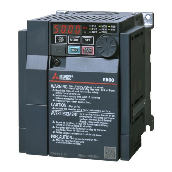
- Page 1 INVERTER FR-E860 Instruction Manual (Connection) (575V CLASS) Compact, high functionality inverters FR-E860-0017(0.75K) to 0120(7.5K) FR-E860-0017(0.75K) to 0120(7.5K)E FR-E860-0017(0.75K) to 0120(7.5K)SCE...
-
Page 2: Table Of Contents
Safety Instructions ..............3 Chapter 1 Introduction . - Page 3 2.8.2 Connection of the DC reactor ............... 65 Chapter 3 Precautions for Use of the Inverter.
-
Page 4: Safety Instructions
• A person who possesses a certification in regard with electric appliance handling, or person took a proper engineering training. Such training may be available at your local Mitsubishi Electric office. Contact your local sales office for schedules and locations. - Page 5 Electric shock prevention WARNING Do not remove the front cover or the wiring cover while the power of this product is ON, and do not run this product with the front cover or the wiring cover removed as the exposed high voltage terminals or the charging part of the circuitry can be touched.
- Page 6 Additional instructions The following instructions must be also followed. If the product is handled incorrectly, it may cause unexpected fault, an injury, or an electric shock. CAUTION Transportation and installation To prevent injury, wear cut-resistant gloves when opening packaging with sharp tools. ...
- Page 7 WARNING Usage Stay away from the equipment after using the retry function in this product as the equipment will restart suddenly after the output shutoff of this product. Access to the motor is allowed only after it is fully confirmed that the motor does not start running. ...
- Page 8 CAUTION Usage When installing the MC on the output side of the inverter, turn it ON/OFF while both the inverter and motor are at a stop. The electronic thermal O/L relay function may not be enough for protection of a motor from overheating. It is recommended to install an external thermal relay for overheat protection.
- Page 9 Compliance with the EU Machinery Directive—Safety functions To achieve functional safety, any work on the product such as wiring and inspections must be performed according to this document and the FR-E800-SCE Instruction Manual (Functional Safety) by technicians who took a safety standard training. WARNING ...
- Page 10 CHAPTER 1 Introduction Product checking and accessories .........................11 Component names ..............................13 Operation steps ..............................17 Related manuals..............................19...
-
Page 11: Chapter 1 Introduction
Abbreviations Item Description Parameter unit LCD operation panel (FR-LU08) and enclosure surface operation panel (FR-PA07) Inverter Mitsubishi Electric inverter FR-E800 series E800 Standard model (RS485 + SIL2/PLd functional safety) E800-E Ethernet model (Ethernet + SIL2/PLd functional safety) E800-SCE Safety communication model (Ethernet + SIL3/PLe functional safety) -
Page 12: Product Checking And Accessories
Product checking and accessories Unpack the product and check the rating plate and the capacity plate of the inverter to ensure that the model agrees with the order and the product is intact. Inverter model Rating plate Inverter model MODEL :FR-E860-0017-1 Input rating INPUT :XXXXX... - Page 13 • E: Availability of circuit board coating / plated conductors is shown. Symbol Circuit board coating Plated conductor None Without coating Without plated conductors With coating Without plated conductors Conforming to IEC 60721-3-3 3C2 NOTE • In this Instruction Manual, the inverter model name consists of the inverter rated current and the applicable motor capacity. (Example) FR-E860-0017(0.75K) ...
-
Page 14: Component Names
Component names Standard model Component names are as follows. 1. Introduction 1.2 Component names... - Page 15 Refer to Symbol Name Description page Instruction Plug-in option connection connector Connects a plug-in option or a communication option. Manual of the option Control logic switch Select the sink logic (SINK) or the source logic (SOURCE). Voltage/current input switch Select voltage or current for the input via terminals 2 and 4. PU connector Used for the RS-485 communication.
- Page 16 Ethernet model Component names are as follows. Refer to Symbol Name Description page Instruction Plug-in option connection connector Connector for a plug-in option or a communication option. Manual of the option Control logic switch Select the sink logic (SINK) or the source logic (SOURCE). Voltage/current input switch Select voltage or current for the input via terminals 2 and 4.
- Page 17 Safety communication model Component names are as follows. Refer to Symbol Name Description page Instruction Plug-in option connection connector Connects a plug-in option or a communication option. Manual of the option Voltage/current input switch Select voltage or current for the input via terminals 2 and 4. Ethernet connector (2 ports) Connector for the Ethernet dedicated cable for connection to the network.
-
Page 18: Operation Steps
Operation steps : Initial setting Step of operation Frequency command Installation/mounting Inverter output Wiring of the power frequency supply and motor Time (Hz) Start command Control mode selection Start command via the PU/Ethernet connector of the inverter and plug-in to give a start to give a start to give a start option (Communication) - Page 19 Symbol Overview Refer to page Install the inverter. Perform wiring for the power supply and the motor. Select the control method (V/F control, Advanced magnetic flux vector control, Real sensorless vector control, Instruction Manual and PM sensorless vector control). (Function) Instruction Manual Give the start command via communication.
-
Page 20: Related Manuals
Related manuals The manuals related to FR-E800 are as follows. Manual name Manual number FR-E860 Inverter Safety Guideline IB-0600862ENG FR-E860-E Inverter Safety Guideline IB-0600863ENG FR-E860-SCE Inverter Safety Guideline IB-0600924ENG FR-E800 Instruction Manual (Function) IB-0600868ENG FR-E800 Instruction Manual (Communication) IB-0600871ENG FR-E800 Instruction Manual (Maintenance) IB-0600874ENG FR-E800 Instruction Manual (Functional Safety) BCN-A23488-000... - Page 21 MEMO 1. Introduction 1.4 Related manuals...
- Page 22 CHAPTER 2 Installation and Wiring Peripheral devices ..............................22 Removal and reinstallation of the front cover ......................25 Installation of the inverter and enclosure design ....................27 Terminal connection diagrams..........................33 Main circuit terminals ..............................39 Control circuit................................44 Communication connectors and terminals......................61 Connection of stand-alone option units ........................64...
-
Page 23: Chapter 2 Installation And Wiring
Installation and Wiring This chapter explains the installation and the wiring of this product. Always read the instructions before use. Peripheral devices 2.1.1 Inverter and peripheral devices (b) Three-phase AC power supply (c) Molded case circuit breaker (h) USB power supply (MCCB) or earth leakage USB device current breaker (ELB), fuse... - Page 24 Refer to Symbol Name Overview page The life of the inverter is influenced by the surrounding air temperature. The surrounding air temperature should be as low as possible within the permissible range. This must be noted especially when the inverter is Inverter (FR-E800) installed in an enclosure.
-
Page 25: Peripheral Devices
2.1.2 Peripheral devices Check the model of the inverter you purchased. Appropriate peripheral devices must be selected according to the capacity. Refer to the following table for right selection. Molded case circuit breaker / earth leakage circuit breaker • The following shows the rated current of the molded case circuit breaker (MCCB) or earth leakage circuit breaker (ELB). Without AC/DC power factor With AC/DC power factor improving improving reactor... -
Page 26: Removal And Reinstallation Of The
Removal and reinstallation of the front cover Removal of the front cover • Example of the FR-E860-0017(0.75K) Loosen Loosen Loosen Loosen the screw on the front cover. (This screw cannot be removed.) Pull out the cover using its lower side as a support. With the cover removed, the control circuit terminals can be wired and the plug-in option can be installed. - Page 27 NOTE • Fully make sure that the front cover has been reinstalled securely. Always tighten the installation screws of the front cover. Removal of the wiring cover • FR-E860-0040(2.2K) or lower Guides Guides Guides Screwdriver Screwdriver Screwdriver Insert a tool such as a flathead screwdriver into the half-hole above the "PUSH" mark on the wiring cover to push the stopper behind the wiring cover approx.
-
Page 28: Installation Of The Inverter And Enclosure Design
Installation of the inverter and enclosure design 2.3.1 Inverter installation environment The following table lists the standard specifications of the inverter installation environment. Using the inverter in an environment that does not satisfy the conditions deteriorates the performance, shortens the life, and causes a failure. Refer to the following points, and take adequate measures. - Page 29 Humidity Operate the inverter within the ambient air humidity of usually 45 to 90% (up to 95% with circuit board coating). Too high humidity will pose problems of reduced insulation and metal corrosion. On the other hand, too low humidity may cause a spatial electrical breakdown.
-
Page 30: Amount Of Heat Generated By The Inverter
Countermeasure • Provide the enclosure with rubber vibration isolators. • Strengthen the structure to prevent the enclosure from resonance. • Install the enclosure away from the sources of the vibration. 2.3.2 Amount of heat generated by the inverter Installing the heat sink inside the enclosure When the heat sink is installed inside the enclosure, the amount of heat generated by the inverter unit is shown in the following tables. -
Page 31: Inverter Installation
• Cooling by heat exchanger or cooler (heat pipe, cooler, etc.) Cooling system Enclosure structure Comment This system is low in cost and generally used, but the Natural ventilation (enclosed enclosure size increases as the inverter capacity type / open type) increases. - Page 32 • When designing or building an enclosure for the inverter, carefully consider influencing factors such as heat generation of the contained devices and the operating environment. Clearances (front) Clearances (side) 10 cm or more 1 cm 1 cm 1 cm or more or more Allow clearance.
- Page 33 Arrangement of the ventilation fan and inverter Heat generated in the inverter is blown up from the bottom of the unit as warm air by the cooling fan. When installing a ventilation fan for that heat, determine the place of ventilation fan installation after fully considering an air flow. (Air passes through areas of low resistance.
-
Page 34: Terminal Connection Diagrams
Terminal connection diagrams Standard model Sink logic Main circuit terminal Control circuit terminal DC reactor Earth (Ground) Jumper PR N/- MCCB Motor R/L1 Three-phase S/L2 AC power T/L3 supply Earth (Ground) Earth Main circuit (Ground) Control circuit Relay output Control input signals (No voltage input allowed) Forward rotation start... - Page 35 The initial setting varies depending on the specification. Terminal input specifications can be changed by analog input specification switchover (Pr.73, Pr.267). To input voltage, set the voltage/current input selection switch to "V". To input current, set the switch to "I". The initial setting varies depending on the specification. (Refer to the FR-E800 Instruction Manual (Function).) It is recommended to use 2 W 1 kΩ...
- Page 36 Ethernet model Sink logic Main circuit terminal Control circuit terminal DC reactor Earth (Ground) PR N/- Jumper MCCB Motor R/L1 Three-phase S/L2 AC power T/L3 supply Earth (Ground) Earth Main circuit (Ground) Control circuit Relay output Control input signals (No voltage input allowed) Forward rotation start Relay output...
- Page 37 NOTE • To prevent a malfunction due to noise, keep the signal cables 10 cm or more away from the power cables. Also, keep the cables of the main circuit for input and output separated. • After wiring, wire offcuts must not be left in the inverter. Wire offcuts can cause a fault, failure or malfunction.
- Page 38 Safety communication model Source logic Main circuit terminal Control circuit terminal Brake unit DC reactor (Option) Earth (Ground) PR N/- Jumper MCCB Motor R/L1 Three-phase S/L2 AC power T/L3 supply Earth (Ground) Main circuit Earth (Ground) Control circuit Relay output Relay output (Fault output) Safety communication function selection...
- Page 39 NOTE • To prevent a malfunction due to noise, keep the signal cables 10 cm or more away from the power cables. Also, keep the cables of the main circuit for input and output separated. • After wiring, wire offcuts must not be left in the inverter. Wire offcuts can cause a fault, failure or malfunction.
-
Page 40: Main Circuit Terminals
Main circuit terminals 2.5.1 Details on the main circuit terminals Refer to Terminal symbol Terminal name Terminal function description page R/L1, S/L2, T/L3 AC power input Connect these terminals to the commercial power supply. — Connect these terminals to a three-phase squirrel cage motor or a PM U, V, W Inverter output —... -
Page 41: Applicable Cables And Wiring Length
2.5.3 Applicable cables and wiring length For the ND rating • 575 V class (575 V input power supply, without a power factor improving AC or DC reactor) Cable gauge Crimp HIV cables, terminal Terminal Tightening AWG/MCM Applicable inverter model etc. - Page 42 • 575 V class (575 V input power supply, with a power factor improving AC or DC reactor) Cable gauge Crimp HIV cables, terminal Terminal Tightening AWG/MCM Applicable inverter model etc. (mm screw torque FR-E860-[] size (N·m) R/L1, R/L1, R/L1, S/L2, U, V, W S/L2,...
- Page 43 With PM motor Use the wiring length of 100 m or shorter when connecting a PM motor. Use one PM motor for one inverter. Multiple PM motors cannot be connected to an inverter. When the wiring length exceeds 50 m for a 600 V class motor driven by an inverter under PM sensorless vector control, set "9" (6 kHz) or less in Pr.72 PWM frequency selection.
-
Page 44: Earthing (Grounding) Precautions
2.5.4 Earthing (grounding) precautions Always earth (ground) the motor and inverter. Purpose of earthing (grounding) Generally, an electrical apparatus has an earth (ground) terminal, which must be connected to the ground before use. An electrical circuit is usually insulated by an insulating material and encased. However, it is impossible to manufacture an insulating material that can shut off a leakage current completely, and actually, a slight current flows into the case. -
Page 45: Control Circuit
Control circuit 2.6.1 Details on the control circuit terminals (Standard model) Input signal Refer Terminal Type Terminal name Terminal function description Rated specification symbol page Turn ON the STF signal to start When the STF and Forward rotation start forward rotation and turn it OFF to STR signals are turned stop. - Page 46 Refer Terminal Type Terminal name Terminal function description Rated specification symbol page 5 ±0.5 VDC, Frequency setting Used as the power supply for an external frequency setting permissible load current: power supply (speed setting) potentiometer. 10 mA Inputting 0 to 5 VDC (or 0 to 10 VDC) provides the maximum output frequency at 5 V (or 10 V) and makes input and output proportional.
- Page 47 Safety stop signal Terminal Refer to Terminal name Terminal function description Rated specification symbol page Use terminals S1 and S2 to receive the safety stop signal input from the safety relay module. Terminals S1 and S2 can be used Input resistance: 4.7 kΩ, Safety stop input at a time (dual channel).
-
Page 48: Details On The Control Circuit Terminals (Ethernet Model)
2.6.2 Details on the control circuit terminals (Ethernet model) Input signal Refer Terminal Type Terminal name Terminal function description Rated specification symbol page Turn ON the STF signal to start Input resistance: 4.7 kΩ, When the STF and Forward rotation start forward rotation and turn it OFF to voltage when contacts STR signals are turned... - Page 49 Output signal Terminal Refer Type Terminal name Terminal function description Rated specification symbol to page 1 changeover contact output that indicates that an inverter's protective function has been activated and the outputs are Contact capacity: 240 Relay output (fault stopped.
-
Page 50: Details On The Control Circuit Terminals (Safety Communication Model)
2.6.3 Details on the control circuit terminals (Safety communication model) Input signal Refer Terminal Type Terminal name Terminal function description Rated specification symbol page 5 ±0.5 VDC, Frequency setting Used as the power supply for an external frequency setting permissible load current: power supply (speed setting) potentiometer. -
Page 51: Control Logic (Sink/Source) Change (Standard Model / Ethernet Model)
Safety input/output signal Termin Refer Type Terminal name Terminal function description Rated specification to page symbol 24 VDC power supply common Common output terminal for 24 VDC 0.1 A power supply — (terminal PC). Isolated from terminal 5. External transistor common (source) Power supply voltage Safety input terminal... - Page 52 (The output signals may be used in either the sink or source logic independently of the switch setting.) For sink logic SINK SOURCE NOTE • Never change the control logic while power is ON. Sink logic and source logic •...
-
Page 53: Wiring Of Control Circuit
• When using an external power supply for transistor output Sink logic Source logic Use terminal PC as a common terminal, and perform wiring as Use terminal SD as a common terminal, and perform wiring as follows. (Do not connect terminal SD on the inverter with the follows. - Page 54 Ethernet model • Recommended cable gauge: 0.3 to 0.75 mm S1 S2 PC D10 DI1 SD SO SOC Safety communication model • Recommended cable gauge: 0.3 to 0.75 mm SX1 SX2 PC SD Wiring method Power supply connection Use crimp terminals and stripped wire for the control circuit wiring.
- Page 55 Crimp the terminals on the wire. Insert wires to the crimp terminal, and check that the wires come out for about 0 to 0.5 mm from a sleeve. Check the condition of the crimp terminals after crimping. Do not use the crimp terminals of which the crimping is inappropriate, or the face is damaged.
- Page 56 Wire removal Pull the wire while pushing the open/close button all the way down firmly with a flathead screwdriver. Open/close button Flathead screwdriver NOTE • Pulling out the wire forcefully without pushing the open/close button all the way down may damage the terminal block. •...
-
Page 57: Wiring Precautions
2.6.6 Wiring precautions • It is recommended to use a cable of 0.3 to 0.75 mm for the connection to the control circuit terminals. • The wiring length should be 30 m (200 m for terminal FM) at the maximum. •... - Page 58 Connection diagram To prevent restart at fault occurrence, connect terminals SO and SOC to the reset button, which are the feedback input terminals of the safety relay module. ∗1 FR-E800(-E) R/L1 S/L2 T/L3 Logic IGBTs Gate Driver +24V Fuse RESET Gate Driver...
- Page 59 If any of the faults shown in the following table occurs, terminal SO, the SAFE signal, and the SAFE2 signal are turned OFF. Operation panel Operation panel Fault type Fault type indication indication Option Fault E.OPT Overspeed occurrence E.OS Communication option error E.OP1 Speed deviation excess detection E.OSD...
-
Page 60: Safety Communication Function (Safety Communication Model)
This function is not available for the standard model and the Ethernet model. Outline Mitsubishi Electric FR-E800-SCE general-purpose inverters have safety functions to stop the output to motors. By connecting the inverter with a programmable controller with an Ethernet cable, signal input via communication is enabled. - Page 61 Operation of the SAFE and SAFE2 signals *5*6*7 STO function status when Output signal E.SAF Status of safety the STO or SS1 command Inverter operating status indication related parts indication SAFE SAFE2 is input STO disabled Operation enabled Not displayed OFF Not displayed Normal Output shutoff (Safe state) Displayed...
-
Page 62: Communication Connectors And Terminals
Communication connectors and terminals 2.7.1 PU connector (Standard model) Mounting the operation panel on the enclosure surface • Having an enclosure surface operation panel (FR-PA07) is convenient. With a connection cable, the operation panel can be mounted to the enclosure surface and connected to the inverter. To connect the operation panel to the inverter, use an option FR-CB2[], or a connector (RJ-45 connector) and cable (communication cable) available on the market. -
Page 63: Ethernet Connector (Ethernet Model / Safety Communication Model)
NZ2EHG-T8 (discontinued Mitsubishi Electric Corporation product) DT135TX Mitsubishi Electric System & Service Co., Ltd. NOTE • Do not connect the FR-PA07, FR-LU08, or any other operation panel or parameter unit to the Ethernet port. Doing so may damage the inverter. - Page 64 Wiring method Connection Turn OFF the power of the programmable controller and the inverter. Remove the inverter front cover. Check the orientation of the connectors. Insert the connector part of the Ethernet cable to the communication connector until it clicks. ...
-
Page 65: Usb Connector
2.7.3 USB connector USB device communication The inverter can be connected to a computer with a USB (ver. 1.1) cable. Parameter setting and monitoring can be performed by using FR Configurator2. Interface Conforms to USB1.1 (USB2.0 full speed) Transmission speed 12 Mbps Wiring length Maximum 5 m... -
Page 66: Connection Of The Brake Resistor
Incorrect connection will cause inverter damage or accident. Connect and operate the option unit carefully in accordance with the Instruction Manual of the corresponding option unit. 2.8.1 Connection of the brake resistor • When an inverter-driven motor is driven by a load or requires rapid deceleration, install an external brake resistor. Connect the brake resistor to terminals P/+ and PR. - Page 67 NOTE • The wiring distance must be within 5 m. • As a reference, the cable gauge for the connection must be equal to or larger than that of the power cables (R/L1, S/L2, T/L3) and the earthing (grounding) cable. (Refer to page 40.) 2.
- Page 68 CHAPTER 3 Precautions for Use of the Inverter Electro-magnetic interference (EMI) and leakage currents ..................68 Power supply harmonics............................72 Installation of a reactor ............................73 Power shutdown and magnetic contactor (MC)......................74 Countermeasures against deterioration of the 600 V class motor insulation............76 Checklist before starting operation .........................77 Failsafe system which uses the inverter .........................80...
-
Page 69: Chapter 3 Precautions For Use Of The Inverter
Precautions for Use of the Inverter This chapter explains the precautions for use of this product. Always read the instructions before use. Electro-magnetic interference (EMI) and leakage currents 3.1.1 Leakage currents and countermeasures Capacitances exist between the inverter I/O cables, other cables and earth and in the motor, through which a leakage current flows. -
Page 70: Techniques And Measures For Electromagnetic Compatibility (Emc)
Thermal relay MCCB Motor Power Inverter supply Line-to-line static capacitances Line-to-line leakage currents path Precautions • Use Pr.9 Electronic thermal O/L relay. • If the carrier frequency setting is high, decrease the Pr.72 PWM frequency selection setting. Note that motor noise increases. Selecting Pr.240 Soft-PWM operation selection makes the sound inoffensive. To ensure that the motor is protected against line-to-line leakage currents, it is recommended to use a temperature sensor to directly detect motor temperature. - Page 71 EMI measures to reduce electromagnetic noises that are radiated by the inverter to cause the peripheral devices to malfunction Inverter-generated noises are largely classified into those radiated by the inverter itself and by the I/O cables connected to its main circuit, those electromagnetically and electrostatically induced to the signal cables of the peripheral devices close to the power cable connected to the inverter main circuit, and those transmitted through the power cables.
- Page 72 • Specification example (ZCAT3035-1330 by TDK) Item Description 10 to 100 MHz Impedance (Ω) 100 to 500 MHz 39 1 Cable fixing band mount 34 1 Outline dimension drawings (mm) Product name Lot number The impedance values above are reference values, and not guaranteed values. ...
-
Page 73: Power Supply Harmonics
Power supply harmonics 3.2.1 Power supply harmonics The inverter may generate power supply harmonics from its converter circuit to affect the power generator, power factor correction capacitor etc. Power supply harmonics are different from noise and leakage currents in source, frequency band and transmission path. -
Page 74: Installation Of A Reactor
Installation of a reactor When the inverter is connected near a large-capacity power transformer (500 kVA or more) or when a power factor correction capacitor is to be switched over, an excessive peak current may flow in the power input circuit, damaging the converter circuit. To prevent this, always install an AC reactor, which is available as an option. -
Page 75: Power Shutdown And Magnetic Contactor (Mc)
Power shutdown and magnetic contactor (MC) Inverter input side magnetic contactor (MC) On the inverter input side, it is recommended to provide an MC for the following purposes. (Refer to page 24 for selection.) • To disconnect the inverter from the power supply at activation of a protective function or at malfunctioning of the driving system (emergency stop, etc.). - Page 76 NOTE • Before wiring or inspection for a PM motor, confirm that the PM motor is stopped. In an application, such as fan and blower, where the motor is driven by the load, a low-voltage manual contactor must be connected at the inverter's output side, and wiring and inspection must be performed while the contactor is open.
-
Page 77: 3.5 Countermeasures Against Deterioration Of The 600 V Class Motor Insulation
Countermeasures against deterioration of the 600 V class motor insulation In the PWM type inverter, a surge voltage attributable to wiring constants is generated at the motor terminals. Especially in a 600 V class motor, the surge voltage may deteriorate the insulation. When the 600 V class motor is driven by the inverter, consider the following countermeasures: 100% 20 30... -
Page 78: Checklist Before Starting Operation
Checklist before starting operation The FR-E800 series inverter is a highly reliable product, but incorrect peripheral circuit making or operation/handling method may shorten the product life or damage the product. Before starting operation, always recheck the following points. Refer to Check by Checkpoint Countermeasure... - Page 79 Refer to Check by Checkpoint Countermeasure page user When using a switching circuit as shown below, chattering due to misconfigured sequence or arc generated at switching may allow undesirable current to flow in and damage the inverter. Miswiring may also damage the inverter. (Note that a PM motor cannot be driven by the commercial power supply.) When using the electronic bypass Interlock...
- Page 80 Refer to Check by Checkpoint Countermeasure page user When a motor is driven by the inverter, axial voltage is generated on the motor shaft, which may cause electrical corrosion of the bearing in rare cases depending on the wiring, load, operating conditions of the motor or specific Countermeasures are taken inverter settings (high carrier frequency).
-
Page 81: Failsafe System Which Uses The Inverter
Failsafe system which uses the inverter When a fault is detected by the protective function, the protective function activates and outputs the Fault signal. However, the Fault signal may not be output at an inverter's fault occurrence when the detection circuit or output circuit fails, etc. Although Mitsubishi assures the best quality products, provide an interlock which uses inverter status output signals to prevent accidents such as damage to the machine when the inverter fails for some reason. - Page 82 Checking the inverter operating status by using the start signal input to the inverter and the Inverter running signal output from the inverter ... (c) The Inverter running (RUN2) signal is output when the inverter is running. Check if the RUN2 signal is output while a start signal (the STF/STR signal for forward/reverse rotation command) is input to the inverter.
- Page 83 Command speed and actual operation check Check for a gap between the actual speed and commanded speed by comparing the inverter's speed command and the speed detected by the speed detector. Controller System failure Sensor Inverter (speed, temperature, air volume, etc.) To the alarm detection sensor 3.
- Page 84 CHAPTER 4 Specifications Inverter rating................................84 Common specifications............................85 Outline dimension drawings (Standard model).......................87 Outline dimension drawings (Ethernet model / Safety communication model)............89...
-
Page 85: Chapter 4 Specifications
Specifications This chapter explains the specifications of this product. Always read the instructions before use. Inverter rating Three-phase 575 V power supply 0017 0027 0040 0061 0090 0120 Model FR-E860-[] 0.75K 1.5K 2.2K 3.7K 5.5K 7.5K Applicable motor 11.0 capacity (kW) ND (initial setting) 0.75... -
Page 86: Common Specifications
Common specifications Control method Soft-PWM control / High carrier frequency PWM control Induction Selectable among V/F control, Advanced magnetic flux vector control, and Real sensorless vector motor control PM motor PM sensorless vector control Induction 0.2 to 590 Hz (The upper-limit frequency is 400 Hz under Advanced magnetic flux vector control and Output motor Real sensorless vector control.) - Page 87 Overcurrent trip during acceleration, Overcurrent trip during constant speed, Overcurrent trip during deceleration or stop, Regenerative overvoltage trip during acceleration, Regenerative overvoltage trip during constant speed, Regenerative overvoltage trip during deceleration or stop, Inverter overload trip (electronic thermal relay function), Motor overload trip (electronic thermal relay function), Heat sink overheat, Undervoltage, Input phase loss, Stall prevention stop, Loss of synchronism detection Upper limit fault detection, Lower limit fault detection, Brake transistor fault, Output side earth (ground) Fault...
-
Page 88: Outline Dimension Drawings (Standard Model)
Outline dimension drawings (Standard model) FR-E860-0017(0.75K), FR-E860-0027(1.5K), FR-E860-0040(2.2K) Inverter model FR-E860-0017(0.75K), FR-E860-0027(1.5K), 43.5 FR-E860-0040(2.2K) (Unit: mm) 4. Specifications 4.3 Outline dimension drawings (Standard model) - Page 89 FR-E860-0061(3.7K), FR-E860-0090(5.5K), FR-E860-0120(7.5K) 5 6 (6) Inverter model FR-E860-0061(3.7K), FR-E860-0090(5.5K), FR-E860-0120(7.5K) (Unit: mm) 4. Specifications 4.3 Outline dimension drawings (Standard model)
-
Page 90: Outline Dimension Drawings (Ethernet Model / Safety Communication Model)
Outline dimension drawings (Ethernet model / Safety communication model) FR-E860-0017(0.75K)E, FR-E860-0027(1.5K)E, FR-E860-0040(2.2K)E FR-E860-0017(0.75K)SCE, FR-E860-0027(1.5K)SCE, FR-E860-0040(2.2K)SCE Inverter model FR-E860-0017(0.75K)E, FR-E860-0027(1.5K)E, FR-E860-0040(2.2K)E, 43.5 FR-E860-0017(0.75K)SCE, FR-E860-0027(1.5K)SCE, FR-E860-0040(2.2K)SCE (Unit: mm) 4. Specifications 4.4 Outline dimension drawings (Ethernet model / Safety communication model) - Page 91 FR-E860-0061(3.7K)E, FR-E860-0090(5.5K)E, FR-E860-0120(7.5K)E FR-E860-0061(3.7K)SCE, FR-E860-0090(5.5K)SCE, FR-E860-0120(7.5K)SCE 5 6 (6) Inverter model FR-E860-0061(3.7K)E, FR-E860-0090(5.5K)E, FR-E860-0120(7.5K)E, FR-E860-0061(3.7K)SCE, FR-E860-0090(5.5K)SCE, FR-E860-0120(7.5K)SCE (Unit: mm) 4. Specifications 4.4 Outline dimension drawings (Ethernet model / Safety communication model)
- Page 92 (1) Damages caused by any cause found not to be the responsibility of Mitsubishi Electric. (2) Loss in opportunity, lost profits incurred to the user by Failures of Mitsubishi Electric products. (3) Special damages and secondary damages whether foreseeable or not, compensation for accidents, and compensation for damages to products other than Mitsubishi Electric products.
- Page 93 Revisions *The manual number is given on the bottom left of the back cover. Revision date Manual number Revision Dec. 2019 IB(NA)-0600906ENG-A First edition Apr. 2020 IB(NA)-0600906ENG-B Added FR-E800-SCE (safety communication model) IB-0600906ENG-B...
- Page 94 HEAD OFFICE: TOKYO BUILDING 2-7-3, MARUNOUCHI, CHIYODA-KU, TOKYO 100-8310, JAPAN IB(NA)-0600906ENG-B(2004)MEE Printed in Japan Specifications subject to change without notice.