
Related Manuals for Hitachi CA-HF1300-S3


Summary of Contents for Hitachi CA-HF1300-S3
- Page 1 High-Speed (Super Slow Motion) Fiber System Camera Adaptor / Fiber CCU CA-HF1300-S3/CU-HD1300F-S3 OPERATING INSTRUCTIONS Please read these operating instructions carefully for proper operation, and keep them for future reference.
- Page 3 Note: The model and serial numbers of your product are important for you to keep for your convenience and protection. These numbers appear on the nameplate located on he bottom of the product. Please record these numbers in the spaces provided below, and retain this manual for future reference. Model No.
- Page 4 SAFETY INSTRUCTIONS Carefully read all safety messages in this manual and safety Instructions on your equipment. Follow recommended precautions and safe operating practices. SAFETY ALERT SYMBOL This is the “Safety Alert Symbol.” This symbol is used to call your attention to items or operations that could be dangerous to you or other persons using this equipment.
- Page 5 IMPORTANT SAFETY INSTRUCTIONS 1. Read Instructions All the safety and operating instructions should be read before the product is operated. 2. Retain Instructions The safety and operating instructions should be retained for future reference. 3. Heed Warnings All warnings on the product and the operating instructions should be adhered to. 4.
- Page 6 14. Lightning For added protection for this product during a lightning storm, or when it is left unattended and unused for long periods of time, unplug it from the wall outlet. This will prevent damage to the product due to lightning and power-line surges.
- Page 7 WICHTIGE SICHERHEITSANWEISUNGEN 1. Alle Anweisungen lesen. Vor Betrieb des Erzeugnisses sollten alle Sicherheits-und Bedienungsanleitungen gelesen werden. 2. Die Anweisungen aufbewahren. Die Sicherheits-und Bedienungsanleitungen sollten fünftigen Bezug aufbewahrt werden. 3. Warnungen beachten. Die Warnungen auf dem Erzeugnis und in den Bedienungsanleitungen solten beachtet werden. 4.
- Page 8 12. Erdung oder Polarisierung Dieses Erzeugnis ist mit einem Schutzkontaktstecker mit drei Leitern ausgerüstet, mit einem Erdungskontakt. Dieser Stecker paßt nur in ein schuko-Steckdose. Dies ist eine Sicherheitsmaßnahme. Wenn Sie den Stecker nicht in die Steckdose stecken können, so wenden Sie sich bitte an ihren Elektriker, damit er die veraltete Schuts des Schutzkontaktsteckers unwirksam.
- Page 9 21. Ersatzteile Wenn Ersatzteile erforderlich sind, darauf achten, daß der Wartungstechniker nur die vom Hersteller festgelegten Ersatzteile oder Teile mit den gleichen Charakteristiken wie die ursprünglichen Teile verwendet. Unautorisierte Ersatzteile können Feuer, elektrischen Schlag oder sonstige Gefährdungen verursachen. 22. Sicherheitsprüfung Bitten Sie den Wartungstechniker nach der Vollendung von Wartung oder Reparaturarbeiten an diesem Erzeugnis um die Durchführung von Sicherheitsprüfungen, um zu bestimmen, daß...
- Page 10 MISES EN GARDE IMPORTANTES 1. Lire les instructions Lire toutes les instructions de sécurité et de fonctionnement avant de faire fonctionner l’appareil. 2. Conserver ces instructions Conserver les instructions de sécurité et de fonctionnement á des fins de référence ultérieure. 3.
- Page 11 14. Foudre Pour renforcer la protection de l’appareil pendant un orage, ou si l’on s’en éloigne ou qu’on reste longtemps sans l’utiliser, le débrancher de la source d’alimentation. Ceci permettra d’éviter tout dommage de l’appareil dú á la foudre et aux surtensions de ligne. 15.
- Page 12 (4) Compensation for loss of business, loss or damage to software, database and other contingent losses are beyond the scope of this Warranty. (5) Hitachi Kokusai Electric Inc. is not liable for the losses caused when the equipment is used in a system, use for business trades, production process, medical fields, crime prevention applications, etc.
-
Page 13: Table Of Contents
Contents Outline and features ..........................1 Warnings and cautions when using ......................2 Facility names and functions (Front) CU-HD1300F-S3 ................. 4 Facility names and functions (Rear) CU-HD1300F-S3 ................5 System configuration: Mode selection method ................... 7 System configuration: Hybrid fiber optic cable mode ................8 Function menu ............................ -
Page 15: Outline And Features
Outline and features Outlne Hitachi CU-HD1300F-S3 is a camera control unit (CCU) designed for the newly developed three times high speed camera SK-HD1300-S3. The CU-HD1300F-S3 has significantly reduced power consumption and sophisticated function. The CU-HD1300F-S3 simultaneously provides both three times speed outputs (1080i/720p)and normal speed outputs (1080i/720p/SD) to offer a flexible system operation. -
Page 16: Warnings And Cautions When Using
Cables can be damaged by pulling on them. Fuse replacement Important: Although spare fuses are provided, the fuse must be replaced only by a qualified service technician. In event of difficulty Disconnect from power and contact the nearest Hitachi Kokusai Electric service agency. - Page 17 Warnings and cautions when using Optical Fiber Camera Cable & Connector Handling This camera is using the optical fiber cable & connector which is required special technique for handling. 1. Cable Connector & Receptacle (1) FCF (Fiber Cable Female) (2) FCM (Fiber Cable Male) (3) FCFR (Female Receptacle) (4) FCMR (Male Receptacle) 2.
-
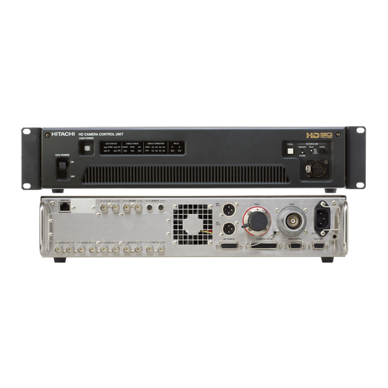
Page 18: Facility Names And Functions (Front) Cu-Hd1300F-S3
Facility names and functions (Front) CU-HD1300F-S3 【CCU】The strength of the arriving light signal from CCU POWER switch CCU to Camera Head is indicated by LED. CCU power on/off switch. CAMERA POWER switch The switch lights during camera power on. YELLOW GREEN2 GREEN1 When the camera power is off, only one... -
Page 19: Facility Names And Functions (Rear) Cu-Hd1300F-S3
CU-HD1300F-S3 Facility names and functions (Rear) Select the HD-SDI or SD-SDI by the user TALK ON/OFF switch function menu. Intercom microphone on/off switch. The character is superimposed in PIX output. 10 INTERCOM LEVEL control Adjusts intercom listening volume. 13 High Speed OUTPUT connectors (BNC) 11 Intercom connector (XLR,5P) Outputs 2 sets of three times high speed Connection for optional MT-12MF headset. - Page 20 Input for AC power supply. Inputs AC input range is 100V to 240V, 47 to 63Hz, Output VF or RET OUT x1 HD-SDI2x1 with auto-sensing. (SK-HD1300-S3) (CA-HF1300-S3) Output RET-1/2 switch Selected by CCU connector 23 MIC OUT (XLR 3pin) (CA-HF1300-S3)...
-
Page 21: System Configuration: Mode Selection Method
1 9 : 5 8 CABLE TYPE OPT HYBRID Optical fiber operation is available combined with camera adaptor (CA-HF1300-S3). Use a HFOC (Hybrid Fiber-Optic Cable) between the camera adaptor and CCU. OPT SINGLE Optical fiber operation is available combined with camera adaptor (CA-HF1300-S3). -
Page 22: System Configuration: Hybrid Fiber Optic Cable Mode
SU-1000 Camera stand-alone operation By supplying DC12V power to the DC IN connector of CA-HF1300-S3 without optical cable, the camera works as stand-alone. In the stand-alone operation, camera video is output from MON output of camera head and HD-SDI1 output of... - Page 23 Supply external power locally to the camera adaptor to extend the maximum cable distance. The setup is following procedure. 1) Connect the camera adapter CA-HF1300-S3 and camera control unit CU-HD1300F-S3 with single mode fiber cable. 2) Power up the CU-HD1300F-S3.
- Page 24 System configuration diagram Camera system connections CU-HD1300F-S3 is connected to camera head SK-HD1300-S3 attached with camera adaptor CA-HF1300-S3 via triax cable. Also, it is connected to camera adaptor CA-HF1300-S3 via optical fiber cable. RU-1500 : The remote control unit RU-1500 can control above system.
-
Page 25: Function Menu
Function menu Function menu Connect the camera control unit (RU-1500) or the setup control unit (SU-1000) to the CU-UHD4000 to display the function menus on PIX video output. The function menus include the CCU menu to adjust the CCU and the camera menu to adjust a camera. See each Operation Instruction for RU-1500 and SU-1000 operation. - Page 26 Function menu CCU MENU DISPLAY Press the MENU button of camera control panel (RU-1500) or the setup control unit (SU-1000) to open MENU SELECT screen, and then move to the camera head menu or the CCU menu. When Color-bars is ON, press the MENU button to open the CCU menu directly. CCU MENU TREE MENU SELECT Moves to the camera head menu.
- Page 27 Function menu CU-FUNCTION menu ■CU-FUNCTION Item Setting Factory setting Description BUZZER :ENABLE BUZZER ENABLE, ENABLE Sets buzzer operation during call input. SDI AUDIO :OFF CCU ID : 1 DISABLE ENABLE : Buzzer sounds. *CABLE TYPE: OPT HYBRID PARA MODE :OFF DISABLE : Buzzer does not sound.
- Page 28 RET.1 Assigns the return video signal to CH1 selected when CH3 :RET.3 CH4 :RET.4 RET.2, CA-HF1300-S3 RET switch is set to 1. CA HD-SDI :RET.B1 RET.3, RET.2 Assigns the return video signal to CH2 selected when RET.4 ASSIGNMENT: CA-HF1300-S3 RET switch is set to 2.
- Page 29 Function menu 3.1. ASSIGNMENT menu ■ASSIGNMENT Item Setting Factory Description SELECT TYPE setting RET.1 :1080i/PsF/P RET.2 :1080i/PsF/P RET.1 1080p, Assigns the TV format to RET.1. RET.3 :1080i/PsF/P RET.4 :1080i/PsF/P 1080i/PsF/P, RET.2 Assigns the TV format to RET.2. RET.B1 :1080i/PsF/P 720p, RET.B2...
- Page 30 Function menu PIX DISPLAY menu ■PIX DISPLY Item Setting Factory Description ND FILTER :ON setting CC FILTER :ON IRIS :ON ND FILTER OFF, ON Displays ND filter type on PIX OUT. ( For more detail of this, CAM ID :ON see page 25.) CCU...
- Page 31 Function menu SD DTL menu ■SD DTL Item Setting Factory Description SD DTL :ON setting H GAIN : 0 V GAIN : 0 SD DTL OFF, ON Enable the detail effect specialized for SDTV. H CRISP :-128 V CRISP :-128 H GAIN -128 to +127 Adjusts the horizontal detail level.
- Page 32 Function menu LAN SETTING menu ■LAN SETTING Item Setting Factory setting Description IP :192.168. 1. 75 The current IP address is displayed. CONF>:192.168. 1. 75 SUBNET :255.255. 0. 0 CONF CONF>:255.255. 0. 0 Press button to open IP SETTING submenu. GATEWAY:192.168.
- Page 33 Function menu 10.2. SUBNET SETTING MENU ■SUBNET SETTING Item Setting Factory Description SUBNET :255.255. 255. 0 setting SEND :255.255. 255. 0 EDIT SUBNET The current SUBNET address of CCU is displayed. OCTET1:255 OCTET2:255 The expression of SUBNET address is: OCTET3:255 OCTET4:...
- Page 34 Function menu Status indication When each item are set ON on PIX DISPLAY menu, the optical filter (ND/CC) and F-number of lens iris are displayed at the bottom of the PIX screen. FILTER Mode CLEAR ND FILTER 1/4 ND 1/16 ND 1/64 ND 3200 K CC(Color...
-
Page 35: Cable Check, Warning Indication
Cable check, Warning indication Cable check: Optical system CU-HD1300F-S3 automatically checks the condition of optical cable, and shows the results on both PIX OUT screen and LED indicators on front panel at start-up. If any troubles are detected, the camera power might be forced to shut down for safety. -
Page 36: Warning Indication
PIX OUT:SUPPLY DC12V IN CX CA-HF1300-S3 needs external power. Connect external power to CA-HF1300-S3. PIX OUT:CAM HEAD PWR OFF CCU does not supply power to CA-HF1300-S3. PIX OUT:CCU FAN ALARM!! The CCU FAN is abnormal. The FAN stops, or rotary speed declines by deterioration. -
Page 37: Backup Battery Replacement
Backup battery replacement Backup battery replacement The backup battery is already mounted at the factory. If the time/date can not maintain accurate information, the alarm message “BACKUP BATT EMPTY” is shown on PIX OUT for about 6 seconds at start-up. In this case, the battery should be replaced, and the date and time should be adjusted at the TIME/DATE menu. -
Page 38: Service Information
Service information CU-HD1300F-S3 Connector pin diagrams INTERCOM (5 pin XLR female:HA16PRH-5S) MIC OUT 1,2 (3 pin XLR male: HA16RM-3PE(76)) Combined connector:5pin XLR male Combined connector:3pin XLR female PUSH Signal Signal TALK (C) MIC GND TALK (H) MIC(H) IN RECEIVE (C) MIC(C) IN RECEIVE L (H) RECEIVE R(H) - Page 39 Service information CU-HD1300F-S3 COMMUNICATION (25pin D-sub female:RDBD-25S-LNA(4-40)(55)) Combined connector: 25pin D-sub male Plug CCU mainframe Signal SYS2 SYS1 SYS0 PD OUT (C) 2W : OUT/IN(C) PD OUT (H) 2W : OUT/IN(H) PD SHIELD PD IN (C) 2W : NC PD IN (H) 2W : NC ENG OUT (C) 2W : OUT/IN(C)
- Page 40 Service information CU-HD1300F-S3 MIC REMOTE (15pin D-sub female: RDAD-15S-LNA(4-40)(55)) Combined connector: 15pin D-sub male Plug CCU mainframe SW ON :Lo Signal +5V OUT (200mA max) SW OFF:Hi TALLY GND 100kΩ G TALLY OUT R TALLY OUT MIC1 GAIN CTL2 MIC1 GAIN CTL1 MIC1 GAIN CTL0 MIC SEL1 MIC2 GAIN CTL2...
- Page 41 Service information CU-HD1300F-S3 WFM CONTROL (15pin female:YKF42-8043N) Combined connector: 15pin D-sub male Plug CCU mainframe Signal ← WFM CTL0 ← WFM CTL1 ← WFM CTL2 ← WFM CTL3 ← WFM CTL4 ← WFM CTL5 ← WFM CTL6 ← WFM CTL7 SHIELD MODE CTL0 CTL1 CTL2 CTL3 CTL4 CTL5 CTL6 CTL7...
- Page 42 Change a switch setup of a camera adaptor and a camera control unit at the time of carbon type headset use. Turn off the power, when you make setting change. Camera Head Camera Adaptor SK-HD1300-S3 CA-HF1300-S3 Camera Control Unit CU-HD1300F-S3 Optical Fiber Cable Headset (Carbon)
- Page 43 Service information 1.1 CU-HD1300F-S3 The Intercom setting for carbon type headset (1) Loosen two screws of the front panel and open a panel. (2) Set up the switch in a unit according to the headset to be used. (3) Close the front panel and tighten a two-place screw.
-
Page 44: External View
External View CU-HD1300F-S3 外観図 (Unit: mm) -
Page 45: Specifications
Specifications Camera Control Unit CU-HD1300F-S3 1x BNC, B-BST 0.45 Vp-p / 75Ω ( loop through ) Genlock HDTV tri-level sync 0.60 Vp-p / 75Ω ( loop through ) RETURN IN(1/2/3/4) 4x BNC, 3G-SDI or HD-SDI or SD-SDI ・1080p SMPTE424/425 Level-A RETURN B IN(1/2) ・1080i/720p SMPTE292M ・SD SDI: SMPTE259M-C... - Page 46 Specifications Accessories Remote control unit (RU-1500JY) Setup control unit ( SU-1000) Standard Composition Camera Control Unit CU-HD1300F-S3 1 Code Set(U/J) WC0051(0234-0089A 2.5M) (8488057) 1 Code Set(E) VM0306B;VM0303B 2.5M (BBZ0399) Operation Manual CU-HD1300F-S3 O/M Connector HDBB-25P (8AAE000854) 1 Plug Case HDB-CTH(4-40)(10) (JYHS003) 1...