Table of Contents
Quick Links
Table of Contents

Related Manuals for AEG ID ACM 9


Summary of Contents for AEG ID ACM 9
- Page 1 Manual ACM 9 ARE i9...
-
Page 2: Table Of Contents
Version: 02 Manual ACM 9 - ARE i9 release Page: 2 / 43 Introduction ..............................5 ACM 9 ................................6 Hardware ............................... 6 2.1.1 Dimensions ............................6 2.1.2 Protection Class ..........................6 2.1.3 Connectivity ............................7 2.1.4 Grounding ............................9 Firmware ............................. - Page 3 Version: 02 Manual ACM 9 - ARE i9 release Page: 3 / 43 3.2.12 VSAVE ............................21 3.2.13 INIT .............................. 21 3.2.14 Error messages ........................... 22 Firmware ARE i9 LF ..........................23 3.3.1 Instruction Set ..........................23 3.3.2 General format of instruction set ....................23 3.3.3 VER ..............................
- Page 4 Version: 02 Manual ACM 9 - ARE i9 release Page: 4 / 43 3.4.12 Error messages ........................... 35 LED instruction set ..........................36 3.5.1 LED Standby (LSTB) ........................37 3.5.2 LED Reading (LGT) ......................... 37 3.5.3 LED Transponder number successfully read (LRD) ..............38 3.5.4 LED No Read (LNRD) ........................
-
Page 5: Introduction
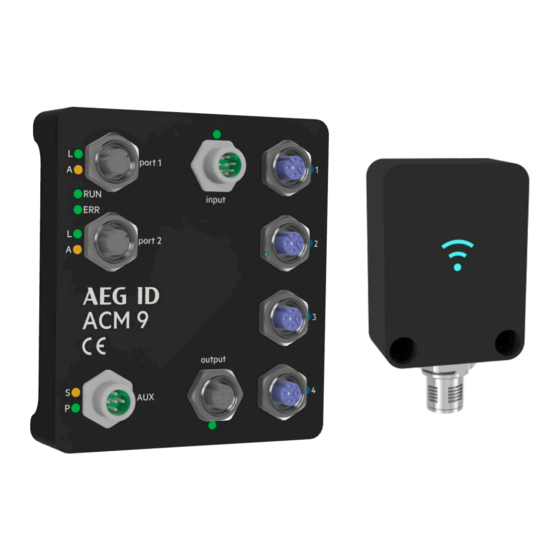
ACM 9 Industrial Ethernet (EtherCAT®, EtherNet/IP™, Profinet®), AEG ID Communication Module, provides Industrial Ethernet connectivity for ARE i9, AEG ID RFID reader family. Both units are dedicated to each other, none of the two is meant to be used without the other. Four ARE i9 units can be hooked up to one ACM 9. -
Page 6: Acm 9
Version: 02 Manual ACM 9 - ARE i9 release Page: 6 / 43 2. ACM 9 ACM 9 Industrial Ethernet communication module supports Industrial Ethernet connectivity. EtherCAT, EtherNet/IP and Profinet are implemented (only one at a time). ACM 9 has 2 Industrial Ethernet ports, 4 serial ports dedicated to ARE i9 reader family, 4 digital inputs and 4 digital outputs, both linked to their respective reader port. -
Page 7: Connectivity
Version: 02 Manual ACM 9 - ARE i9 release Page: 7 / 43 2.1.3 Connectivity 4 digital Inputs Industrial Serial Port 1 ARE i9 Ethernet Port 1 Industrial Serial Port 2 ARE i9 Ethernet Port 2 Serial Port 3 ARE i9 Auxiliary Port Serial Port 4 ARE i9 Power + RS 232... - Page 8 Version: 02 Manual ACM 9 - ARE i9 release Page: 8 / 43 Industrial Ethernet Port (Port 1, Port 2) M12 socket 4 Pin female D-coded (standard Industrial Ethernet) PIN 1 – TD+ PIN 2 – RD+ PIN 3 – TD- PIN 4 –...
-
Page 9: Grounding
Version: 02 Manual ACM 9 - ARE i9 release Page: 9 / 43 Digital Inputs (input) M12 socket 8-Pin male A-coded PIN 1 – Input for serial port 1 PIN 2 – Input for serial port 2 PIN 3 – Input for serial port 3 PIN 4 –... -
Page 10: Firmware
Version: 02 Manual ACM 9 - ARE i9 release Page: 10 / 43 2.2 Firmware ACM 9 uses 32 Byte cyclic input data and 32 Byte cyclic output data. 2.2.1 Industrial Ethernet description files Profinet: File ACM9_PNS_V1_1_0.xml contains Profinet description for ACM 9. EtherCAT: File ACM9_ECS_V1_1_0.xml contains EtherCAT description for ACM 9. -
Page 11: Acm 9 Error Messages
Version: 02 Manual ACM 9 - ARE i9 release Page: 11 / 43 2.2.4 ACM 9 error messages ACM 9 itself has the following error messages. Wrong channel number (Error code #65) A wrong channel number is set to the master output data. Valid channel numbers are from ‘1’ to ‘4’. Hex: …... -
Page 12: Error Messages Coming Through From Are I9
Version: 02 Manual ACM 9 - ARE i9 release Page: 12 / 43 ACM 9 sets master input data to: Hex: … ASCII:‘#’ ‘6’ ‘7’ Meaning Change Serial Error Text counter interface character port 2.2.5 Error messages coming through from ARE i9 Other error messages can be generated by the reader, if the reader command is wrong. -
Page 13: Are I9
Version: 02 Manual ACM 9 - ARE i9 release Page: 13 / 43 3. ARE i9 ARE i9 is a small industrial RFID reader that is available as a LF - SEMI Industry, LF and HF version. ARE i9 LF hdx - SEMI Industry works with LF hdx transponders. ARE i9 LF works with (all) low frequency transponders ASK, PSK, FSK, @ 125 KHz, 128kHz and 134.2 kHz (ISO 11784/11785). -
Page 14: Connectivity
Version: 02 Manual ACM 9 - ARE i9 release Page: 14 / 43 3.1.3 Connectivity ARE i9 is connected via its M12, 5-Pin male A-coded plug. Power supply as well as communication is provided by ACM 9, communication module. Do not use any other means of powering or communicating to ARE i9 other than an ACM 9 module, otherwise ARE i9 will be damaged. -
Page 15: Transponder Orientation Relative To Are I9
Version: 02 Manual ACM 9 - ARE i9 release Page: 15 / 43 3.1.4 Transponder orientation relative to ARE i9 Disk parallel (recommended) Glass transponder perpendicular (recommended) Direction of travel The highest read range is achieved right above the center of ARE i9 front side. Disk Perpendicular Glass parallel Direction of... -
Page 16: Read Range For Semi Application
Version: 02 Manual ACM 9 - ARE i9 release Page: 16 / 43 3.1.5 Read range for SEMI application Glass transponder Texas Instruments RI-TRP-DR2B Glass transponder perpendicular (recommended) 120mm 100mm 100mm The highest read range is achieved right above the center of ARE i9 front side. Glass parallel 80mm 80mm... -
Page 17: Firmware Are I9 Lf Hdx - Semi Industry
Version: 02 Manual ACM 9 - ARE i9 release Page: 17 / 43 3.2 Firmware ARE i9 LF hdx - SEMI Industry ARE i9 LF hdx - SEMI Industry reads low frequency hdx transponders, typically in glass transponder format 4mmx34mm. 3.2.1 Instruction Set Communication with ARE i9 LF SEMI Industry is based on a simple ASCII text based protocol. -
Page 18: Tor
Version: 02 Manual ACM 9 - ARE i9 release Page: 18 / 43 3.2.4 GT GT – Get Tag GT is used to retrieve the transponder UID. Input format: GTHex: ASCII: ‘G’ ‘T’ Output (example): 1234567812345678 Hex: ASCII: ‘1’... -
Page 19: Nid
Version: 02 Manual ACM 9 - ARE i9 release Page: 19 / 43 3.2.6 NID NID – Double reading of UID to ensure consistency in EMV polluted environment. NID is used to double read a transponder UID to ensure consistency in an EMV polluted environment. The transponder UID is transmitted only after two consecutive reads of the same UID Parameters: 0 –... - Page 20 Version: 02 Manual ACM 9 - ARE i9 release Page: 20 / 43 3.2.8 CN CN – Filter no read from being transmitted via interface. CN is used in those cases, where no read information ‘XXXXXXXXXXXXXXXX’ is not to appear on the interface. Only valid transponder UID will be transmitted.
-
Page 21: Vsave
Version: 02 Manual ACM 9 - ARE i9 release Page: 21 / 43 3.2.11 LD LD – lock memory page LD is used to lock a particular memory page from a transponder in the field. Input format: LD1 Hex: ASCII: ‘L’... -
Page 22: Error Messages
Version: 02 Manual ACM 9 - ARE i9 release Page: 22 / 43 The following parameters are set: TOR 50 LRD 01001 MD 2 LNRD 10001 CID 0 LERR 10011 CN 0 LED 1 LSTB 01101 LRT 30 LGT 01111 LPA 00000 3.2.14 Error messages Error messages and protocol errors are acknowledged by ARE i9 using an error code. -
Page 23: Firmware Are I9 Lf
Version: 02 Manual ACM 9 - ARE i9 release Page: 23 / 43 3.3 Firmware ARE i9 LF ARE i9 LF works with (all) low frequency transponders in ASK, PSK and FSK modulation. Please see chapter 3.3.13 for details on which transponder chips are implemented. Depending on the selected algorithms, not all instructions below make sense so only those which do work accordingly (e.g. -
Page 24: Tor
Version: 02 Manual ACM 9 - ARE i9 release Page: 24 / 43 3.3.4 GT GT – Get Tag GT is used to retrieve the transponder UID. Input format: GTHex: ASCII: ‘G’ ‘T’ Output (example): 12345678 Hex: ASCII: ‘1’... -
Page 25: Nid
Version: 02 Manual ACM 9 - ARE i9 release Page: 25 / 43 3.3.6 NID NID – Double reading of UID to ensure consistency in EMV polluted environment. NID is used to double read a transponder UID to ensure consistency in an EMV polluted environment. The transponder UID is transmitted only after two consecutive reads of the same UID Parameters: 0 –... - Page 26 Version: 02 Manual ACM 9 - ARE i9 release Page: 26 / 43 3.3.8 CN CN – Filter no read from being transmitted via interface. CN is used in those cases, where no read information ‘XXXXXXXX’ is not to appear on the interface. Only valid transponder UID will be transmitted.
-
Page 27: Vsave
Version: 02 Manual ACM 9 - ARE i9 release Page: 27 / 43 3.3.11 VSAVE VSAVE – Save parameter permanently in ARE i9 flash memory VSAVE is used to save parameters permanently in flash memory of ARE i9 to be available after power on. Input format: VSAVE... -
Page 28: Error Messages
Version: 02 Manual ACM 9 - ARE i9 release Page: 28 / 43 3.3.13 Error messages Error messages and protocol errors are acknowledged by ARE i9 using an error code. The format is described below:'#' Example error #02 (wrong parameter) Hex: ASCII:... -
Page 29: Log (Em4305 Chip Specific)
Version: 02 Manual ACM 9 - ARE i9 release Page: 29 / 43 3.3.15 LOG (EM4305 chip specific) EM 4305 EM 4305 is a multi purpose chip from EM microelectronic Marin. It features 512 bit memory and can be configured to transmit in ASK 64-bit Manchester, PSK1, Trovan, ISO 11784/85 fdx-b, pigeon mode among others or work as a simple memory chip. -
Page 30: Ld (Em4305 Chip Specific)
Version: 02 Manual ACM 9 - ARE i9 release Page: 30 / 43 3.3.17 LD (EM4305 chip specific) After the chip is configured correctly, it may be necessary to lock specific memory blocks of EM 4305. Memory blocks from 0 to 13 can be locked. -
Page 31: Firmware Are I9 Hf
Version: 02 Manual ACM 9 - ARE i9 release Page: 31 / 43 3.4 Firmware ARE i9 HF 3.4.1 Instruction Set Communication with ARE i9 is based on a simple ASCII text based protocol. The host sends text based telegrams to ARE i9 and receives text based telegrams back containing the answer to the query. -
Page 32: Tor
Version: 02 Manual ACM 9 - ARE i9 release Page: 32 / 43 3.4.4 GT GT – Get Tag GT is used to retrieve the transponder UID. Input format: GTHex: ASCII: ‘G’ ‘T’ Output (example): 12345678 Hex: ASCII: ‘1’... -
Page 33: Cid
Version: 02 Manual ACM 9 - ARE i9 release Page: 33 / 43 3.4.6 CID CID – Filter same UID numbers to transmit only once via interface CID is used to filter multiple read transponder UID to transmit only once via interface. There needs to be one different Transponder UID read before the same number will be transmitted again. -
Page 34: Vsave
Version: 02 Manual ACM 9 - ARE i9 release Page: 34 / 43 3.4.8 RD RD – Read transponder memory page RD is used to read an individual memory page from a transponder in the field. Input format: RD1 Hex: ASCII: ‘R’... -
Page 35: Init
Version: 02 Manual ACM 9 - ARE i9 release Page: 35 / 43 3.4.11 INIT INIT – Restore standard parameters. Command needs to be followed up by VSAVE in order to permanently store the parameters. Input format: INITHex: ASCII: ‘I’... -
Page 36: Led Instruction Set
Version: 02 Manual ACM 9 - ARE i9 release Page: 36 / 43 3.5 LED instruction set ARE i9 employs a multi-color LED to signal different modes. Basically below colors can be created: The user can choose any color apart from white. This color is reserved for setup help functionality as described below. The following modes use a distinct color each. -
Page 37: Led Standby (Lstb)
Version: 02 Manual ACM 9 - ARE i9 release Page: 37 / 43 Default colors are shown with the instructions. 3.5.1 LED Standby (LSTB) Standby color is Cyan, no flash. Input format: LSTB01101 Hex: ASCII: ‘L’ ‘S’ ‘T’ ‘B’ ... -
Page 38: Led Transponder Number Successfully Read (Lrd)
Version: 02 Manual ACM 9 - ARE i9 release Page: 38 / 43 3.5.3 LED Transponder number successfully read (LRD) Successful read color is green, no flash Input format: LRD01001 Hex: ASCII: ‘L’ ‘R’ ‘D’ ‘0’ ‘1’ ’1’ ... -
Page 39: Led Error (Lerr)
Version: 02 Manual ACM 9 - ARE i9 release Page: 39 / 43 3.5.6 LED Error (LERR) Error color is red, flashing Input format: LERR10011 Hex: ASCII: ‘L’ ‘E’ ‘R’ ‘R’ ‘1’ ’1’ Output: 10011 Hex: ASCII: ‘1’... -
Page 40: Led Process Status
Version: 02 Manual ACM 9 - ARE i9 release Page: 40 / 43 3.5.8 LED Process status LED Process status is used to indicate the status of a process, after it is performed. Successful Process LED color is green, not flashing Input format: LPS... -
Page 41: Led (De)Activate Led Functionality (Led)
Version: 02 Manual ACM 9 - ARE i9 release Page: 41 / 43 3.5.10 LED (De)activate LED functionality (LED) In order to deactivate (or activate) the LED functionality, LED instruction is used. Input format: LEDParameter Hex: ASCII: ‘L’ ‘E’ ‘D’ ... -
Page 42: System Implementation
Version: 02 Manual ACM 9 - ARE i9 release Page: 42 / 43 4. System implementation 4.1 Power supply SEMI industry uses hdx LF RFID technology. This particular method relies on field gaps, where the RFID field is switched off. In this gap the transponder answers with its code. - Page 43 AEG Identifikationssysteme GmbH Hörvelsinger Weg 47 89081 Ulm Tel.: +49 731 14 00 88 – 0 Email: [email protected] Web: www.aegid.de...