Mitsubishi Electric MELSEC iQ-R Series User Manual
Server module, startup, mx opc ua module configurator-r
Hide thumbs
Also See for MELSEC iQ-R Series:
- Programming manual (2110 pages) ,
- User manual (760 pages) ,
- Reference manual (498 pages)

Related Manuals for Mitsubishi Electric MELSEC iQ-R Series


Summary of Contents for Mitsubishi Electric MELSEC iQ-R Series
- Page 1 MELSEC iQ-R OPC UA Server Module User's Manual (Startup) -RD81OPC96 -SW1DND-ROPCUA-E (MX OPC UA Module Configurator-R)
-
Page 3: Safety Precautions
SAFETY PRECAUTIONS (Read these precautions before using this product.) Before using this product, please read this manual and the relevant manuals carefully and pay full attention to safety to handle the product correctly. The precautions given in this manual are concerned with this product only. For the safety precautions for the programmable controller system, refer to MELSEC iQ-R Module Configuration Manual. - Page 4 [Design Precautions] WARNING ● Configure safety circuits external to the programmable controller to ensure that the entire system operates safely even when a fault occurs in the external power supply or the programmable controller. Failure to do so may result in an accident due to an incorrect output or malfunction. (1) Emergency stop circuits, protection circuits, and protective interlock circuits for conflicting operations (such as forward/reverse rotations or upper/lower limit positioning) must be configured external to the programmable controller.
- Page 5 [Design Precautions] WARNING ● Do not write any data to the "system area" and "write-protect area" of the buffer memory in the module. Also, do not use any "use prohibited" signals as an output signal from the CPU module to each module.
- Page 6 [Installation Precautions] WARNING ● Shut off the external power supply (all phases) used in the system before mounting or removing the module. Failure to do so may result in electric shock or cause the module to fail or malfunction. [Installation Precautions] CAUTION ●...
- Page 7 [Wiring Precautions] CAUTION ● Individually ground the FG and LG terminals of the programmable controller with a ground resistance of 100 ohms or less. Failure to do so may result in electric shock or malfunction. ● Use applicable solderless terminals and tighten them within the specified torque range. If any spade solderless terminal is used, it may be disconnected when the terminal screw comes loose, resulting in failure.
- Page 8 [Wiring Precautions] CAUTION ● Programmable controllers must be installed in control panels. Connect the main power supply to the power supply module in the control panel through a relay terminal block. Wiring and replacement of a power supply module must be performed by qualified maintenance personnel with knowledge of protection against electric shock.
- Page 9 [Startup and Maintenance Precautions] CAUTION ● When connecting an external device with a CPU module or intelligent function module to modify data of a running programmable controller, configure an interlock circuit in the program to ensure that the entire system will always operate safely. For other forms of control (such as program modification, parameter change, forced output, or operating status change) of a running programmable controller, read the relevant manuals carefully and ensure that the operation is safe before proceeding.
- Page 10 [Startup and Maintenance Precautions] CAUTION ● Before handling the module, touch a conducting object such as a grounded metal to discharge the static electricity from the human body. Failure to do so may cause the module to fail or malfunction. [Operating Precautions] CAUTION ●...
-
Page 11: Conditions Of Use For The Product
CONDITIONS OF USE FOR THE PRODUCT (1) Mitsubishi programmable controller ("the PRODUCT") shall be used in conditions; i) where any problem, fault or failure occurring in the PRODUCT, if any, shall not lead to any major or serious accident; ii) where the backup and fail-safe function are systematically or automatically provided outside of the PRODUCT for the case of any problem, fault or failure occurring in the PRODUCT. -
Page 12: Introduction
Before using this product, please read this manual and the relevant manuals carefully and develop familiarity with the functions and performance of the MELSEC iQ-R series programmable controller to handle the product correctly. Please make sure that the end users read this manual. -
Page 13: Table Of Contents
CONTENTS SAFETY PRECAUTIONS ..............1 CONDITIONS OF USE FOR THE PRODUCT . - Page 14 CHAPTER 7 INSTALLATION AND UNINSTALLATION Installation Procedure..............55 Environment after installation .
-
Page 15: Relevant Manuals
• Installation For details, refer to the following: MELSEC iQ-R Module Configuration Manual e-Manual refers to the Mitsubishi Electric FA electronic book manuals that can be browsed using a dedicated tool. e-Manual has the following features: • Required information can be cross-searched in multiple manuals. -
Page 16: Terms
A generic term for MELSEC-Q series CPU modules and MELSEC-Q series C Controller modules. RCPU A generic term for MELSEC iQ-R series CPU modules and MELSEC iQ-R series C Controller modules. RnENCPU A generic term for R04ENCPU, R08ENCPU, R16ENCPU, R32ENCPU, and R120ENCPU. -
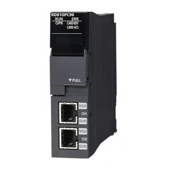
Page 17: Chapter 1 Part Names
PART NAMES This chapter shows the part names of an OPC UA server module. (10) Name Description RUN LED Indicates the operating status. • ON: In operation • Flashing: In selection for online module change • OFF: Watchdog timer error (hardware failure), module replacement allowed in the process of the online module change ERR LED Indicates the error status. - Page 18 Name Description *1,*2 Ethernet port (CH1, CH2) A port for connecting an OPC UA server module to 10BASE-T/100BASE-TX/1000BASE-T. (An OPC UA server module distinguishes among 10BASE-T, 100BASE-TX, and 1000BASE-T depending on an external device.) Dot matrix LED display mode switch A switch for switching the display of the dot matrix LED.
-
Page 19: Chapter 2 Specifications
SPECIFICATIONS This chapter explains the specifications of an OPC UA server module. Performance Specifications This section shows the performance specifications of an OPC UA server module. Hardware specification Item Specification SD memory card slot Interface SD memory card/SDHC memory card (2 GB to 16 GB) Power supply +3.3 VDC, up to 200 mA Ethernet port... -
Page 20: Software Specification
Software specification Item Description Reference OPC UA specification Specification for a supported OPC UA server. Page 18 OPC UA server specification Operation Basic operation Basic specification such as operations and time information handling Page 19 Operation specification specification specification Device memory input/ Specification for access to devices in modules such as a CPU module. - Page 21 Item Details Security Security User Name Password Security Certificate Validation Security None Security None CreateSession ActivateSession Security Basic 128Rsa15 Security Encryption Required Security Signing Required Security Default ApplicationInstanceCertificate Security User X509 Operation specification Item Specification Basic operation specification Time information Time Acquired from a CPU module (CPU No.1 in a multiple CPU system).
- Page 22 Item Specification Structure specification Structure definition Maximum number of settings Maximum number of members that can be set for one structure Maximum number of layers Data type of a member • INT • UINT • REAL • LREAL • BOOL •...
-
Page 23: Access Specifications For A Cpu Module
Access Specifications for a CPU Module This section shows the access specifications for a CPU module. Accessible CPU modules Series Model name RCPU Programmable controller R00CPU, R01CPU, R02CPU, R04CPU, R04ENCPU, R08CPU, R08ENCPU, R16CPU, R16ENCPU, R32CPU, R32ENCPU, R120CPU, R120ENCPU Process CPU R08PCPU, R16PCPU, R32PCPU, R120PCPU Safety CPU R08SFCPU, R16SFCPU, R32SFCPU, R120SFCPU... -
Page 24: Accessible Routes
Accessible routes The following figure shows accessible routes from an OPC UA server module. : Access route from an OPC : Connection from an Ethernet : Connection by specifying : Connection by UA server module port of an OPC UA server module the network number and the station specifying the start I/O No. - Page 25 Own station (control CPU, another CPU in a multiple CPU system) The following table shows the accessibility to a CPU module of a station that an OPC UA server module is mounted. : Accessible, : No combination Access route Access target device type (series) RCPU QCPU (Q mode) LCPU...
- Page 26 Another station via a single network ■Access via an Ethernet port of an OPC UA server module A target device can be accessed via an Ethernet port of an OPC UA server module in the status where the target device is connected to a network.
- Page 27 ■Access by specifying the network number and the station number of a target station A target device can be accessed via a relay station when the target device is connected within eight networks from a station, on which an OPC UA server module is mounted, and can be identified by the network number and the station number (or CPU number).
- Page 28 Another station via a co-existence network ■Access by specifying the network number and the station number via another station on CC- Link The following table shows the accessible route to a target station from a station, on which an OPC UA server module is mounted, by specifying the network number and the station number of the target station.
-
Page 29: Accessible Devices
Accessible devices The following table shows the accessible devices. : Accessible, : Not accessible, : No device Device name (device) Access target device type (series) RCPU QCPU (Q mode) LCPU Programmable C Controller Programmable C Controller Programmable controller CPU/ module controller CPU/ module controller CPU... - Page 30 Device name (device) Access target device type (series) RCPU QCPU (Q mode) LCPU Programmable C Controller Programmable C Controller Programmable controller CPU/ module controller CPU/ module controller CPU Process CPU/ Process CPU Safety CPU Link direct device Link input (Jn\X) Link output (Jn\Y) ...
-
Page 31: Access Units
Access units The following table shows the number of accessible device points (access units) in one process (one scanning) when accessing the device memory in a CPU module. The access units of a CPU module other than the following modules depend on the module type. Access target device type (series) Device reading Device writing... -
Page 32: Chapter 3 Function List
FUNCTION LIST This chapter shows the function lists of an OPC UA server module and the configuration tool. For details on the functions, refer to the following: MELSEC iQ-R OPC UA Server Module User's Manual (Application) Function List of an OPC UA Server Module This section shows the function list of an OPC UA server module. -
Page 33: Function List Of The Configuration Tool
Function List of the Configuration Tool This section shows the function list of the configuration tool. Function Description Address space setting Tree view To display address space information and each definition in a tree. function List view To display a child item of an item selected on the tree view in a list. Access target device communication To set a communication setting for an access target device. -
Page 34: Chapter 4 Procedure Before Operation
PROCEDURE BEFORE OPERATION This chapter shows the procedure before operation for using an OPC UA server module. 4 PROCEDURE BEFORE OPERATION... -
Page 35: Starting An Opc Ua Server Module And An Configuration Personal Computer
Starting an OPC UA Server Module and an Configuration Personal Computer OPC UA server module*1 Configuration personal computer Mount it on a base unit.*2 Install the configuration tool.*3 Switch the dot matrix LED display mode switch to the right (SHOW). Connect the OPC UA server module and the configuration personal computer on a 1:1 basis.*4 Turn the power of the system ON. - Page 36 Network setting for connection The following shows the network setting for a configuration personal computer when connecting the computer to an OPC UA server module via a hub. Operating procedure Set the same value for the network portion of the IP addresses for a configuration personal computer and an OPC UA server module.
-
Page 37: Configuration Tool
Startup method Operating procedure Select [MELSOFT] [MX OPC UA] [MELSEC iQ-R series OPC UA Server Module Configuration Tool] from Windows Start *1 Select [All apps] in the Start screen or [Start] [All Programs]/[All apps]. *2 Does not appear in Windows 8 or later. - Page 38 Screen configuration (1) Menu bar (2) Tree view (3) List view (4) Log view ■Menu configuration Item Description File To discard a project being edited and create a new project. Open Project To open a project file saved in a personal computer. Save To overwrite and save a project being edited in a file.
- Page 39 Item Description View Basic Function Bar To show/hide the buttons for basic functions. Online Operating Bar To show/hide the buttons for online operation. Status Bar To show/hide the status bar. To show/hide the log view. Large Icons To change the icons on the list view to the large ones. Small Icons To change the icons on the list view to the small ones.
- Page 40 ■Tree view Address space information and each definition are displayed in a tree. ■List view A child item of an item selected in the tree view is displayed in a list. Clicking the header of each column can sort items in ascending or descending order by comparing character strings. Note that clicking the header of the "Device"...
-
Page 41: Parameter Setting
Parameter Setting This section shows the mode setting of an OPC UA server module in the parameter setting of an engineering tool. For details on the parameter setting, refer to the following: MELSEC iQ-R OPC UA Server Module User's Manual (Application) Startup method Operating procedure Select [MELSOFT] ... - Page 42 Add an OPC UA server module. Item Description Module Type Select "Information Module." Module Name Select "RD81OPC96." Mounting Slot No. Select the slot number where an OPC UA server module is mounted. Start I/O No. Specification Select "Not Set" when not specifying the start I/O number of an OPC UA server module; otherwise, select "Set." Start I/O No.
-
Page 43: Sd Memory Card
SD Memory Card This section shows an SD memory card inserted and used in an OPC UA server module. For supported SD memory cards and considerations, refer to the following: Page 50 SD memory card (sold separately, required) Page 45 Considerations for using an SD memory card Operation for inserting an SD memory card The following shows the method for inserting an SD memory card. -
Page 44: Operation For Removing Or Replacing An Sd Memory Card
Operation for removing or replacing an SD memory card Make sure to stop the file access by following the procedure as shown below when removing or replacing an SD memory card. If the power is OFF and the file access is not stopped, turn the power ON and stop the file access. Start Is the power ON? Turn the power of the programmable controller ON. -
Page 45: File Access Stop Processing Method
File access stop processing method The following are the methods to stop file access. • Using the switch on the front of a module • Using the I/O (X/Y) signal Method by using the switch on the front of a module Press the SD memory card lock switch for one second or more. -
Page 46: Insertion/Removal Method Of An Sd Memory Card
Insertion/removal method of an SD memory card Make sure to stop the file access when removing or replacing an SD memory card. Insertion procedure Insert an SD memory card (1) straight into the SD memory card slot with its cutout pointed down. Make sure it is not uplifted after inserting it. -
Page 47: Considerations For Using An Sd Memory Card
Considerations for using an SD memory card SD memory card to be used Use a supported SD memory card. (Page 50 SD memory card (sold separately, required)) If another SD memory card is used, data in the SD memory card may be corrupted or the system may stop. When using an SD memory card used for other uses, make sure to format the card with the SD memory card diagnostic on the configuration tool. - Page 48 SD memory card format An SD memory card can be formatted with the SD memory card diagnostic on the configuration tool. (MELSEC iQ-R OPC UA Server Module User's Manual (Application)) Do not format an SD memory card with standard format commands of an operating system such as Windows. Files in an SD memory card Do not edit a file or folder in an SD memory card directly by inserting the card in a personal computer.
-
Page 49: Chapter 5 System Configuration
SYSTEM CONFIGURATION This chapter shows the system configuration of an OPC UA server module. System Configuration Overall system configuration The following figure shows the overall system configuration when using an OPC UA server module. Ethernet CC-Link IE Control, CC-Link IE Field, CC-Link, Ethernet ... (1) OPC UA client (2) SCADA (3) OPC UA server module... -
Page 50: System Configuration During Operation
System configuration during operation This section shows the system configuration when operating an OPC UA server module. Connection via a hub An OPC UA server module can be connected to a configuration personal computer via a hub in a local area network. The IP address of an OPC UA server module needs to be specified. - Page 51 Considerations for direct connection ■Connecting to a LAN line Do not perform communication by connecting to a LAN line directly. This may increase the line load and affect the communications of other devices. ■Connections which are not direct connections Do not set the direct connection in a configuration where a single OPC UA server module is connected to a single configuration personal computer via a hub as shown in the following figure.
-
Page 52: Connection Device
This section shows the connectable devices to an OPC UA server module. SD memory card (sold separately, required) One SD memory card is required for using an OPC UA server module. Use one of the following SD memory cards manufactured by Mitsubishi Electric. Model name Description... -
Page 53: Operating Environment
Operating Environment This section shows the operating environment of the configuration tool. Item Description Personal computer A personal computer on which Microsoft Windows operates Intel Core 2 Duo 2 GHz or more recommended Required memory 64-bit OS: 2 GB or more recommended 32-bit OS: 1 GB or more recommended Resolution 1024 ×... -
Page 54: Supported Software Package
Supported Software Package The following table shows the software package supporting an OPC UA server module. Software package Software version GX Works3 1.035M or later 5 SYSTEM CONFIGURATION 5.4 Supported Software Package... -
Page 55: Chapter 6 Wiring
WIRING This section shows the method for connecting an Ethernet cable to an OPC UA server module. For connectable Ethernet cables, refer to the following: Page 50 Ethernet (twisted pair) cable (sold separately) Wiring of an Ethernet Cable The following shows the connection and disconnection methods of an Ethernet cable. Connection procedure Check the insertion direction, and insert an Ethernet cable into an Ethernet port on the module until it clicks. -
Page 56: Wiring Considerations
Wiring Considerations • To establish a reliable system and fully use the functions of modules, a wiring that does not easily receive the effects of noise is required. • Sufficient safety measures must be taken when constructing the IEEE802.3 1000BASE-T/100BASE-TX/10BASE-T networks. -
Page 57: Chapter 7 Installation And Uninstallation
Storage destination of an execution file (when the installation destination is C:\Program Files (x86)\MELSOFT.) MELSEC iQ-R series OPC UA Server Module Configuration Tool C:\Program Files (x86)\MELSOFT\ROPCUA\MxOpcUaModuleConfiguratorR.exe *1 This setting is not required when the [Yes] button is selected on the screen below. -
Page 58: Environment After Installation
Maximum MX OPC UA Module Configurator-R Click [MELSOFT] [MX OPC UA] [MELSEC iQ-R series OPC UA Server Module Configuration Tool] from Windows Start *1 Select [All apps] in the Start screen or [Start] [All Programs]/[All apps]. *2 Does not appear in Windows 8 or later. -
Page 59: Chapter 8 Operation Example
OPERATION EXAMPLE This chapter shows the operation example of simple access in a system configuration including an OPC UA server module. The following example is for accessing the device (M0) of a CPU module from an OPC UA client. Setup System configuration This section shows the setting for configuring a sample system including the following devices and software. -
Page 60: Device Setup
Device setup This section shows the setup procedures of devices. Personal computer setting Operating procedure Install MX OPC UA Module Configurator-R. Set the IP address of a personal computer to '192.168.3.100'. This setting can be set on the "Internet Protocol Version 4 (TCP/IPv4) Properties" screen. Programmable controller system setting Operating procedure Mount a power supply module, CPU module, and OPC UA server module on a main base unit. -
Page 61: Setting Of An Opc Ua Server Module
Setting procedure Starting the configuration tool Start the configuration tool. Select [Start] [All Programs] [MELSOFT] [MX OPC UA] [MELSEC iQ-R series OPC UA Server Module Configuration Tool] from Windows Start. Setting a network Select [Tool] [Network Setting]. - Page 62 Setting the security Select [Tool] [Security Setting]. This setting is used as a default. Setting an access target device under the address space Select "Address Space" in the tree view. Select [Edit] [New Target Device]. Click the [OK] button. 8 OPERATION EXAMPLE 8.2 Setting of an OPC UA Server Module...
- Page 63 Setting a tag under the address space Select "Dev000" ( ) under "Address Space" in the tree view. Select [Edit] [New Data Tag]. Click the [OK] button. 8 OPERATION EXAMPLE 8.2 Setting of an OPC UA Server Module...
- Page 64 Setting a connection destination Select [Online] [Target Setting]. Enter a user name and a password, then click the [OK] button. The following are set by default. User name: RD81OPC96 Password: MITSUBISHI Uploading a certificate to the trust list Select [Online] [Manage Application Certificate]. Upload a client certificate to the trust list.
-
Page 65: Operation Check
Writing the setting Select [Online] [Write to OPC UA Server Module]. After completing the writing, reset the CPU module and start the OPC UA server module. If verifying a setting written to a module in the configuration tool the version of which is '1.01B' or later in the configuration tool the version of which is '1.00A', it cannot be verified correctly. -
Page 66: Appendix
APPENDIX Appendix 1 External Dimensions The following figures show the external dimensions of an OPC UA server module. 27.8 (Unit: mm) APPX Appendix 1 External Dimensions... - Page 67 MEMO APPX Appendix 1 External Dimensions...
-
Page 68: Index
INDEX ....21 Access specifications ..... . 50 Connection device . - Page 69 MEMO...
-
Page 70: Revisions
Japanese manual number: SH-081691-F This manual confers no industrial property rights of any other kind, nor does it confer any patent licenses. Mitsubishi Electric Corporation cannot be held responsible for any problems involving industrial property rights which may occur as a result of using the contents noted in this manual. -
Page 71: Warranty
WARRANTY Please confirm the following product warranty details before using this product. 1. Gratis Warranty Term and Gratis Warranty Range If any faults or defects (hereinafter "Failure") found to be the responsibility of Mitsubishi occurs during use of the product within the gratis warranty term, the product shall be repaired at no cost via the sales representative or Mitsubishi Service Company. -
Page 72: Trademarks
TRADEMARKS Intel is either a registered trademark or a trademark of Intel Corporation in the United States and/or other countries. Microsoft and Windows are either registered trademarks or trademarks of Microsoft Corporation in the United States and/or other countries. Unicode is either a registered trademark or a trademark of Unicode, Inc. in the United States and other countries. The company names, system names and product names mentioned in this manual are either registered trademarks or trademarks of their respective companies. - Page 74 SH(NA)-081693ENG-F(2004)KWIX MODEL: RD81OPC96-U-IN-E MODEL CODE: 13JX63 HEAD OFFICE : TOKYO BUILDING, 2-7-3 MARUNOUCHI, CHIYODA-KU, TOKYO 100-8310, JAPAN NAGOYA WORKS : 1-14 , YADA-MINAMI 5-CHOME , HIGASHI-KU, NAGOYA , JAPAN When exported from Japan, this manual does not require application to the Ministry of Economy, Trade and Industry for service transaction permission.