Dell EqualLogic PS6010 Hardware Maintenance
Storage arrays
Hide thumbs
Also See for EqualLogic PS6010:
- Hardware manual (50 pages) ,
- Quick reference manual (2 pages)

Related Manuals for Dell EqualLogic PS6010


Summary of Contents for Dell EqualLogic PS6010
- Page 2 All trademarks and registered trademarks mentioned herein are the property of their respective owners. Information in this document is subject to change without notice. Reproduction in any manner whatsoever without the written permission of Dell is strictly forbidden. November 2009...
-
Page 3: Table Of Contents
Table of Contents Preface ........................ iii Audience ......................iii Organization ....................iii Overview of Dell EqualLogic Products ............iv Related Documentation ..................vi Technical Support and Customer Service .............vii Warranty Information .................. viii Chapter 1 Basic Storage Array Information..........1-1 Array Front and Back Panels................ 1-1 Interpreting Operations Panel LEDs ............ - Page 4 PS6010 Hardware Maintenance Table of Contents Removing a Control Module ..............3-6 Installing a Control Module..............3-8 Replacing the MicroSD Card ..............3-11 Removing the MicroSD Card .............. 3-11 Inserting the MicroSD Card ..............3-12 Network Requirements and Recommendations ......... 3-13 Connecting Network Cables..............
-
Page 5: Preface
Preface This manual describes how to maintain the hardware for PS6010 storage arrays. Each array contains hot-swappable power supply and cooling modules, eight or sixteen RAID-protected disks, and single or dual hot-swappable control modules. With one or more PS Series arrays, you can create a PS Series group—a self- managing, iSCSI storage area network (SAN) that is affordable and easy to use, regardless of scale. -
Page 6: Overview Of Dell Equallogic Products
Appendix A, Environmental, Power, and Other Specifications, describes the specifications for a PS6010 array. Overview of Dell EqualLogic Products Thank you for your interest in Dell EqualLogic™ PS Series storage products. We hope you will find the PS Series products intuitive and simple to configure and manage. - Page 7 Preface PS6010 Hardware Maintenance - Multipath I/O Device Specific Module (MPIO DSM): Includes a connection awareness-module that understands PS Series network load balancing and facilitates host connections to PS Series volumes. - VSS and VDS Provider Services: Allows 3rd party backup software vendors to perform off-host backups.
-
Page 8: Related Documentation
Preface PS6010 Hardware Maintenance Related Documentation For detailed information about PS Series arrays, groups, volumes, array software, and host software, see the following documentation:... -
Page 9: Technical Support And Customer Service
PS6010 Hardware Maintenance Technical Support and Customer Service Dell’s support service is available to answer your questions about PS Series SAN arrays. If you have an Express Service Code, have it ready when you call. The code helps Dell's automated-support telephone system direct your call more efficiently. -
Page 10: Warranty Information
Preface PS6010 Hardware Maintenance • (Latin American countries) www.dell.com/la • (Canada only) www.dell.ca You can access Dell Support through the following Web sites: • support.dell.com • support.dell.com/EqualLogic • (Japan only) support.jp.dell.com • Europe only) support.euro.dell.com ( Warranty Information The PS6010 array warranty is included in the shipping box. For information about registering a warranty, visit support.dell.com/EqualLogic... -
Page 11: Chapter 1 Basic Storage Array Information
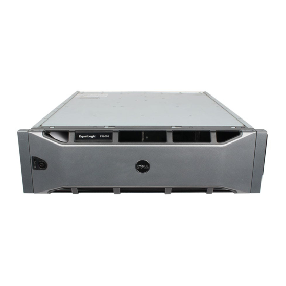
1 Basic Storage Array Information This chapter includes basic information about PS6010 storage arrays. Array Front and Back Panels The front of a PS6010 array is shown in Figure 1-1 and Figure 1-2. Figure 1-1: PS6010 Front Panel (with Bezel) Figure 1-2: PS6010 Front Panel (without Bezel) The disk drives are accessible from the front, after you remove the bezel. -
Page 12: Interpreting Operations Panel Leds
PS6010 Hardware Maintenance Basic Array Information Figure 1-3: PS6010 Back Panel Table 1-1: Back Panel Detail Description Item Description Power supply and cooling modules. The module on the right is 0, and the module on the left is 1. Control modules. The module on the right is 0, and the module on the left is 1. Operation panel LED. - Page 13 PS6010 Hardware Maintenance Basic Array Information For information about other array LEDs, see Interpreting Disk Drive LEDs on page 2-2, Interpreting Control Module LEDs on page 3-2, and Interpreting the LEDs on page 4-1. Figure 1-4: Operations Panel Table 1-2: Operations Panel Descriptions Callout Item Color...
-
Page 14: Warning Led Status Conditions
PS6010 Hardware Maintenance Basic Array Information Table 1-2: Operations Panel Descriptions (Continued) Callout Item Color Description Serial number label This label contains the serial number for your array. If you contact your PS Series support provider, you may need to provide this number. Warning LED Status Conditions When the Warning LED is flashing orange, one or more of the following has occurred:... -
Page 15: Using An Electrostatic Wrist Strap
PS6010 Hardware Maintenance Basic Array Information • Temperature exceeds upper or lower limit. • Control module cache has lost data. • A cooling module is not installed. • Both fans on a cooling module have failed. • Cache battery temperature is too high to charge battery. •... -
Page 16: Shutting Down And Restarting An Array
PS6010 Hardware Maintenance Basic Array Information Figure 1-5: Using an Electrostatic Wrist Strap 2. Fit the band closely around your wrist. 3. Connect the banan plug to ground, or attach the plug to the alligator clip and connect the clip to a grounded device such as an ESD mat or the metal frame of a grounded piece of equipment. - Page 17 Password: Welcome to Group Manager Copyright 2001-2009 Dell, Inc. group1> shutdown If you are using a serial connection to shut down an array, it is safe to turn off power when the “press any key” message appears. (Pressing any key will restart both control modules.)
-
Page 19: Chapter 2 Maintaining Disk Drives
2 Maintaining Disk Drives The array includes up to 16 hot-swappable disk drives, either Serial Attached SCSI (SAS) or Serial ATA (SATA). Disk drive maintenance topics apply to both SAS and SATA disk drives. Identifying Failed Disk Drives A disk drive failure is indicated by: •... -
Page 20: Interpreting Disk Drive Leds
PS6010 Hardware Maintenance Maintaining Disks Interpreting Disk Drive LEDs Figure 2-1 shows how disk drives are oriented and numbered in the array. Figure 2-1: Disk Drive Numbering The parts of a disk drive are shown in Figure 2-2 and described in Table 2-1. Figure 2-2: Disk Drive Detail Table 2-1: Disk Drive Detail Descriptions Callout... -
Page 21: Disk Drive Handling Requirements
PS6010 Hardware Maintenance Maintaining Disks Disk Drive Handling Requirements Handle disk drives as follows: • Store drives properly. Store replacement disk drives in the packaging in which they were shipped. Do not stack disk drives or place anything on top of a disk drive. -
Page 22: Replacing Disk Drives
PS6010 Hardware Maintenance Maintaining Disks • You can use disk drives with different sizes in an array. However, the smallest disk drive in the array will determine how much space can be used on each disk drive. For example, if the smallest disk drive is 400GB, only 400GB of space will be available for use on each disk drive. -
Page 23: Removing The Bezel
PS6010 Hardware Maintenance Maintaining Disks Removing the Bezel The bezel comes with a lock, which helps protect the disk drives from being tampered with or accidentally removed. To unlock and remove the bezel: 1. Insert the bezel key and turn it clockwise to unlock the bezel. See Figure 2-3. Figure 2-3: Unlocking the Bezel 2. -
Page 24: Removing A Disk Drive
PS6010 Hardware Maintenance Maintaining Disks Figure 2-4: Pushing Up the Bezel Release Latch 3. Hold the bezel and pull it away from the chassis. See Figure 2-5. Figure 2-5: Detaching the Bezel from the Chassis Removing a Disk Drive 1. Wear electrostatic protection when handling a disk drive. See Using an Electrostatic Wrist Strap on page 1-5. -
Page 25: Installing Disk Drives
PS6010 Hardware Maintenance Maintaining Disks 3. Grasp the handle and pull the disk drive 2.5 cm (1 inch) from the slot. See Figure 2-6. Figure 2-6: Removing a Disk Drive 4. Wait 30 seconds to allow the heads to land. (Does not apply when removing a blank carrier.) 5. -
Page 26: Installing The Bezel
PS6010 Hardware Maintenance Maintaining Disks 1. Hold the disk drive by the plastic carrier, with the handle release button to the left, and slide the disk drive partially into a slot. 2. Press the handle release button to release the handle. Open the handle. 3. - Page 27 PS6010 Hardware Maintenance Maintaining Disks 1. Facing the front of the array, fit the right side of the bezel into the right side of the chassis. 2. Push the bezel toward the chassis until the left side of the bezel engages with the chassis.
-
Page 29: Chapter 3 Maintaining Control Modules
3 Maintaining Control Modules A PS6010 array includes one or two hot-swappable Type 10 control modules. One functioning control module is required for array operation. You access control modules from the rear of the array. Control Modules The Type 10 control module includes: •... -
Page 30: Interpreting Control Module Leds
PS6010 Hardware Maintenance Maintaining Control Modules Interpreting Control Module LEDs Control modules have the following LEDs: • Between the serial port and the management port, three LEDs show the control module status and whether the control module is active or secondary. See Table 3-1 and callout 1 in Figure 3-1. -
Page 31: Identifying Control Module Failures
PS6010 Hardware Maintenance Maintaining Control Modules Table 3-2: Management Port LED Descriptions LED Location Color Description Left (see callout 2) No power or not connected to network. Green Connected to network. Right (see callout 2) Off No power, not transmitting, or not receiving. Green Transmitting or receiving. -
Page 32: Maintaining Control Module Firmware
PS6010 Hardware Maintenance Maintaining Control Modules storing recently-used data. For redundancy, the cache on the secondary control module mirrors the data that is stored in the cache on the active control module. The active control module can use a network interface only if there is a cable connected to the port on the active control module. -
Page 33: Control Module Handling Requirements
PS6010 Hardware Maintenance Maintaining Control Modules your system. If you are replacing a failed control module, remove the microSD card from the failed control module and install it in the replacement control module. This will make sure that you keep the correct firmware. To display the firmware version running on an array, examine the GUI Member Controllers window or use the following CLI command: member select show controllers... -
Page 34: Removing A Control Module
PS6010 Hardware Maintenance Maintaining Control Modules You can partially or completely remove a control module without shutting down the array if the remaining control module has at least one connected and functioning network interface. However, if you remove the active control module (the LED labeled ACT will be green), there will be a short interruption as failover to the secondary control module occurs. - Page 35 PS6010 Hardware Maintenance Maintaining Control Modules Figure 3-2: Opening a Control Module Latch 2. Hold the latches and carefully slide the control module from the slot. See Figure 3-3. 3–7...
-
Page 36: Installing A Control Module
PS6010 Hardware Maintenance Maintaining Control Modules Figure 3-3: Removing a Control Module 3. Place the control module on a flat surface where it will be protected from electrostatic charge. Caution: To avoid damage, do not place anything on top of the control module. 4. - Page 37 PS6010 Hardware Maintenance Maintaining Control Modules Control modules are installed vertically in the array, with the latch mechanism facing the adjacent power supply and cooling module. See Figure 3-4. Figure 3-4: Correct Control Module Orientation To install a control module: 1.
- Page 38 PS6010 Hardware Maintenance Maintaining Control Modules Figure 3-5: Installing a Control Module 4. Rotate each latch inward, while pushing the control module completely into the slot. The latches will snap into place (Figure 3-5). 5. Connect the network cables. For detailed information, see the Installation and Setup guide.
-
Page 39: Replacing The Microsd Card
PS6010 Hardware Maintenance Maintaining Control Modules temporarily disable the low-battery-safe policy and force the array to operate in write-back mode. Make sure to re-enable the low-battery-safe policy when the battery is fully charged. See the PS Series Group Administration manual for information about cache policies. Replacing the MicroSD Card Each control module includes a microSD card running the PS Series firmware. -
Page 40: Inserting The Microsd Card
PS6010 Hardware Maintenance Maintaining Control Modules Figure 3-6: Ejecting the MicroSD Card 2. Gently pull the card straight out of the housing. 3. Place the microSD card on a flat surface where it will be protected from electrostatic charge. Inserting the MicroSD Card 1. -
Page 41: Network Requirements And Recommendations
PS6010 Hardware Maintenance Maintaining Control Modules Figure 3-7: Inserting the MicroSD Card 3. Install the control module. See Installing a Control Module on page 3-8. After you replace the microSD card, make sure the control module is operational. See Interpreting Control Module LEDs on page 3-2. Network Requirements and Recommendations The minimum network configuration for a PS Series array consists of a connection between Ethernet 0 on each control module and a computer or a... - Page 42 Network recommendations are described in Table 3-4. In addition, all the usual rules for proper network configuration apply to PS Series arrays. General network configuration is beyond the scope of this manual. Table 3-4: Network Recommendations Recommendation Description Switched 10GE Connect arrays and computers to a switched network and make network sure that all network connections between computers and arrays...
-
Page 43: Connecting Network Cables
PS6010 Hardware Maintenance Maintaining Control Modules Table 3-4: Network Recommendations (Continued) Recommendation Description No STP functionality If possible, do not use Spanning-Tree Protocol (STP) on switch on switch ports that ports that connect end nodes (iSCSI initiators or array network connect end nodes interfaces). -
Page 44: Minimum Network Configuration
For a single control module array, the minimum configuration is one network connection to Ethernet 0. However, the single network connection is a potential point of failure. Dell recommends that you connect Ethernet 0 and Ethernet 1 to different network switches connected with interswitch links. -
Page 45: Recommended Network Configuration
Figure 3-9: Minimum Network Configuration Recommended Network Configuration For maximum network bandwidth and availability, Dell recommends that you use four network cables to connect Ethernet 0 and Ethernet 1 on each control module to a different network switch. The switches must be connected with interswitch links that have sufficient bandwidth. - Page 46 PS6010 Hardware Maintenance Maintaining Control Modules Figure 3-10: Configuration Without Management Network) Figure 3-11 shows the recommended network configuration, with a management network (on a 10/100Mbps switch). Figure 3-11: Configuration With Management Network 3–18...
-
Page 47: Chapter 4 Maintaining Power Supply Modules
4 Maintaining Power Supply Modules The array includes two hot-swappable, combination power supply and cooling modules. Interpreting the LEDs Use the power supply and cooling module LEDs, shown in Figure 4-1 and described in Table 4-1, to determine the module status and identify problems. The power supply and cooling module LEDs show the power, fan, and array status. -
Page 48: Removing A Power Supply And Cooling Module
PS6010 Hardware Maintenance Maintaining Power Supply Modules • Group Manager GUI and CLI output. The GUI Member Enclosure window or the CLI command shows a member select show enclosure power supply and cooling module failure. Note: When viewing the rear of the array, power supply 0 is on the right, and power supply 1 is on the left. - Page 49 PS6010 Hardware Maintenance Maintaining Power Supply Modules Figure 4-2: Releasing the Handle 4. Hold the handle and pull the module from the slot. See Figure 4-3. Caution: The module is heavy; support it with two hands. Figure 4-3: Removing a Power Supply and Cooling Module 4–3...
-
Page 50: Installing A Power Supply And Cooling Module
PS6010 Hardware Maintenance Maintaining Power Supply Modules Installing a Power Supply and Cooling Module Caution: The module is heavy; support it with two hands. To install a power supply and cooling module in an array: 1. Attach an electrostatic wrist strap, as described in Using an Electrostatic Wrist Strap on page 1-5. - Page 51 PS6010 Hardware Maintenance Maintaining Power Supply Modules 6. Use the cable strain relief to secure the power cable to the array, as shown in Figure 4-5. Note: If you need to reverse the cable strain relief wire for your power cable configuration, press the wire ends together as shown in Figure 4-5 to disengage the wire from the power plug socket.
-
Page 53: Appendix A Environmental, Power, And Other Specifications
A Environmental, Power, and Other Specifications Table A-2 describes the environmental, power, and physical specifications for a PS6010 array. Table A-2: PS6010 Array Specifications Component Requirement Weight of fully-loaded array 35 kg (77.6 lb) Operating temperature 5 to 35 °C (41 to 95 °F) Storage temperature -30 to 60 °C (-22 to 140 °F) Maximum operating altitude... -
Page 55: Index
Index handling requirements installing in array array LEDs back panel locating batteries removing from array control module restriction restriction on mixing control modules restrictions cooling supported disk type disk types 5, 6 synchronizing environmental requirements types failure indications verifying operational status fans cooling firmware... - Page 56 PS6010 Hardware Maintenance Index environmental requirements cooling modules disks network interfaces failover operations panel 3, 4 control module power supplies network connection failure indications array microSD card control modules firmware requirements cooling inserting disks removing power replacing fans failure indications network initialization failure protection...
- Page 57 PS6010 Hardware Maintenance Index PS Series array shutting down an array increasing bandwidth Spanning-Tree recommendation multipath I/O recommendation specifications, array 13, 14 network recommendations status 13, 14 network requirements control modules subnet access recommendation switches bandwidth requirement Flow Control recommendation requirements Jumbo Frames recommendation array handling...