
Related Manuals for LG ACC-S-EH5C


Summary of Contents for LG ACC-S-EH5C
- Page 1 사용설명서 스탠드 키트 사용설명서를 읽고 난 후 사용하는 사람이 언제라도 볼 수 있는 장소에 보관하세요. ACC-S-EH5C www.lge.co.kr *MFL69532002* P/No: MFL69532002 (1605-REV00) Printed in Korea...
- Page 2 (M3 x L5.5)
- Page 3 상자를 열고 위에 있는 포장 및 T-con 박스를 순서대로 제거합니다. T-con 박스 나사 6개를 풀어 세트의 프레임을 분리합니다.
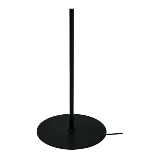
- Page 4 스탠드 베이스에 파이프를 조립하고, 파이프에 프레임을 조립합니다.
- Page 5 파이프 상단에 고정용 나사 홀에 나사(M3 x L5.5)를 체결하여 파이프와 프레임을 고정시킵니다. 16/22핀 케이블의 반대쪽 부분의 connector를 케이블과 일직선이 되도록 꺾어줍니다. 16/22핀 connector를 함께 튜브에 삽입합니다.
- Page 6 정리된 16/22핀 케이블과 HDMI 케이블을 삽입하여 통과시키고, 분리된 프레임을 재조립합니다. FRONT 라벨이 붙은 HDMI 케이블을 FRONT 면에 연결합니다. 붉은색 표시가 없는 16/22핀 케이블에 케이블 홀더를 끼우고 나사(M3 x L4.5)를 이용해 조립한 후 연결합니다. FRONT FRONT...
- Page 7 FRONT 라벨이 없는 HDMI 케이블을 REAR 면에 연결합니다. 붉은색 표시가 있는 16/22핀 케이블에 케이블 홀더를 끼우고 나사(M3 x L4.5)를 이용해 조립한 후 연결합니다. 나사 2개를 분리하여 LG 로고 방향을 변경하여 재조립합니다.
- Page 8 T-con 박스의 IR 수신부가 있는 면을 FRONT 면에 덮고, 반대쪽에서 나사(Φ3 x L6) 4개로 체결합니다 나머지 T-con 커버를 REAR 면에 덮고, 나사(Φ3 x L10) 2개로 체결합니다.
- Page 9 T-con 커버 하단에 나사(M4 x L8) 6개를 체결합니다. 사이니지 박스에 케이블을 연결합니다. FRONT 라벨이 붙은 HDMI 케이블은 위에, FRONT 라벨이 없는 HDMI 케이블은 아래에 체결합니다. 16/22핀 케이블의 경우 붉은색 표시가 있는 케이블을 위에 체결합니다.
- Page 10 16/22핀 케이블을 나사(M3 x L4.5) 2개로 각각 체결합니다. 잭커버의 홈을 케이블에 맞춰 덮고 나사(M3 x L4.5) 2개로 체결합니다.
- Page 11 사이니지 박스에 전원코드를 연결합니다.
- Page 12 모델 시리얼 번호...
- Page 13 OWNER’S MANUAL Stand kit Please read this manual carefully before operating your set and retain it for future reference. ACC-S-EH5C www.lg.com...
- Page 14 (M3 x L5.5)
- Page 15 Open the product box and remove the packaging materials and the T-con box in the order they appear. T-con box Loosen the six screws and remove the frame from the set.
- Page 16 Attach the pipe to the stand base and the frame to the pipe.
- Page 17 Attach the pipe to the frame by fastening a screw (M3 x L5.5) in the screw hole on the top of the pipe. Fold the connectors on the opposite side of the 16/22 pin cables to make them parallel to the cable. Insert the connectors of the 16/22 pin cables into the tubes.
- Page 18 Insert the arranged 16/22 pin cables and HDMI cables into the pipe, and then reassemble the frame. Connect the HDMI cable with the label marked ‘FRONT’ to the FRONT side. Insert the 16/22 pin cable without the red mark into the cable holder and attach it using a screw (M3 x L4.5). FRONT FRONT...
- Page 19 Connect the HDMI cable without the label marked ‘FRONT’ to the rear side. Insert the 16/22 pin cable with the red mark into the cable holder and attach it using a screw (M3 x L4.5). Remove the 2 screws, change the direction of the LG logo, and then reassemble.
- Page 20 Cover the FRONT side with the side of the T-con box cover that has the IR receiver and attach it using four screws (Φ3 x L6) on the opposite side. Cover the REAR side with the other T-con box cover and attach it using 2 screws (Φ3 x L10).
- Page 21 Fasten 6 screws (M4 x L8) to the bottom part of the T-con cover. Connect the cables to the Signage box. Here, the HDMI cable with the FRONT label is attached to the top, and the HDMI cable without the FRONT label is attached to the bottom. The 16/22 pin cable with the red mark must be connected to the upper part.
- Page 22 Attach the 16/22 pin cables using 2 screws (M3 x L4.5). Position the jack cover so the cables fit into the cut spaces and attach it using 2 screws (M3 x L4.5).
- Page 23 Connect the power cable to the Signage box.
- Page 24 MODEL SERIAL...