Quick Links

Related Manuals for Husqvarna BG 245


Summary of Contents for Husqvarna BG 245
- Page 1 BG 245, BG 375, BG 475 Operator's manual 2-28...
-
Page 2: Table Of Contents
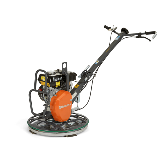
Transportation, storage and disposal......20 Operation................ 8 Technical data.............. 23 Maintenance..............12 EC Declaration of Conformity........28 Introduction Product overview (BG 245) 1. Throttle control 12. Muffler 2. Blade adjustment knob 13. Fuel tank cap 3. Clutch control 14. Fuel tank 4. - Page 3 2. Blade adjustment knob rotates, which prevents scratches on the wall. 3. Clutch control 4. Clutch holder The models BG 245 and BG 375 can be used with the optional accessory floating disc. 5. V-belt cover 6. Protection ring Intended use 7.
- Page 4 2. Product number 3. Product weight Fuel: Unleaded gasoline with a maximum of 4. Serial number 10% ethanol. 5. Manufacturer 6. Rated power 7. Production year Risk of injury. Be careful around the drive belt. Safety labels Hot surface. Keep your hands away from this area. XXXXXXXXXX Remove the floating disc before you lift the product.
- Page 5 • Make sure that you know how to stop the engine CAUTION: Used if there is a risk of damage quickly in an emergency. to the product, other materials or the • The operator must have the physical strength that is adjacent area if the instructions in the necessary to operate the product safely.
- Page 6 • Symptoms can occur during operation of the product • If it is possible, point the exhaust of the product or at other times. If you have symptoms and where it cannot cause dust to go into the air. continue to operate the product, the symptoms can Exhaust fumes safety increase or become permanent.
- Page 7 Note: The illustration shows the clutch control on • Use boots with steel toe-cap and non-slip sole. model BG 245 and BG 375 (H5-BC). The models • Use approved work clothing or equivalent close- BG 475 and BG 375 (H6-BC, H9-BC) have a longer fitting clothing that has long sleeves and long legs.
-
Page 8: Introduction
Operation Introduction To adjust the handle height • For BG 245: Loosen the lever, move the handle up or down to an applicable height and tighten the lever. WARNING: Read and understand the safety chapter before you use the product. - Page 9 3. Set the choke control in the correct position. To install the floating disc (BG 245, BG 375) a) If the engine is cold, close the choke. 1. Put the floating disc on a hard flat surface.
- Page 10 5. Hold the product handle with one hand and pull the a) For BG 245 and BG 375 (H5-BC): To decrease starter rope handle slowly until you feel resistance. the pressure on your hand, fold the clutch holder (A) on top of the clutch control.
- Page 11 4. Stop the product and remove it from the concrete • To turn to the right, push the handles down. surface. CAUTION: Do not let the product stay stationary on the concrete surface. This can cause marks and damages to the concrete surface.
-
Page 12: Maintenance
4. Move the fuel valve to the "OFF" position. b) BG 475, BG 375 (H6-BC, H9-BC): Maintenance Introduction For spare parts, speak to your Husqvarna dealer or service agent. WARNING: Read and understand the safety Maintenance schedule chapter before you do maintenance on the product. - Page 13 Maintenance Before use, After the Monthly, Yearly, each each 10 h first 20 h each 200 h 500 h Make sure that there are no fuel or oil leaks. Clean the product. Make sure that nuts and screws are tightened. Do a check of the fuel level and the engine oil level.
- Page 14 1. Put a container below the drain plug for the engine 2. Remove the paper filter element and the foam filter oil. element (A). 2. Remove the oil drain plug (A) and connect a hose (B). 3. Clean the air filter housing with a brush. 3.
- Page 15 Replace the V-belt if it is necessary. • Push grease through the grease nipples until grease comes out around the blade shafts. a) (BG 245): b) (BG 375): 4. Examine the tension of the V-belt. 5. If the tension is not sufficient, adjust the clutch wire (B).
- Page 16 2. Remove the outer ring. 2. Pull the blade shafts from the hub. 3. Replace damaged blade shafts. 4. Clean the contact surfaces on the blade shafts and the hub. 5. Lubricate the contact surfaces and install the blade 3. Pull the blade shafts from the hub. shafts.
- Page 17 To clean or replace the bearing for the 4. Remove the protection ring (A) and the needle bearing (B). pressure plate (BG 245) 1. Remove the screw and washer. 5. Clean the surfaces of all parts and lubricate 2. Remove the blade assembly. Use a puller if the carefully.
- Page 18 5. Lubricate the ball bearing with grease. Refer to Technical data on page 23 for correct type of grease. 6. Assemble in the opposite sequence. To replace the blades (BG 245) WARNING: Before you replace the blades, stop the product and let the engine become cool.
-
Page 19: Troubleshooting
1. Set the product in maintenance position. Refer to a) If the blade has wear on one edge only, turn the set the product in maintenance position on page 15 . blade 180 degrees and put it back. 2. Remove the screws. b) If the blade has wear on the front and rear edge, replace with a new blade. -
Page 20: Transportation, Storage And Disposal
For BG 245 and BG 375: a floating Let the concrete dry some more be- disc is used and the concrete is too fore you operate the product. - Page 21 To set the product in transport position To lift the product • For BG 245: Loosen the lever and fold the handle WARNING: Make sure that the lifting forward. equipment has the correct dimension. The type plate on the product shows the product weight.
- Page 22 Discard all chemicals, such as engine oil or fuel, at a service center or at an applicable disposal location. • When the product is no longer in use, send it to a Husqvarna dealer or discard it at a recycling location. 1071 - 001 - 11.12.2019...
- Page 23 Technical data Technical data BG 245 BG 375 H5- BC BG 375 H6-BC BG 375 H9-BC BG 475 Net weight, kg/lb 58/128 83/183 90.5/200 98/216 101/222.7 Operation weight, 60/132 87/192 93/205 102/225 105/231.5 EN500, kg/lb Engine brand, type Honda, GX 120...
- Page 24 Noise emissions BG 245 BG 375 H5- BG 375 H6-BC BG 375 H9-BC BG 475 Sound power level L meas- ured, dB(A) rel 1pW Sound pressure level L at the operators ear, dB(A) Vibration levels BG 245 BG 375 H5-...
- Page 25 Product dimensions, BG 245 Height with handle folded, Length including handle, 850/33.5 1449/57.0 mm/in. mm/in. Handle height, mm/in. 929/36.6 Handle width, mm/in. 631/24.8 Length with handle folded, Width of blade assembly, 799/31.5 610/24.0 mm/in. mm/in. 1071 - 001 - 11.12.2019...
- Page 26 Product dimensions, BG 375 (H5-BC) Height with handle folded, Handle height, mm/in. 1100/43.3 1060/41.7 mm/in. Length with handle folded, Handle width, mm/in. 1220/48 735/28.9 mm/in. Length including handle, Width of blade assembly, 1950/76.8 950/37.4 mm/in. mm/in. 1071 - 001 - 11.12.2019...
- Page 27 Product dimensions, BG 375 (H6-BC, H9-BC), BG 475 Handle width, mm/in. 700/27.6 Handle height, mm/in. 1300/51.2 Width of blade assembly, Length with handle folded, 950/37.4 1120/44.1 mm/in. mm/in. Height without handle, Height with handle folded, 795/31.3 1220/48 mm/in. mm/in. Length including handle, 2275/89.6 mm/in.
- Page 28 EC Declaration of Conformity EC Declaration of Conformity We, Husqvarna AB, SE-561 82 Huskvarna, Sweden, tel: +46-36-146500, declare on our sole responsibility that the product: Description Concrete Smoothing Machine, Trowel Brand Husqvarna Type/Model BG 245, BG 375, BG 475 Identification...
- Page 29 1071 - 001 - 11.12.2019...
- Page 30 1071 - 001 - 11.12.2019...
- Page 31 1071 - 001 - 11.12.2019...
- Page 32 www.husqvarnacp.com Original instructions 1140377-26 2019-12-19...