
Related Manuals for Huawei OptiX OSN 6800

Summary of Contents for Huawei OptiX OSN 6800
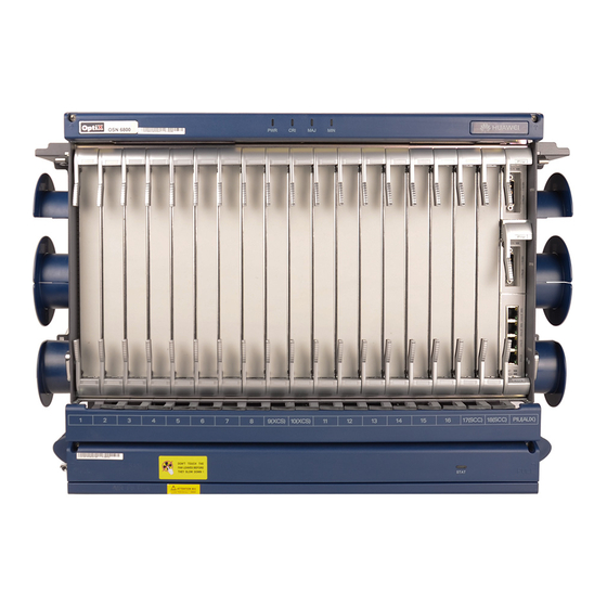
- Page 1 OptiX OSN 6800 Intelligent Optical Transport Platform Quick Installation Guide (N63B Cabinet) Issue: 16 Date: 2014-2-14 HUAWEI TECHNOLOGIES CO., LTD.
- Page 2 Notice The purchased products, services and features are stipulated by the contract made between Huawei and the customer. All or part of the products, services and features described in this document may not be within the purchase scope or the usage scope. Unless otherwise specified in the contract, all statements, information, and recommendations in this document are provided "AS IS"...
-
Page 3: Installation Flow
Installation Flow Start Before You Start Page 1 Precautions Page 4 Installing to 5 Subracks Regulation and Page 2 Precautions for Board Handling Installing Page 6 Boards Tools for Page 3 Setting Page 7 Installation Master/Slave to 10 Subracks Installing Page 4 Page Page... - Page 4 Precautions NOTE This document aims to provide simple and distinctive guidelines for hardware installation. This document does not describe operations for the pre-delivery installation. Instead, this document describers only the operations for on-site installation. CAUTION Safety Information When moving the cabinet, wear protective gloves to protect your hands.
- Page 5 Boards are fragile and valuable. When handling or placing a board, exercise caution and put it into a dedicated packing box. Coherent boards must be packed with original packaging materials during transportation. If the original packaging materials are lost, contact Huawei.
- Page 6 Tool for Installation Phillips screwdriver Measuring tape Flat-head screwdriver Marker Adjustable wrench Segmented blade utility knife Heat gun Socket wrench Cable cutter Wire stripper COAX crimping tool RJ45 crimping tool Diagonal pliers Coax stripper Network cable tester Power cable crimping tool Claw hammer Hammer drill Multimeter...
- Page 7 Installation Structural holes on one component column DCM frame 2, 3 Subrack 1 5, 6, 19, 20 OptiX OSN 6800 Subrack 4 Subrack 2 21, 22, 35, 36 Air deflector 37, 40 Subrack 3 46, 47, 60, 61 Cabinet column...
- Page 8 Install two CRPC boards and multiple DCM frames to the lower subrack. Front Installation Structural holes on one component column 2, 3 OptiX OSN 6800 DCM frame 4, 5 Subrack 3 6, 7 10, 12 CRPC 14, 16 Subrack 1...
-
Page 9: Installing Boards
48 V power connector is not detached. If an abnormality is found, contact Huawei engineers for help. 2. Handle boards gently to avoid damage to board connectors. - Page 10 3 Setting Master/Slave Subracks TN11AUX02 CAUTION Representing Representing Representing •Changing the subrack ID may interrupt services. •The J14, J17, and J18 jumpers must be set as specified in the figure. NOTE Representing Representing Representing •The J2, J3, J4, J15, J16 jumpers can be set to enable 32 states that represent decimal values 0-31.
- Page 11 3 Setting Master/Slave Subracks TN11AUX02 Subrack ID: 7 - 31...
- Page 12 3 Setting Master/Slave Subracks TN12AUX CAUTION Changing the subrack ID may interrupt services. NOTE •The TN12AUX board has two DIP switches. The value set by each switch can be 0 or 1 (in binary code). •ID1–ID4 correspond to pins 1–4 on SW2 and ID5–ID8 correspond to pins 1–4 on SW1. ID1–ID5 are valid and ID6– ID8 are reserved.
- Page 13 3 Setting Master/Slave Subracks TN12AUX Mapping between jumpers binary values and subrack IDs Subrack ID:1-15 Subrack Subrack Subrack (ID5) (ID1) (ID5) (ID5) (ID1) (ID1) (ID2) (ID2) (ID6) (ID2) (ID6) (ID6) (ID3) (ID7) (ID3) (ID7) (ID3) (ID7) (ID4) (ID4) (ID8) (ID8) (ID4) (ID8) (ID1)
- Page 14 4 Checking the Battery Jumper on the SCC TN11SCC CAUTION Make sure that the jumper settings are set as shown in the following figure prior to using an SCC board. When a battery is required, place a jumper cap over pin 3 and pin 2. When the power supplied by the battery is not required, place a jumper cap over pin 2 and pin 1.
- Page 15 4 Checking the Battery Jumper on the SCC CAUTION Make sure that the jumper settings are set as shown in the following figure prior to using an SCC board. When a battery is required, place a jumper cap over pin 3 and pin 2. When the power supplied by the battery is not required, place a jumper cap over pin 2 and pin 1.
- Page 16 5 Setting the Jumpers on the CRPC CRPC NOTE There are two groups of jumpers on the CRPC boards. The two groups are identified as J3 and J4. Jumpers 9 to 10 in J3 and 1 to 6 in J4 are used for internal identification on the board. To ensure the normal operation of the board, follow the requirements below to set the jumpers.
- Page 17 6 Setting the Jumpers on the ROP NOTE There are two groups of jumpers on the ROP boards. The two groups are identified as J3 and J4. Jumpers 9 to 10 in J3 and 1 to 6 in J4 are used for internal identification on the board. To ensure the normal operation of the board, follow the requirements below to set the jumpers.
-
Page 18: Installing Components
Installing Components 1 Installing the DCM Frame frame Mounting Screw NOTE Each DCM requires four screws. If only one DCM is required, install it to the left side of the DCM frame to facilitate distribution of optical fibers on the left. 2 Installing the CRPC/ROP Frame NOTE The CRPC frame is installed in the location ordinarily intended for the lower subrack. - Page 19 Installing and Routing Cables 1 Cable Holes at the Top and Bottom of the Cabinet Cable Holes at the Top of Cabinet NOTE Route optical fibers and cables into a cabinet through the cable holes at the top or bottom of the cabinet. Cable hole Cable hole Cable hole...
- Page 20 2 Cabinet Power Cable Connections (TN11PDU) Power Cable Connections to the Cabinet NOTE Power cable connections vary depending on the power sources in the equipment room. When the power source supplies one input of 63 A, TN11PDU is used to interface four main/backup power inputs. A-RTN2(+) B-RTN1(+) A-RTN1(+)
- Page 21 Installing the Junction Box Flat-head screwdriver Power Cable Connections to the Cabinet – (With the Junction Box) B-RTN(+) A-RTN(+) A-NEG(-) B-NEG(-) Cabinet power cables -48 V -48 V Ground cables Power source in the Power source in the equipment room equipment room Subrack 4 Adjustable wrench...
- Page 22 2 Cabinet Power Cable Connections (DPD63-4-8 PDU) DPD63-4-8 PDU DANGER Do not install any copper fitting in the power output areas of the DC PDU. If copper fittings are required, install them only in the power input areas of the DC PDU. NOTE Remove the front panel of the DC PDU prior to installing power cables.
- Page 23 2 Cabinet Power Cable Connections (DPD63-4-8 PDU) DPD63-4-8 PDU RTN(+) terminal blocks and copper fittings for the middle area of the DC PDU CAUTION 1. There are two types of RTN(+) terminal blocks for the PDU and correspond to two types of copper fittings. 2.
- Page 24 2 Cabinet Power Cable Connections (DPD63-4-8 PDU) Power Cable Connections to the Cabinet NOTE Power cable connections vary depending on the power sources in the equipment room. When the power source supplies one input of 63 A, DPD63-4-8 PDU is used to interface four main/backup power inputs. A-RTN2(+) B-RTN1(+) A-RTN1(+)
- Page 25 2 Cabinet Power Cable Connections (DPD63-4-8 PDU) Replacing Pre-installed Copper Fittings DANGER Do not install any copper fitting in the power output areas of the DC PDU. If copper fittings are required, install them only in the power input areas of the DC PDU. NOTE By default two-in-one copper fittings have been installed on NEG(-) and RTN(+) Two-in-one...
- Page 26 3 Installing and Routing Cabinet Ground and Power Cables(TN11PDU) Overhead Cabling CAUTION Do not install or remove power cables while the equipment is powered on. Ensure that the power is switched off prior to removing or installing a power cable to avoid bodily injuries. NOTE Install ground cables first and then power cables to a cabinet.
- Page 27 Underfloor Cabling Mode CAUTION Do not install or remove power cables while the equipment is powered on. Ensure that the power is switched off prior to removing or installing a power cable to avoid bodily injuries. Adjustable wrench Phillips screwdriver Ground cable (yellow-green) -48 V Power...
- Page 28 3 Installing and Routing Ground and Power Cables to the Cabinet (DPD63-4- 8 PDU) Overhead Cabling CAUTION Do not install or remove power cables while the equipment is powered on. Ensure that the power is switched off prior to removing or installing a power cable to avoid bodily injuries. Adjustable wrench Phillips screwdriver NOTE...
- Page 29 Underfloor Cabling CAUTION Do not install or remove power cables while the equipment is powered on. Ensure that the power is switched off prior to removing or installing a power cable to avoid bodily injuries. Ground cable M8 screw NOTE (yellow-green) When power and ground cables are installed underfloor, there is little space left for routing external fibers.
- Page 30 4 Installing and Routing Ground and Power Cables to a Subrack Installing Ground Cables Phillips screwdriver Ground cable Ground point for the DPD63-4-8 PDU Connect one end of the ground cable of each subrack to the bottom-side ground bolt of the subrack and the other end to an idle ground bolt adjacent to this subrack on the right-side column of the cabinet and use a screw to secure this end.
- Page 31 Cabinet and Subrack Power Cable Connections (TN11PDU) Subrack power Subrack power RTN2(+) NEG1(-) output terminals output terminals RTN1(+) NEG2(-) PGND of cabinet SW2A SW4A SW2B SW4B power terminal SW3A SW5A SW3B SW5B NOTE The TN11PIU02 board supports –48 V and –60 V DC power options. The TN11PIU03 boards supports only –48 V DC power options.
- Page 32 Cabinet and Subrack Power Cable Connections (DPD63-4-8 PDU) The following table provides the mapping between power switch numbers on the PDU and subracks. Power Switch No. Subrack No. SW2A, SW2B SW3A, SW3B SW4A, SW4B SW5A, SW5B SW2A SW4A SW2B SW4B SW1A SW3A SW1B...
- Page 33 Installing and Routing Power Cables WARNING Do not install or remove power cables while the equipment is powered on. Ensure that the power is switched off prior to removing or installing a power cable to avoid bodily injuries. Cable tie Diagonal pliers Phillips screwdriver Route power cables...
- Page 34 5 Installing and Routing Network Management Cables Scenarios with Only One NE in Master/Slave Mode(Tree-Like Connections) Network cable STAT STAT PROG PROG NM_ETH1 NM_ETH2 STAT STAT PROG PROG ETH1 ETH2 STAT PROG STAT STAT PROG PROG CAUTION NMS computer Connect RJ-45 cables according to the picture and do not connect RJ-45 cables to the LAMP...
- Page 35 5 Installing and Routing Network Management Cables Scenarios with Multiple NEs in Master/Slave Mode (Tree-Like Connections) Network cable STAT STAT PROG PROG NM_ETH1 STAT STAT PROG PROG NM_ETH2 ETH1 ETH2 STAT PROG STAT STAT PROG PROG CAUTION NMS computer Connect RJ-45 cables according to the picture and do not connect RJ-45 cables to the LAMP...
- Page 36 Non Master/Slave Mode Network cable STAT STAT PROG PROG NM_ETH1 NMS computer NM_ETH2 STAT STAT ETH1 PROG PROG ETH2 STAT PROG CAUTION STAT STAT PROG PROG Connect RJ-45 cables according to the picture and do not connect RJ-45 cables to the LAMP interfaces.
- Page 37 6 Installing and Routing Alarm and Indicator Cables Installing and Routing External Alarm Cables To centralized alarm system ALMO2 SERIAL ALMO1 Subrack 8 Subrack 4 ALMO2 SERIAL ALMO1 ALMO2 SERIAL Subrack 3 Subrack 7 ALMO1 ALMO2 ALMI1 ALMI2 SERIAL ALMO1 ALMO2 SERIAL Subrack 6...
- Page 38 Use the clock cascading cables to connect clock interfaces between NEs and use the straight through cables to connect time interfaces. For the cables used to connect the OptiX OSN 6800 to other equipment, see Clock/Time Cable in the Hardware Description.
- Page 39 Installing and Routing Clock Cables Installing and Routing Clock Cables NOTE The shielded cables without protection boot are used for transmitting clock signals. Do not use the CLK port and the IN/OUT port at the same time. Clock signal output Slave subrack Slave subrack Slave subrack...
- Page 40 8 Installing and Routing Cables to the CRPC/ROP SW1A SW6A SW1B CRPC/ROP SW6B power cables Tributary power output terminals Power cable of CRPC frame Subrack 3 ETH3 ALM01 ALM02 ALM03ALM04 Subrack 2 Subrack 1 STAT PROG Communication cable between the LINE CRPC 2 CRPC board and subrack...
- Page 41 Installing and Routing Fibers 1 Open Corrugated Pipe NOTE The open corrugated pipe cannot be loaded with too many optical Internal pipe fibers. A maximum of 60 fibers with 2 mm diameter are recommended for an open corrugated pipe with 32 mm diameter.
- Page 42 External Fibers in Underfloor Cabling Mode NOTE Choose a coiling fiber spool according to the length of redundant fibers. Wind the fibers around the big spool first and then the smaller spool. The fibers should not be coiled too tightly or too loosely. Ensure that the bending radius of fibers is not less than 30 After the fiber installation, insert fiber plugs in idle interfaces and cover idle fibers with fiber caps.
- Page 43 4 Installing and Routing Fibers to a DCM Frame NOTE Fiber holder When you connect fibers to DCMs, make sure that the DCMs and fibers are correctly connected in the two directions based on the engineering documents specific to the site. Cable clip Fiber 5 Installing and Routing Fibers Between Subracks...
- Page 44 Installing the Orderwire Phone STAT PROG CLASS 1 LASER PRODUCT STAT PROG CLASS 1 LASER PRODUCT Orderwire Base Airduct frame phone Secure the mount set of the orderwire telephone on the air deflector by using a double faced adhesive tape. Plug one end of the telephone wire into the EOW port on the SC1 or SC2 board in the subrack.
- Page 45 Installing the Digital Video O/E Conversion Chassis Appearance of the Digital Video O/E Conversion Chassis Front Rear Electrical port Other ports Optical port Appearance of the Power Supply Unit and Power Cable Connections Areas A and B each provide six power inputs for mutual backup. In areas A and B, select a total of two power inputs (working and protection) that are identified with the same number to provide power to the O/E conversion chassis.
-
Page 46: Checking The Installation
Checking the Installation 1 Installation Checklist Double check that these items have been properly performed. What to Check For Method The cabinet is positioned in the proper place as prescribed by the engineering Visual inspection design. The cabinet components must be installed correctly, without damaged or loosen Visual inspection parts. - Page 47 Subrack Name of a Single Subrack Breaker not the required, do not connect the power. OptiX OSN 6800 1350 W 32 A Test the voltage between NEG(-) and RTN(+) on the DC PDU. Power supply is -48 V Power supply is -60 V Voltage range -40 V to -57.6 V...
- Page 48 Setting Up Optical Paths Station A Station B East West Fiber jumper Optical power meter Measure the optical power at the OUT port on the FIU board at the transmit end and record the reading as Measure the output optical power of the ODF at the transmit end and record the reading as Measure the input optical power of the ODF at the receive end and record the reading as Measure the input optical power at the IN port on the FIU board at the receive end and record the reading as...
-
Page 49: Engineering Labels
Engineering Labels 1 Attaching Labels NOTE Attach a label to a cable, 2 cm away from the connector. Attaching a Label to a Power Cable Attach the identification plate on Identification plate the right side of the cable when the cable is routed vertically. B03 --- -48V2 Cable Identification plate... - Page 50 2 Standard Engineering Labels Name Content Example Remarks MN (BC): BC is written right under MN. On the loaded open -48V2 -48V2 rack side: MN identifies the row and column number of the power distribution facilities such as the MN(BC) - -48V1 control open rack and power MN(BC) - -48V2 Labels for...
- Page 51 HUAWEI TECHNOLOGIES CO., LTD. Huawei Industrial Base Bantian Longgang Shenzhen 518129 People’s Republic of China www.huawei.com...