
Related Manuals for GE Multilin G500


Summary of Contents for GE Multilin G500
- Page 1 Grid Solutions Multilin G500 Substation Gateway Instruction Manual 994-0152 Version 1.00 Revision 1 GE Information...
- Page 2 GE Grid Solutions Copyright Notice © 2019, General Electric Company. All rights reserved. The information contained in this online publication is the exclusive property of General Electric Company, except as otherwise indicated. You may view, copy and print documents and graphics incorporated in this online publication (the “Documents”) subject to the following: (1) the Documents may be used solely for personal, infor-...
-
Page 3: Table Of Contents
G500 Substation Gateway Table of contents PRODUCT SUPPORT Access the GE Grid Solutions web site................7 Search GE Grid Solutions technical support library..........7 Contact GE Grid Solutions technical support ............7 GE Grid Solutions address ....................8 Product returns.......................8 ABOUT THIS Purpose ..........................9 DOCUMENT Intended audience ......................9... - Page 4 IRIG-B output..............................68 CPU ..................................69 TEMP..................................69 SSD..................................69 STATUS ................................70 Power...................................70 OLED Display ..............................70 Rear indicators......................71 6. SPECIFICATIONS Product specifications ....................73 Environmental specifications..................74 Temperature and Humidity........................74 Altitude................................75 Ingress Protection (IEC 60529) .........................75 Liquid Protection ............................75 GE INFORMATION G500 SUBSTATION GATEWAY INSTRUCTION MANUAL...
- Page 5 G500 FROM SERVICE Removing configuration data on a PC..............82 A. STANDARDS & Compliance Standards ....................83 COMPLIANCE B. CUL C. WARRANTY Warranty........................87 D. LIST OF Acronym Definitions ....................89 ACRONYMS REVISION HISTORY Revision history ......................91 G500 SUBSTATION GATEWAY INSTRUCTION MANUAL GE INFORMATION...
- Page 6 TABLE OF CONTENTS GE INFORMATION G500 SUBSTATION GATEWAY INSTRUCTION MANUAL...
-
Page 7: Product Support
Contact GE Grid Solutions technical support GE Grid Solution Technical Support is open 24 hours a day, seven days a week for you to talk directly to a GE representative. In the U.S. and Canada, call toll-free: 1 800-547-8629... -
Page 8: Ge Grid Solutions Address
You are sent the RMA number and RMA documents via fax or e-mail. Once you receive the RMA documents, attach them to the outside of the shipping package and ship to GE. Product returns are not accepted unless accompanied by the Return Merchandise Authorization number. -
Page 9: About This Document
G500 Online Help • Module layouts, as available • The G500 Substation Gateway Software Configuration Guide (GE part number SWM0101). For the current version of the G500 Instruction Manual, please download a copy from: http://www.gegridsolutions.com/app/ViewFiles.aspx?prod=G500&type=3 G500 SUBSTATION GATEWAY INSTRUCTION MANUAL... -
Page 10: How To Use This Guide
Indicates a hazardous situation which, if not avoided, could result in death or serious injury. Indicates a hazardous situation which, if not avoided, could result in minor or moderate injury. Indicates practices that are not related to personal injury. GE INFORMATION G500 SUBSTATION GATEWAY INSTRUCTION MANUAL... -
Page 11: Introduction
• The successful operation of this equipment depends upon proper handling, installation, and operation. Neglecting fundamental installation requirements may lead to personal injury as well as damage to electrical equipment or other property. G500 SUBSTATION GATEWAY INSTRUCTION MANUAL GE INFORMATION... -
Page 12: Warning Symbols
If the G500 is used in a manner not specified in this manual, the protection provided by the equipment may be impaired. • Changes or modifications made to the unit not authorized by GE could void the warranty. Warning symbols Table 1 explains the meaning of warning symbols that may appear on the G500 or in this manual. - Page 13 Serial: 8 factory installed ports, expandable up to 20 ports, RS-232 and RS-485 are accessible via individual RJ45 connectors. • Ethernet: Six Ethernet interfaces available through SFP cages. Each cage supports: 100/1000BaseT, 100BaseFX or 1000BaseSX. Figure 1: G500 G500 SUBSTATION GATEWAY INSTRUCTION MANUAL GE INFORMATION...
-
Page 14: Order Code
* Storage option A is only available with CPU option A and storage option B is only available with CPU option B. ** Visit the online store for application licenses ordering codes. For latest configuration and options, please visit the online store: http://www.gegridsolutions.com/app/ViewFiles.aspx?prod=G500&type=3. GE INFORMATION G500 SUBSTATION GATEWAY INSTRUCTION MANUAL... -
Page 15: Mcp Spares And Accessories
UART Card options MCP PCIe UART CARD, 4x PORT (RJ45) RS232/485 [528- These options are only 1001LF] MCP BUILT-IN UART CARD, 4x PORT (RJ45) RS232/485 available when Spare [528-1003LF] type is UART Card G500 SUBSTATION GATEWAY INSTRUCTION MANUAL GE INFORMATION... - Page 16 CHAPTER 1: INTRODUCTION GE INFORMATION G500 SUBSTATION GATEWAY INSTRUCTION MANUAL...
-
Page 17: Unpacking And Inspection
“zap” the board without you knowing it; a small discharge, imperceptible to the eye and touch, can often be enough to damage electronic components. Extra caution should be taken in cold and dry weather when electrostatic charge easily builds up. G500 SUBSTATION GATEWAY INSTRUCTION MANUAL GE INFORMATION... -
Page 18: Unpacking
If damage is observed (usually in the form of bent component leads or loose socketed components), contact GE Technical Support for additional instructions. Depending on the severity of the damage, it may be necessary to return the product to the factory for repair. -
Page 19: Installing The G500
The G500 is mounted in 3U slot of a 19” rack by use of 6 screws compliant to IEC60297-3 with STD hole Pattern. Screws Use screws with a shaft diameter close to 5mm. For example, M5 or UNF 10-32 screws. G500 SUBSTATION GATEWAY INSTRUCTION MANUAL GE INFORMATION... - Page 20 For screw torque specification, refer to “General Torque Values for Screws” on page 79. Install 2 of the screws at the same height in the 19” rack. The screws should be screwed in to a distance of about 3 mm between screw head and rack. GE INFORMATION G500 SUBSTATION GATEWAY INSTRUCTION MANUAL...
- Page 21 The recommended tool torque settings for zinc-plated mounting screws are: – 10-32 UNF screws use 22.2 in-lb [2.50 Nm] – 12-24 UNC screws use 31.0 in-lb [3.51 Nm] – M5x0.45 screws use 18.1 in-lb [2.04 Nm] G500 SUBSTATION GATEWAY INSTRUCTION MANUAL GE INFORMATION...
- Page 22 The minimum specified spacing to the front and behind the G500 is 5cm (2”). Other spacing requirements are indicated in the following diagram. These requirements are met when the G500 is installed using the provided rack mounting kit. GE INFORMATION G500 SUBSTATION GATEWAY INSTRUCTION MANUAL...
-
Page 23: General Advice
The grounding wire should be AWG 12 or lower and not longer than 1 meter. Power input The mating connector is the 5-pin “Phoenix 1942293”. This connector type is required for IP30 compliance. connector G500 SUBSTATION GATEWAY INSTRUCTION MANUAL GE INFORMATION... -
Page 24: Power Supply Unit (Psu)
The DC input voltage is 100 to 300V. The PSU tolerates a +10%/-12% variation in these values (88 to 330V). With DC input, the PSU has a maximum current consumption of 1.8A. When using AC power, connect the “~”, “N“and “GND” wires according to the following figure. GE INFORMATION G500 SUBSTATION GATEWAY INSTRUCTION MANUAL... - Page 25 The fuse is placed in “N”/ ”-“ connection of the power supply. The fuse is soldered directly onto the product. There is no fuse holder. The fuse should only be replaced by GE personnel. Overvoltage The voltage to the inner loads is protected by a varistor. High increase of the voltage will protection cause the internal current fuse to blow and/or the Varistor to break.
-
Page 26: Low Voltage Power Supply
CHAPTER 3: INSTALLING THE G500 The varistor is soldered directly on the product. There is no fuse holder. The varistor should only be replaced by GE personnel. Low Voltage Power Supply The Low Voltage Power Supply only handles DC input, with DC input voltage from 20 to 54V. -
Page 27: Power-On Self-Test (Post)
If the G500 does not pass one or more of the above tests, the board will fail the POST and display a hexadecimal value on the lower right corner of the screen. Please contact GE’s Grid Solution support with the hexadecimal code in this case. -
Page 28: Fail Over Sequence
The RS232 switch panel transfers all serial field connections to the standby G500, which then becomes the active G500. Required components To implement a redundant G500 system, you need the following components Component Function GE part number RS232 Switch Panel Communications switch. 517-0247 Power Supply Power supply to power the RS232 switch panel. - Page 29 Figure 2 on page 32. Connect TB4 pins 1 (SET) and 2 (RESET) on the master RS232 switch panel to TB2 pins 1 and 2 on the slave RS232 switch panel using the cable specified (GE part number 970- 0161) or similar.
-
Page 30: Rs232 Switch Panel
When connecting to more than 8 field devices, you must double the number of RS232 switch panels used. When using this configuration, follow the instructions in “To set up a redundant system with two RS232 switch panels:” on page 29. GE INFORMATION G500 SUBSTATION GATEWAY INSTRUCTION MANUAL... - Page 31 CHAPTER 3: INSTALLING THE G500 Figure 1: Redundancy Wiring - Single RS232 Switch Panel G500 SUBSTATION GATEWAY INSTRUCTION MANUAL GE INFORMATION...
- Page 32 CHAPTER 3: INSTALLING THE G500 Figure 2: Redundancy Wiring - Dual RS232 Switch Panel (1 of 2) GE INFORMATION G500 SUBSTATION GATEWAY INSTRUCTION MANUAL...
- Page 33 CHAPTER 3: INSTALLING THE G500 Figure 3: Redundancy Wiring - Dual RS232 Switch Panel (2 of 2) G500 SUBSTATION GATEWAY INSTRUCTION MANUAL GE INFORMATION...
- Page 34 CHAPTER 3: INSTALLING THE G500 Figure 4: Redundancy Wiring - Redundant RS232 Switch Panel (1 of 2) GE INFORMATION G500 SUBSTATION GATEWAY INSTRUCTION MANUAL...
- Page 35 CHAPTER 3: INSTALLING THE G500 Figure 5: Redundancy Wiring - Redundant RS232 Switch Panel (2 of 2) G500 SUBSTATION GATEWAY INSTRUCTION MANUAL GE INFORMATION...
- Page 36 CHAPTER 3: INSTALLING THE G500 GE INFORMATION G500 SUBSTATION GATEWAY INSTRUCTION MANUAL...
-
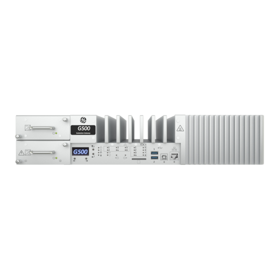
Page 37: Interfaces
G500 Substation Gateway. First look at the G500 Front panel The front panel of the G500 provides easy access to the status indicators, user connections and power supply units. Figure 1: G500 front panel G500 SUBSTATION GATEWAY INSTRUCTION MANUAL GE INFORMATION... -
Page 38: Rear Panel
The communication cards are powered from the G500. The types of communication cards included in your G500 depend on what was ordered for your substation application. GE INFORMATION G500 SUBSTATION GATEWAY INSTRUCTION MANUAL... -
Page 39: External Interfaces
DASH: • SOL port • Remote USB • Remote power control • Remote board info The port uses an RTL8111EP network. Drivers are freely available for several operating systems on the Realtek website. G500 SUBSTATION GATEWAY INSTRUCTION MANUAL GE INFORMATION... -
Page 40: Reset Button
The cumulative current draw of both ports is limited to 1A due to thermal and power budget restrictions. The maximum cable length for USB 3.0 cables is 3m (=118in). Using longer cables than specified for each port might result in data loss. GE INFORMATION G500 SUBSTATION GATEWAY INSTRUCTION MANUAL... -
Page 41: Sd Card
Each display port is capable of supporting two suitable displays via Multi Stream Transport (MST). G500 SUBSTATION GATEWAY INSTRUCTION MANUAL GE INFORMATION... -
Page 42: Alarm
48VAC or 75VDC with maximum 100mA to comply with IEC 61850-3. If 61850-3 Compliance is not required, the relay may switch up to 300VAC or 300VDC. This Port is isolated from the rest of system in accordance to IEC60950 for use with mains. GE INFORMATION G500 SUBSTATION GATEWAY INSTRUCTION MANUAL... -
Page 43: Irig - In
There is a IRIG-B output connector available at the rear of the unit. This output can be used to synchronize external equipment or other units to this unit. The supported IRIG-B formats are 002 and 006. The supported levels are compliant to TTL by a load of 25Ohm or higher. G500 SUBSTATION GATEWAY INSTRUCTION MANUAL GE INFORMATION... -
Page 44: Serial Ports
13 through 16 Expansion Slot 2 1 through 4 17 through 20 Expansion Slot 3 1 through 4 The serial ports support 4 communication modes • RS232 • RS422 • RS485 4-Wire • RS485 2-Wire GE INFORMATION G500 SUBSTATION GATEWAY INSTRUCTION MANUAL... - Page 45 RS-232 and RS-485 connections must comply with the following requirements: • Cables must be shielded • D-type connector covers must provide EMC shielding (e.g. metalized plastic or die cast metal covers). G500 SUBSTATION GATEWAY INSTRUCTION MANUAL GE INFORMATION...
- Page 46 Power down system gracefully. Disconnect all hazardous live circuits and sources of electrical power. Remove both power supplies. Remove screws and push lid to the rear until markings on lid and chassis align. GE INFORMATION G500 SUBSTATION GATEWAY INSTRUCTION MANUAL...
- Page 47 CHAPTER 4: INTERFACES Pull lid to outside until second marking aligns. Lift lid to remove. G500 SUBSTATION GATEWAY INSTRUCTION MANUAL GE INFORMATION...
- Page 48 CHAPTER 4: INTERFACES Remove attachment screws. Pull UART package out of slots (be careful, do not to damage ESD gasket at the rear). GE INFORMATION G500 SUBSTATION GATEWAY INSTRUCTION MANUAL...
- Page 49 CHAPTER 4: INTERFACES Exchange the UART module. 10. Check that the thermal connector pads on the PCB are still in place. If the thermal pads are damaged or missing, contact GE for replacements. G500 SUBSTATION GATEWAY INSTRUCTION MANUAL GE INFORMATION...
- Page 50 11. Insert the UART module into slots and attach the UART module by re-installing the screws from the power supply bay. Be careful, do not damage the EMI gasket on the rear of the unit. Otherwise, since damage may result in reduced ESD protection. GE INFORMATION G500 SUBSTATION GATEWAY INSTRUCTION MANUAL...
- Page 51 CHAPTER 4: INTERFACES 12. Attach the lid a little to the rear and out of position (In the right position both lid and chassis markings align). G500 SUBSTATION GATEWAY INSTRUCTION MANUAL GE INFORMATION...
- Page 52 CHAPTER 4: INTERFACES 13. Push the lid inwards. 14. Push the lid to the front and attach all screws. For screw torque specification, refer to “General Torque Values for Screws” on page 79. GE INFORMATION G500 SUBSTATION GATEWAY INSTRUCTION MANUAL...
-
Page 53: Ethernet Ports
Media Designation Cable Connector Twisted Pair Ethernet 100/1000Base-T UTP (Unshielded Twisted Pair) – CAT 5 RJ45 or better Fiber optic 100BASE-FX Fiber optic cable multimode Fiber optic 1000BASE-SX Fiber optic cable multimode G500 SUBSTATION GATEWAY INSTRUCTION MANUAL GE INFORMATION... -
Page 54: Internal Interfaces
The ALARM connector and the both power supply connectors have to be disconnected before housing is opened! Opening cover To change or add the cards open the chassis by performing following steps: Undo the PCIe heat sink screws if tightened. GE INFORMATION G500 SUBSTATION GATEWAY INSTRUCTION MANUAL... - Page 55 CHAPTER 4: INTERFACES Remove the screws and push the cover to the rear until markings on the lid and chassis align. G500 SUBSTATION GATEWAY INSTRUCTION MANUAL GE INFORMATION...
- Page 56 CHAPTER 4: INTERFACES Pull the cover outwards until the second markings on the lid and chassis align. Lift the lid to remove. GE INFORMATION G500 SUBSTATION GATEWAY INSTRUCTION MANUAL...
-
Page 57: Closing Cover
This Unit is to be serviced by trained personnel only. Closing cover Attach the lid a little to the rear and out of position (In the right Position both lid and chassis markings align). G500 SUBSTATION GATEWAY INSTRUCTION MANUAL GE INFORMATION... - Page 58 CHAPTER 4: INTERFACES Then push lid inwards. Push the lid to the front and attach all screws. For screw torque specification, refer to “General Torque Values for Screws” on page 79. GE INFORMATION G500 SUBSTATION GATEWAY INSTRUCTION MANUAL...
-
Page 59: M.2 Ssd
Open the cover by following the steps from “Opening cover” on page 54: device Loosen the M.2 heat sink screws, pull heat sink up until the keyholes allow removal of the heat sink. Unscrew the M.2 module and remove the module. G500 SUBSTATION GATEWAY INSTRUCTION MANUAL GE INFORMATION... - Page 60 Attach the piggyback gap pads on the top of the new module. Use an M2.5 screw to fasten the M.2 module in the empty G500 slot. Align the heat sink keyholes with the screws and push the heat sink keyholes over the screws. GE INFORMATION G500 SUBSTATION GATEWAY INSTRUCTION MANUAL...
-
Page 61: Pcie Slots
Order code section on page 14. The G500 supports up to three PCIe cards. Only PCIe cards supplied with the G500 or ordered from GE should be used. Use of non-G500 PCIe cards can result in unexpected behavior and may cause permanent damage to the equipment. - Page 62 Closing cover on page 57. After closing the G500 cover, tighten all heat contact screws that now correspond to occupied PCIe slots. For screw torque specification, refer to “General Torque Values for Screws” on page 79. GE INFORMATION G500 SUBSTATION GATEWAY INSTRUCTION MANUAL...
-
Page 63: Usb 2 Dongle Slot
For the mounting position of a USB dongle (maximum dimensions: 53mmx22mmx13mm) dongle see the figure below. In order to withstand standard shock and vibration levels the dongle must be tie-wrapped to the pre-installed mounting structure as shown above. G500 SUBSTATION GATEWAY INSTRUCTION MANUAL GE INFORMATION... - Page 64 CHAPTER 4: INTERFACES GE INFORMATION G500 SUBSTATION GATEWAY INSTRUCTION MANUAL...
-
Page 65: Indicators
G500 Substation Gateway Chapter 5: Indicators Indicators The G500 includes LED indicators for communication interfaces as well as additional indicators for different operational states. Front Indicators G500 SUBSTATION GATEWAY INSTRUCTION MANUAL GE INFORMATION... -
Page 66: Ethernet
Ethernet Port (SFP) LEDs There are six LEDs located on the front of the unit indicate the status of the corresponding rear SFP links: STATUS INDICATIOR No Link 100 MBit no activity Orange GE INFORMATION G500 SUBSTATION GATEWAY INSTRUCTION MANUAL... -
Page 67: Serial Port Leds
Serial Port LEDs Up to 8 numbered LEDs located on the front of the unit indicate the status of the corresponding rear UART ports: STATUS INDICATIOR No traffic Transmitting Green Receiving Transmitting and receiving Orange G500 SUBSTATION GATEWAY INSTRUCTION MANUAL GE INFORMATION... -
Page 68: Irig-B Input
IRIG-B input watchdog signal IRIG-B output The IRIG-B output option is not available in the G500 v1.00 release. STATUS INDICATIOR IRIG-B output is present and the internal Green clock is synch’ed from an external source GE INFORMATION G500 SUBSTATION GATEWAY INSTRUCTION MANUAL... -
Page 69: Cpu
All power rails OK, CPU running Green All power rails OK, CPU standby/off Orange One or more power rails has failed TEMP STATUS INDICATIOR No thermal alert Application controlled (temperature warning) Orange Critical temperature Green light indicates activity G500 SUBSTATION GATEWAY INSTRUCTION MANUAL GE INFORMATION... -
Page 70: Status
The G500 provides a monochrome/white OLED display. The OLED display will show the model number “G500” when any button is pressed for five minutes and then will turn off. The OLED display incorporates four buttons which are not supported in the G500 v1.00 release. GE INFORMATION G500 SUBSTATION GATEWAY INSTRUCTION MANUAL... -
Page 71: Rear Indicators
CHAPTER 5: INDICATORS Rear indicators If PCIe cards are installed which support indicator lights, the lights are visible through the holes at the rear of the G500 unit. G500 SUBSTATION GATEWAY INSTRUCTION MANUAL GE INFORMATION... - Page 72 CHAPTER 5: INDICATORS GE INFORMATION G500 SUBSTATION GATEWAY INSTRUCTION MANUAL...
-
Page 73: Specifications
All software selection persist when power cycled. IRIG-B available on all serial interfaces. +12V output available on 2x serial interfaces Port 4 and Port 8. It is limited to 0.5A (6W) with short circuit protection and auto recovery. G500 SUBSTATION GATEWAY INSTRUCTION MANUAL GE INFORMATION... -
Page 74: Environmental Specifications
* if PCIe Cards are installed the operating temperature of the system is reduced to 60°C. If non-compliant PCIe Cards are used the user has to take care of proper operation of the plug-in card and the operating temperature of the System may be decreased. GE INFORMATION G500 SUBSTATION GATEWAY INSTRUCTION MANUAL... -
Page 75: Altitude
The G500 is designed to protect the internal electronics from small amounts of liquid falling vertically or which may accumulate on the top surface of the chassis. Mean Time Between Failure Part GE Part Failure In MTBF in hours Number Time (FIT) @40°C... -
Page 76: Mechanical Specifications
Mechanical Specifications Weight Part Weight in kg G500, 0 serial ports, without PSU G500, 4 serial ports G500, 8 serial ports Mounting bracket HV PSU LV PSU Dimensions All dimensions in mm [inch] GE INFORMATION G500 SUBSTATION GATEWAY INSTRUCTION MANUAL... - Page 77 CHAPTER 6: SPECIFICATIONS G500 SUBSTATION GATEWAY INSTRUCTION MANUAL GE INFORMATION...
- Page 78 CHAPTER 6: SPECIFICATIONS GE INFORMATION G500 SUBSTATION GATEWAY INSTRUCTION MANUAL...
-
Page 79: General Torque Values For Screws
Exposure to excessive temperature or other extreme environmental conditions might cause damage and/or unreliable operation. To avoid deterioration and early failure of electrolytic capacitors, power up units that are stored in a de-energized state once every 12 months, for one hour continuously. G500 SUBSTATION GATEWAY INSTRUCTION MANUAL GE INFORMATION... - Page 80 CHAPTER 6: SPECIFICATIONS GE INFORMATION G500 SUBSTATION GATEWAY INSTRUCTION MANUAL...
-
Page 81: Removing The G500 From Service
For an RMA: Remove the Solid State Drive (SSD) from the G500 using the reverse of the SSD installation procedure found earlier in this manual; send the G500 unit to GE and safekeep the drive. If the drive is faulty, GE recommends destroying the old drive as per NIST* recommendations. - Page 82 Recommended: Physically removing and destroying the data storage media, or • Using a program to securely wipe (that is, completely erase) the data storage media (that is, not just reformat or remove the names of the files from the file allocation table). GE INFORMATION G500 SUBSTATION GATEWAY INSTRUCTION MANUAL...
- Page 83 IEC 60529 IP30 Environmental (Cold) IEC 60068-2-1 -40°C 16 hrs. (Storage and Operational) Environmental (Dry heat) IEC 60068-2-2 60°C 16hrs for Quad Core 70°C 16 hrs. Dual Core 85°C 16 hrs. Storage (both models) G500 SUBSTATION GATEWAY INSTRUCTION MANUAL GE INFORMATION...
- Page 84 Devices Installed in Electric Power Substations Communication Networks and IEC 61850-3:2013 Per Standard systems for power Utility Automation-Part 3 SAFETY EN/IEC 60950-1: 2005 Per standard UL marking UL60950-1 2 Ed /CSA NWGQ2 & NWGQ8 C22.2 60950-1-07 GE INFORMATION G500 SUBSTATION GATEWAY INSTRUCTION MANUAL...
- Page 85 G500 Substation Gateway Appendix B: cUL G500 SUBSTATION GATEWAY INSTRUCTION MANUAL GE INFORMATION...
- Page 86 APPENDIX B: CUL GE INFORMATION G500 SUBSTATION GATEWAY INSTRUCTION MANUAL...
- Page 87 Appendix C: Warranty Warranty Warranty For products shipped as of October 1st, 2013, G500 warrants most of its GE manufactured products for 10 years. For warranty details including any limitations and disclaimers, see the GE Grid Solutions Terms and Conditions at https://www.gegridsolutions.com/multilin/warranty.htm...
- Page 88 APPENDIX C: WARRANTY GE INFORMATION G500 SUBSTATION GATEWAY INSTRUCTION MANUAL...
- Page 89 Export Control Classification Number Electro-Magnetic Interference Electro-Static Discharge foot Federal Communication Commission (USA) General Electric Ground, Electrical Grounding GPIO General Purpose I/O Graphics Processing Unit High Availability Seamless Redundancy High Voltage IRIG Inter Range Instrumentation Group G500 SUBSTATION GATEWAY INSTRUCTION MANUAL GE INFORMATION...
- Page 90 UART Universal Asynchronous Receiver Transmitter UEFI Universal Extensible Firmware Interface Universal Serial Bus, a peripheral bus Volt Ampere, Power Video Graphics Array 8P8C Connector with eight Positions eight contacts, also known as RJ-45 GE INFORMATION G500 SUBSTATION GATEWAY INSTRUCTION MANUAL...
- Page 91 G500 Substation Gateway Revision History Revision History Revision history Version Revision Date Change Description 1.00 March 25, 2019 Document created April 02, 2019 Order Code and Redundancy wiring drawings are updated. G500 SUBSTATION GATEWAY INSTRUCTION MANUAL GE INFORMATION...
- Page 92 REVISION HISTORY GE INFORMATION G500 SUBSTATION GATEWAY INSTRUCTION MANUAL...