
Related Manuals for Electrolux COMPACT Series

Summary of Contents for Electrolux COMPACT Series
- Page 1 INSTALLATION, OPERATING AND MAINTENANCE INSTRUCTION MODELS: COMPACT SYSTEMS ORGANIC WASTE DISPOSAL SYSTEMS WMS616020-EN DOC. NO. 10.2009 EDITION Page 1 of 20...
-
Page 2: Table Of Contents
CONTENTS GENERAL RECOMMENDATIONS………………………………………….. Pag. SAFETY INSTRUCTIONS……………………………………………………………... Pag. PRODUCT DESCRIPTION……………………………………………………………………….. Pag. TECHNICAL DATA………………………………………………………………………… ………… Pag. INSTRUCTION FOR THE INSTALLER / MAINTENANCE……………. Pag. GENERAL INSTALLATION INSTRUCTIONS…………………………………. ………… Pag. INSTALLATION LOCATION REQUIREMENTS…………………………………………. Pag. INSTALLATION……………………………………………………………………………………….. Pag. B3.1 WATER SUPPLY…………………………………………………………………………….………… Pag. B3.2 WASTE/DRAIN CONNECTION……………………………………………………… ………… Pag. B3.3 DIRECTION OF ROTATION……………………………………………………………………. - Page 3 C5.2 DAILY MAINTENANCE……………………………………………………………………………. Pag. TROUBLESHOOTING………………………………………………………….. Pag. WARNING MESSAGE : START/STOP – SERVICE LIGHT SEQ………………… Pag. WARNING MESSAGE : CONTROL BOX LED…………………………………………… Pag. WARNING MESSAGE : CONTROL BOX WARNING LIGHTS……………… Pag. BASIC FAULT FINDINGS / TROUBLE SHOOTING……………………………………Pag. Page 3 of 20...
-
Page 4: Ageneral Recommendations
A GENERAL RECOMMENDATIONS WARNING CAREFULLY READ THE INSTALLATION, OPERATING AND MAINTENANCE INSTRUCTIONS BEFORE INSTALLING THIS APPLIANCE. INCORRECT INSTALLATION, ADAPTATIONS OR ALTERNATIONS COULD CAUSE DAMAGE TO PROPERTY OR INJURY TO PERSONS. MALICIOUS DAMAGE, DAMAGE DUE TO NEGLIGENCE, OR TO FAILURE TO COMPLY WITH INSTRUCTIONS REGULATIONS, INCORRECT... -
Page 5: A2 Product Description
• When filling the unit make sure that you comply with industrial working regulations, particularly the rules concerning the maximum weight that you may lift or carry. • Applicable hygiene regulations must be observed. Cleanliness is like a business card for you and your company, and that includes waste processing! •... -
Page 6: Binstruction For The Installer / Maintenance
B INSTRUCTION FOR THE INSTALLER STATUTORY NOTICE THIS EQUIPMENT HAS TO BE INSTALLED WITH ADEQUATE BACKFLOW PROTECTION THAT COMPLIES WITH FEDERAL, STATE OR LOCAL CODES HAVING JURISTICTION B1 GENERAL INSTALLATION INSTRUCTIONS IMPORTANT SAFETY INSTRUCTIONS To ensure the correct safe and reliable operation of the COMPACT it is important that the installation is carried out by qualified Electrician and Plumber. -
Page 7: B3.1 Water Supply
IMPORTANT SAFETY INSTRUCTION SERVICE MODE OPERATION IN ORDER TO OPERATE THE MACHINE WHEN IT IS NECESSARY TO OVERRIDE SAFETY SWITCHES THE MACHINE MUST BE PUT INTO SERVICE MODE. TO DO THIS PRESS AND HOLD THE “STOP BUTTON” THEN PRESS THE “START BUTTON” 10 TIMES AT ONE SECOND INERVALS. -
Page 8: B3.3 Direction Of Rotation
B3.3 DIRECTION OF ROTATION When installing the unit, you must ensure that you maintain the specified direction of rotation of the Motors when viewed from the front of the machine. DISPOSER (COUNTER CLOCKWISE ROTATION) PRESS (COUNTER CLOCKWISE ROTATION) PUMP (CLOCKWISE ROTATION) WARNING ENSURE THAT THE UNIT IS INSTALLED WITH THE CORRECT DIRECTION OF ROTATION WHEN... -
Page 9: B3.5 Positioning And Adjustment Of Feet
B3.5 POSITIONING AND ADJUSTMENT OF FEET It is important that the COMPACT stands level, and stands firm to achieve this the feet must be adjusted. • Using a pipe wrench (or similar) unscrew the tube visible above the feet, clockwise when viewed from above. -
Page 10: B3.6 Water Flow Adjustment
B3.6 WATER FLOW ADJUSTMENT To ensure that COMPACT processes material correctly, operates efficiently and does not overfill or splash, the water flow can be controlled for the sink and the Press. Water Flow Adjustment - Press Remove the Chute from the end of the Press. With water connected to Machine, press Start Button and check that water is not coming out of the Press exit. -
Page 11: B4.1 Yearly Checks
ROUTINE MAINTENANCE B4.1 YEARLY CHECKS – MAINTENANCE ENGINEER • Isolate Power to the unit • Pull machine from location • Remove lower front panel. • Check drive belts to check for wear. Remove inspection panel located at the rear of the unit removing retaining bolts. -
Page 12: C1 General Information On Organic Food Waste Proc
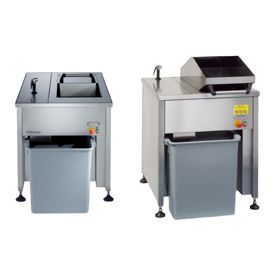
C INSTRUCTIONS FOR THE USER C1 GENERAL INFORMATION ON ORGANIC FOOD WASTE PROCESSING The COMPACT Organic Waste Food Macerator and Water Separator Unit has been designed for simple use and operation. The principle function of the COMPACT is to reduce surplus food / organic waste into a manageable volume in a cost effective manner. -
Page 13: C1.3 Materials Not Allowed At All
Fish Skin – Uncooked This product is not recommended to be processed in this unit. Fish skin tends to twist and become MAX PERCENTAGE ALLOWED : 20% of like rope and will not pass through the unit. the mix Mussels shells MAX PERCENTAGE ALLOWED : 5% of the mix C1.3 MATERIALS NOT ALLOWED AT ALL FOR PROCESSING... -
Page 14: C3 Operating Procedure
C3 OPERATING PROCEDURE C3.1 DAILY START UP Check any loose leads there are no leaks, and inlet chute and waste discharge chutes are free of obstacles or foreign matter. Ensure waste bin is empty, clean and in position. Pull out EMERGENCY STOP switch, wait 3 seconds to reset. Press Green START BUTTON and operate for one cycle without load, towards the end of the cycle (approximately 1 minute) open chute ensure that machine stops. -
Page 15: C4 Waste Bin (Disposal Of Organic Waste)
C4 WASTE BIN (DISPOSAL OF ORGANIC WASTE) The collection bin is located at the front of the COMPACT (note photograph below). Ensure that it is directly beneath the exit chute of the Press to prevent spilling of waste product. It is important that the waste bin is correctly positioned and NOT overfilled with waste. -
Page 16: C5.1 Cleaning The Unit
SHOWER LID/CHUTE CONTROL SWITCHES C5.1 CLEANING THE UNIT It is recommended that at the end of each shift or if the unit is to be shut down that it is cleaned manually. Flushing through can be activated whilst running by holding the GREEN start button down. Do not put any cleaning tools (brushes or rags) into the machine at any time. - Page 17 D TROUBLESHOOTING IMPORTANT SAFETY INSTRUCTIONS ONLY AUTHORISED QUALIFIED PERSONAL SHOULD CARRY OUT FAULT FINDING, SERVICE, MAINTENANCE AND REPAIR TASKS ELECTRICITY IS DANGEROUS! ISOLATE ELECTRICITY AND WATER SUPPLIES AT MAINS BEFORE CONDUCTING REPAIRS! INTRODUCTION The COMPACT is equipped with warning lights intended to assist with fault diagnosis, these being in the START/STOP BUTTON and The ELECTRICAL CONTROL BOX located behind the lower front panel.
- Page 18 led indicators are located on the running time adjustment edge of the circuit board (note: the a) left (no1) potentiometer adjusts cover has been removed from the machine running time from 30 & 240 electrical control box for illustration seconds purposes) b) right (no2) potentiometer adjusts pump running time from 1 to 30...
- Page 19 BASIC FAULT FINDINGS/TROUBLESHOOTING Machine does not operate- Check Chute Lid is closed Check emergency switch is pulled out Check Power Supply – plug in / switch on Check in electrical control box No 1 LED is on – if on Check motor protectors If off –...
- Page 20 Check for fluid leakage from Disposer, Press and Pump drain holes Pump Press Disposer Drain Hole Locations Arrowed The Manufacturer reserves the right to modify the appliances presented in this publication without notice. Electrolux Professional S.p.A. viale Treviso, 15, Pordenone (PN), Italy. Page 20 of 20...