Table of Contents
Available languages
Available languages
Quick Links
Technology for life safety and security
Ihr Partner in allen
Sicherheitsfragen
Internet: www.igs-hagen.de
Email: [email protected]
Montage-Anschluss-Anleitung
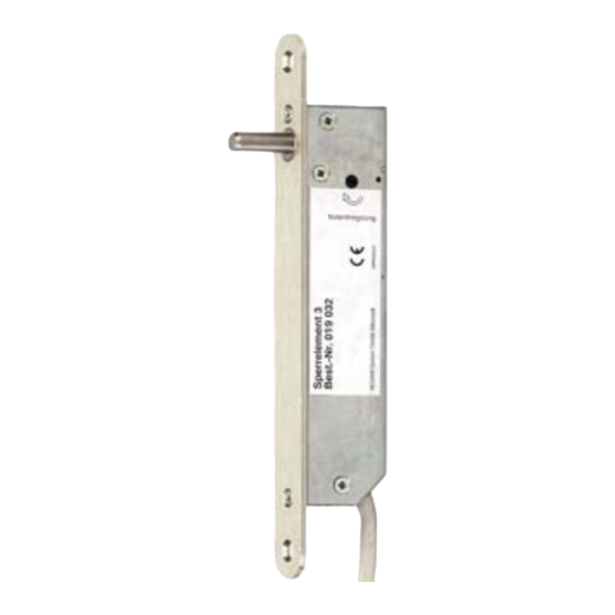
Elektromechanisches Sperrelement 3
Art.-Nr. 019032
P00731-10-002-08
2008-08-13
IGS
IGS -
Industrielle Gefahren-
meldesysteme GmbH
Hördenstraße 2
58135 Hagen
Tel.: +49 (0)2331 9787-0
Fax: +49 (0)2331 9787-87
Inhalt:
1. Allgemeines . . . . . . . . . . . . . . . . . . . . . . . . . 2
2. Funktionsbeschreibung . . . . . . . . . . . . . . . . 2
3. Montagehinweise . . . . . . . . . . . . . . . . . . . . . 4
4. Ansteuerungsmöglichkeiten . . . . . . . . . . . . . 8
5. Anschlussplan . . . . . . . . . . . . . . . . . . . . . . . 9
6. Ansteuerung mehrerer Sperrelemente . . . . 10
7. Notentriegelung . . . . . . . . . . . . . . . . . . . . . 10
8. Technische Daten . . . . . . . . . . . . . . . . . . . . 11
9. Zubehör . . . . . . . . . . . . . . . . . . . . . . . . . . . 12
3.1 Maßzeichnung . . . . . . . . . . . . . . . . . . . 4
3.2 Einbaurichtlinien . . . . . . . . . . . . . . . . . . 5
des
Bolzen-Gegenstücks . . . . . . . . . . . 7
7.1 Elektrische Notentriegelung . . . . . . . . 10
7.2 Mechanische Notentriegelung . . . . . . 10
G104003 (EMA)
Z104003 (ZKA)
D
Änderungen
vorbehalten
GB
Seite
Chapters
Table of Contents

Related Manuals for Honeywell Electromechanical Blocking Element 3


Summary of Contents for Honeywell Electromechanical Blocking Element 3
-
Page 1: Table Of Contents
Technology for life safety and security IGS - Industrielle Gefahren- meldesysteme GmbH Ihr Partner in allen Sicherheitsfragen Hördenstraße 2 58135 Hagen Internet: www.igs-hagen.de Tel.: +49 (0)2331 9787-0 Email: [email protected] Fax: +49 (0)2331 9787-87 Montage-Anschluss-Anleitung Elektromechanisches Sperrelement 3 Art.-Nr. 019032 Inhalt: Seite 1. -
Page 2: Allgemeines
Montage-Anschluss-Anleitung Elektromechanisches Sperrelement 3 Allgemeines Mit dem motorisch betriebenen Sperr- und Verriegelungselement wird der Zugang zum scharfgeschalteten Bereich einer Einbruchmeldeanlage (EMA) verhindert. Der Einsatz eines Sperrelements bringt folgende Vorteile: Die Scharfschaltung einer EMA kann durch verschiedene Scharfschaltorgane an beliebiger Stelle erfolgen. Der Zugang zum gesicherten Bereich kann an einer oder mehrerer Stellen verhindert bzw. - Page 3 Montage-Anschluss-Anleitung Elektromechanisches Sperrelement 3 Integrierte Magnetkontakte Im Sperrelement sind 2 Magnetkontakte (Reedkontakte) integriert, welche über einen gemeinsamen Magnet in der Tür angesteuert werden. Die beiden Funktionen sind: 1. Öffnungsüberwachung Der erste Kontakt (externer Kontakt) dient der Öffnungsüberwachung. Damit kann die Öffnungsüberwachung der Tür ohne zusätzlichen Kontakt realisiert werden. Der Kontakt entspricht der VdS-Klasse B.
-
Page 4: Montagehinweise
Montage-Anschluss-Anleitung Elektromechanisches Sperrelement 3 Montagehinweise Maßzeichnung Alle Maße in mm 18,7 Bolzenendstellung ±1.0 ±1,0 Einschraubmuffe mit Innensechskant für den Einbau in Holztüren (Art.-Nr. 019020) Spalt zwischen Stulp und Tür: max. 4 mm 10 max. Magnethalter Magnet Anschlusskabel 12adrig Magnet- kontakte Magnethalter mit Magnet Der Magnet wird an einer der beiden möglichen Stellen montiert (A oder B). -
Page 5: Einbaurichtlinien
Montage-Anschluss-Anleitung Elektromechanisches Sperrelement 3 Einbaurichtlinien Das Sperrelement wird in den Türrahmen, die Einschraubmuffe und der Magnet gegenüber in das Türblatt montiert. so nicht! oder so Sperrelement ACHTUNG: Um das Sperrelement zu einem späteren Zeitpunkt ggf. wieder ausbauen zu können, ist auf eine ausreichende Kabelreserve zu achten. Verlegen Sie das Kabel bis zum nächsten Verteiler in einem Leerrohr. - Page 6 Montage-Anschluss-Anleitung Elektromechanisches Sperrelement 3 Der Abstand zwischen Stulp und Einschraubmuffe sollte so klein wie möglich gehalten werden. Er darf aber keinesfalls mehr als 4 mm betragen. Der seitliche Versatz zwischen Kontakt und Magnet darf in alle Richtungen 10mm nicht überschreiten Für Türblätter aus Holz eignet sich die Einschraubmuffe (Art.-Nr.
-
Page 7: Einbauhilfe Zur Positionierung
Montage-Anschluss-Anleitung Elektromechanisches Sperrelement 3 Einbauhilfe zur Positionierung des Bolzen-Gegenstücks Zur exakten Ermittlung der Position des Gegen- stücks im Türblatt bieten wir folgendes Hilfsmittel an: Einbauhilfe, Art.-Nr. 019028 (zur Steuerung des Bolzens) Nach erfolgtem Einbau des Sperrelements in den Türrahmen verfahren Sie wie folgt: Tür öffnen Schließen Sie das Sperrelement gemäß... -
Page 8: Ansteuerungsmöglichkeiten
Montage-Anschluss-Anleitung Elektromechanisches Sperrelement 3 Ansteuerungsmöglichkeiten Das Sperrelement ist mit einem geschirmten flexiblen Kabel versehen, mit dem sämtliche elektrische Verbindungen hergestellt werden können. Der Verschlussbolzen wird bei einer entsprechenden Ansteuerung durch den Motor aus- bzw. eingefahren. Ansteuerung ist auf insgesamt 6 verschiedene Arten möglich (siehe Abbildung unten). -
Page 9: Anschlussplan
Montage-Anschluss-Anleitung Elektromechanisches Sperrelement 3 Anschlussplan Sperrelement 3 +U_b +12 V DC Bolzenendstellung Offen Offen I_max=50 mA interner Magnetkontakt Schirm externer Magnetkontakt zur vom vorigen Kontakt zum nächsten Kontakt Öffnungsüberwachung oder von der Zentrale oder Abschlusswiderstand Eingang Ausgang Anschluss des Magnetkontaktes in Z-Verdrahtung: Zum Anschluss des Kontaktes muss die kurzgeschlossene Verbindung ausgemessen werden. -
Page 10: Ansteuerung Mehrerer Sperrelemente
Montage-Anschluss-Anleitung Elektromechanisches Sperrelement 3 Ansteuerung mehrerer Sperrelemente Kommen mehrere Sperrelemente zum Einsatz, werden die Steuereingänge aller be- teiligten Sperrelemente parallel geschaltet. Alle Sperrelemente werden gleichzeitig betätigt. Beachten Sie dabei die Gesamtstromaufnahme. Die Stromversorgung muss den Strom zur gleichzeitigen Betätigung aller Sperrelemente aufbringen können. -
Page 11: Technische Daten
Montage-Anschluss-Anleitung Elektromechanisches Sperrelement 3 Technische Daten Betriebsnennspannung U_b 12 V DC Betriebsspannungsbereich 9 V bis 15 V DC Stromaufnahme in Ruhe bei U_b=12 V DC typ. 6,0 mA mittlere Stromaufnahme (ca. 1 Sek.) typ. 0,2 Strombelastbarkeit der Ausgänge (High aktiv) 50 mA max. -
Page 12: Zubehör
Nicht möglich bei Verwendung der Magnetkontakte! 14,5 14,5 Gegenstück 12 mm Gegenstück 15 mm Art.-Nr. 019022 Art.-Nr. 019023 Eintauchtiefe beachten! Ggf. muss das Gegenstück hinten aufgebohrt werden. Honeywell Security Deutschland Novar GmbH Johannes-Mauthe-Straße 14 P00731-10-002-08 D-72458 Albstadt 2008-08-13 www.honeywell.com/security/de © 2008 Novar GmbH... - Page 13 Mounting and Connection Instructions Electromechanical Blocking Element 3 Item no. 019032 Contents Page 1. General ......14 2.
-
Page 14: General
Mounting and Connection Instructions Blocking Element 3 General The motor-powered blocking- and locking element prevents access to the armed zone of an intrusion detection system. (IDS). The use of a blocking element has the following advantages: An IDA can be armed by different arming elements at different positions. Access to the secured zone can be prevented or authorized at one or several locations. - Page 15 Mounting and Connection Instructions Blocking Element 3 Integrated magnetic contacts Two magnetic contacts (Reed contacts) that are actuated via a common magnet in the door are integrated in the blocking element. The two functions are: 1. Monitoring of opening The first contact (external contact) is for monitoring opening and enables the opening of the door to be monitored without an additional contact.
-
Page 16: Mounting Instructions
Mounting and Connection Instructions Blocking Element 3 Mounting instructions Dimensioned drawing All dimensions in mm 18,7 End position of bolt ±1.0 Threaded sleeve with hexagon socket for mounting in wooden doors (Item no. 019020) distance between face plate and door max. 4 mm 10 max. -
Page 17: Installation Guidelines
Mounting and Connection Instructions Blocking Element 3 Installation guidelines The blocking element is mounted in the door frame, the threaded sleeve and the magnet in the door leaf. Incorrect! Correct Sperrelement ATTENTION: In order to be able to remove the locking element at a later date, ensure that the cable is long enough. - Page 18 Mounting and Connection Instructions Blocking Element 3 The distance between the face plate and the threaded sleeve should be kept as small as possible and should not exceed 4 mm. Æ A borehole is required in the frame ( 6 mm) for mechanical emergency unlocking. If necessary, this can be attached using the drilling jig or according to the dimensioned drawing 3.1 The installation of the blocking element in magnetic conductive metals influences the...
-
Page 19: Installation Aid For Positioning The Bolt Counter Unit
Mounting and Connection Instructions Blocking Element 3 Installation aid for positioning the bolt counter unit For determining exactly the position of the counter unit in the door leaf, we offer the following aid: - Installation aid, Item no. 019028 (for controlling the bolt ) After successfully installing the blocking element in the door frame, proceed as follows: Open the door... -
Page 20: Actuation Possibilities
Mounting and Connection Instructions Blocking Element 3 Actuation possibilities The blocking element has an 12 core shielded cable for all electrical connections. The locking bolt is extended or retracted by a motor when actuated. There are 6 different types of actuation with a choice between static operation (4.1) and dynamic operation (4.2) with different polarity of control signals. -
Page 21: Connection Diagram
Mounting and Connection Instructions Blocking Element 3 Connection diagram Blocking element 3 +U_b +12 V DC blue black Close yellow Open pink Close green Open Bolt end position Open brown Open Closed grey Closed I_max=50 mA white white internal white magnetic contact white Shield... -
Page 22: Actuation Of Several Blocking Elements
Mounting and Connection Instructions Blocking Element 3 Actuation of several blocking elements If several blocking elements are used, the control inputs of all involved blocking elements are connected parallel. All blocking elements are activated simultaneously. Pay attention to the total current consumption. The current supply must provied sufficient current for the simultaneous acti- vation of all blocking elements. -
Page 23: Technical Data
Mounting and Connection Instructions Blocking Element 3 Technical data Rated operating voltage U_b 12 V DC Operating voltage range 9 V to 15 V DC Current consumption in idle at U_b=12V DC 6.0 mA Mean current consumption (max. 0.6 sec.) Approx. -
Page 24: Accessories
14,5 Counter unit 12 mm Counter unit 15 mm Item no. 019022 Item no. 019023 Observe penetration depth! If necessary, bore the counter unit at the back. Honeywell Security Deutschland Novar GmbH Johannes-Mauthe-Straße 14 P00731-10-002-08 D-72458 Albstadt 2008-08-13 www.honeywell.com/security/de © 2008 Novar GmbH...