
Related Manuals for Siemens 1D Series


Summary of Contents for Siemens 1D Series
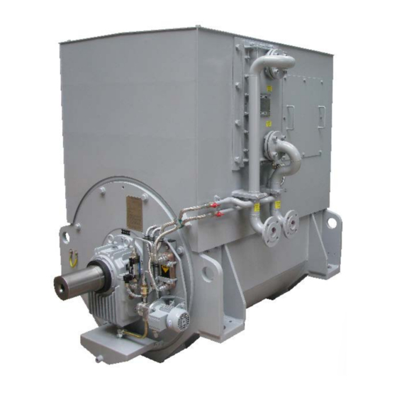
- Page 1 Operating manual Synchronous Generator Siemens Electric Machines s.r.o. Drásov 126 CZ 664 24 Drásov http://www.siemens.cz/semd...
- Page 2 Dear customers, Now you become the owners of a synchronous generator produced by the Siemens Electric Machine, s.r.o. It is a product of the company with many-years' tradition that was produced on the basis of operational experience by a team of experts and skilled workers and which incorporates the latest know-how and advanced technology.
- Page 3 Rev. Revised items Date Name 4.2.6 Fill the bearings with oil, oil cleanliness 22.02.13 Vesely 3.2.5 Anticorrosion treatment of machined parts and bearings 07.03.13 Pochop 3.2 Storage conditions 4.2.9 Alignment (rolling bearings) 14.03.13 Pochop 4.2.10 Alignment (slide bearings) 4.2.12 Checking the insulation resistance of stator winding 4.2.13 Insulation test for stator winding 05.09.13 Vesely...
-
Page 4: Table Of Contents
Contents page Generally ............................. 7 Significant (relevant) terms ......................8 General safety information ......................8 Type marking of generators ......................10 Description ............................11 Technical description, variants ....................11 2.1.1 Machine ends designation ....................... 11 2.1.2 Cooling method, ventilation ....................12 2.1.3 Rotor ............................ - Page 5 4.3.2 Making the electrical connections.................... 30 4.3.3 Safeguarding .......................... 30 First start and operation ......................30 4.4.1 Installation ..........................30 4.4.2 Change of rotating direction....................31 4.4.3 Operation ..........................31 4.4.4 Check of operation ........................31 4.4.5 Intervals of preventive inspections ................... 31 4.4.6 Putting out of operation ......................
- Page 6 Tab. 5 Minimum value of insulation resistance .................... 27 Tab. 6 Tightening torques for screwed electrical connections ..............29 Tab. 7 Minimum air distance ........................30 Tab. 8 Visual inspection of the machine ...................... 30 Tab. 9 Mechanical causes ........................... 33 Tab.
-
Page 7: Generally
All obligations of SIEMENS result from existing purchase contract that also contains complete and valid delimitation of warranties. These contractual warranty contracts are neither limited nor extended by elaboration of these instructions and documentation. -
Page 8: Significant (Relevant) Terms
1.1 Significant (relevant) terms Warning terms such as DANGER, WARNING, CAUTION and RECOMMENDATION which are mentioned in this operational instructions are used to inform about danger or extraordinary information that require special marking. DANGER means that in case a person does not adhere to it, his life can be jeopardised or he may cause damage to property. - Page 9 If there are any discrepancies, especially missing information which specify a product, sales department of SIEMENS is in charge of providing necessary explanation. Concerning this matter we ask you to mention mainly type and production number of a machine, please.
-
Page 10: Type Marking Of Generators
Type marking of generators 1 D C 06 24- 4 A V 03 -Z Synchronous machine Number of pole pairs Rotor type cylindrical rotor salient pole rotor Stator frequency and voltage Hz/kV cylindrical rotor, steam and gas turbine B 50/ <6.3 Salient pole rotor, water turbine C 50/ 6.3 Salient pole rotor, piston machine... -
Page 11: Description
2 Description 2.1 Technical description, variants Machines series, 1D are three-phase brushless synchronous LV and HV generators with a salient-type or cylindrical rotor. They consist of an AC generator (main machine) and an exciter with rotating rectifier. Main machine and exciter rotors are fitted together with rotating rectifier and fan on the same shaft. Voltage regulating parts are located in a terminal box or belong to machine supply being installed in switchboard. -
Page 12: Cooling Method, Ventilation
2.1.2 Cooling method, ventilation Ventilation method is based on operating conditions and client’s demands. Machine cooling proceeds by two methods: in the first one open ventilation system (Fig. 3) sucks ambient air to cool the winding, warmed air is exhausted by fan to the atmosphere on AS side. The other cooling method makes use of internal cooler (Fig. -
Page 13: Rotor
2.1.3 Rotor Main machine and exciter rotors are fitted together with rotating rectifier and fan on the same shaft. Generator rotor is a compact component with cylindrical or salient-type poles and a squirrel-cage damper in a magnetic field. The rotor itself is supported by two bearings and is extended at the drive end. It is press-fitted on the shaft and excited by an integrated exciter. -
Page 14: Asymmetric Load
2.2.5 Asymmetric load Asymmetric load according to IEC 60034-1-22 2.2.6 Short-circuit current During symmetrical three-phase short-circuit the value of short-time short-circuit current makes minimally triple of nominal current. Short-circuit current must be switched off within 3 s. 2.2.7 Radio interference elimination Generators correspond to interference elimination degree according to IEC 60034-1. -
Page 15: Transport And Storage
3 Transport and storage 3.1 Safety recommendation ! WARNING. During any lifting or transport of an aggregate it is necessary to use only openings that are provided for lifting and transportation, gripping lugs or pins in foundation plate! Lifting should be performed for axially symmetrical places at least see (Fig. -
Page 16: Storage Conditions
For some additional information about long term storage of entire machine or its parts (bearings, etc) please ask Siemens Electric Machines s.r.o (see chapter 10) for manual Storage of motors and generators. -
Page 17: Sleeve Bearings
Roller bearing lubricant At storage longer than 3 years, bearing lubricant must be completely replaced – type of lubricant is according to customer’s specification or contact Siemens service. See disassembly procedure of the roller bearings and lubricant renewal in customer documentation. -
Page 18: Putting Into Operation After Storage Period
3.4 Putting into operation after storage period The steps bellow must be done before putting machine into operation after storage period. Complete procedure for motor installation with all steps included you can find in chapter Unpacked carefully sealed packed machine without damaging the machine itself Check visually whole machine internals for corrosion and other deficiency in primer coating Remove completely all anticorrosion treatment on the shaft and all metal parts Measure insulation resistance –... -
Page 19: Inspection Intervals During Storage
The accuracy of the humidity indicators depends heavily on the temperature. When the ambient temperature is 20° C, they are sufficiently accurate but, at other temperatures, the humidity levels they indicate are too high. If the relative humidity rises above 60 %, a check must be made to make sure that the contents and the packing are undamaged. -
Page 20: Installation And Operation
4 Installation and operation 4.1 Safety recommendation ! WARNING Strictly adhere to ”General safety information”, please. In paragraph 1.2 of this Instructions, recommendations concerning admissible use of machine and recommendations concerning required professional knowledge that is necessary while operating heavy-current machinery. Coverings must not be opened during operation (see also paragraph 5). -
Page 21: Cooling
4.2.4 Cooling Space, in which generator is situated, must be sufficiently large and aired. Generator cannot suck warm air from other machine. For continuous operation, it is necessary to provide a steady cooling air ventilation with a volume rate according to Text of dimension drawing. ATTENTION Temperature on surface parts of electric machines (stator housing, shields) can reach over C, therefore possibility of touching these surfaces must be prevented. -
Page 22: Connecting The Oil Supply System
Specification ISO code NAS code ISO number/NAS grade ISO 17/15/12 NAS6 Tab. 2 Oil cleanliness requirements 4.2.7 Connecting the oil supply system All the information required on the connection of the oil supply system to the bearings can be found in the machine dimension drawing / dimension drawing text and in the instructions provided by the manufacturers of the bearings and the oil supply system. -
Page 23: Alignment (Rolling Bearings)
4.2.9 Alignment (rolling bearings) CAUTION Clutch cover – alignment of generator (motor) with drive machine Alignment of electric machine with drive machine and covering the clutch must be done this way, that clutch together with cover never create negative pressure on the front side of the bearing. In the case you do not keep this condition it can happen oil taking from the bearing, oil leakage and dripping through bearing seals. -
Page 24: Fig. 9 Checking The Alignment Of Shafts
Fig. 9 Checking the alignment of shafts Deviations of dimensions A and B measured at different positions may be greater than (see Tab. Diameter of flange coupling (mm) Deviation (mm) to 250 0,02 over 250 to 400 0,03 over 400 0,05 Tab. -
Page 25: Alignment (Slide Bearings)
4.2.10 Alignment (slide bearings) CAUTION Clutch cover – alignment of generator (motor) with drive machine Alignment of electric machine with drive machine and covering the clutch must be done this way, that clutch together with cover never create negative pressure on the front side of the bearing. In the case you do not keep this condition it can happen oil taking from the bearing, oil leakage and dripping through bearing seals. -
Page 26: Fig. 12 Measuring Points For Radial Alignment
IMPORTANT Measuring point 1 is always at the top; i.e. the notional measuring cross is not rotated. Calculate the mean values for the four measuring points. Measure the radial off-set between the coupling halves at four points 1, 2, 3 and 4 distributed evenly round the circumference (Fig. -
Page 27: Securing Of Mechanical Position
4.2.11 Securing of mechanical position The right position of installed and fixed generator to the foundation must be secured in such a way that set axial alignment will not be changed in the course of operation. Feet must be plugged in into the foundation. -
Page 28: Drying
Insulation test for excitation and low-voltage windings To avoid damaging the semi conductors, these have to be short-circuited. All connections of the semi conductors have to be connected to their heat sinks, i. e. the clamping covers. Low-voltage windings of MICALASTIC design are to be tested essentially the same as high-voltage windings. Since Ω... -
Page 29: Electric Installation
4.3 Electric installation 4.3.1 Making the electrical connections (cable terminal compartment for stator connection) The electrical connections inside the machine are made at the factory, taken to the cable terminal compartment for the stator connection (see text to dimension drawing) and subjected to an HV winding test. To make the stator connections, open the cable terminal compartment and the marked earthing terminals in the cable terminal compartment and the conductor clamp. -
Page 30: Making The Electrical Connections
Mechanical damage, wear, damage. When required, inform Visual inspection of the machine paint damage, corrosion, Siemens service, see page (). In case of (external, internal state) leaks, dirt, foreign bodies, detection of any moisture, it is porous seals. -
Page 31: Change Of Rotating Direction
When the check is over the whole aggregate can be launched according to operational instructions designed for the whole set. In case that the machine is not put out of operation for more than 3 months, only a visual inspection (according by Tab. -
Page 32: Putting Out Of Operation
4.4.5.2 Preventive inspection II. Is carried out regularly after 5000 operational hours from the beginning. The inspection consists of: a) Inspection of cleanliness of cooling surfaces of machine. b) Measurement of stator winding insulation resistance. c) Measurement of voltage, current, temperature, bearings and oscillations. d) Inspection of bearings operation. -
Page 33: Diagnostics Of Defects
4.5 Diagnostics of defects 4.5.1 Mechanical causes Breakdown Possible cause Remedy precaution • Contact of rotor or shaft with Find and eliminate cause solid parts of machine appears Limited access of air, excessive • Perform check of access of air, amount of dust in winding, pollution of winding, check cooler dust in cooler ducts... -
Page 34: Electric Causes I
4.5.2 Electric causes I Breakdown Possible cause Remedy precaution • Too high number of speeds Check speeds of drive • Too low number of speeds Check speeds of drive • Oscillation of number of speeds Check speeds of drive • • Check diodes, exchange diode Defect on rotating rectifier module... -
Page 35: Electric Cause Ii
4.5.3 Electric cause II Breakdown Possible cause Remedy precaution • Overload Reduce load • Break of outer wires Check outer wires Measure winding and insulation • Short-circuit of stator resistance, consult producer and winding repair • Overload Reduce load • Uneven load Adjust load Measure winding and insulation... -
Page 36: Maintenance
We are here to solve any potential uncertainty, please, contact us and provide us with type and production number of a machine. Other possibility is to contact directly SIEMENS service centre and have maintenance works performed by the centre. -
Page 37: Bearing Maintenance
WARNING Pay heed to suitable exhaust and personal protective aids (protective goggles, filter, respirator etc.) in the course of pressure cleaning! When chemical cleaners are used, please, adhere to warning and safety recommendations that are stated in appropriate list of safety data (see General safety information 1.2). -
Page 38: Disassembly And Regressive Assembly
6 Disassembly and regressive assembly 6.1 Dismantling and reassembling machines 1D This work must always take place in a clean, dust free and dry environment. Power cables must be disconnected. CAUTION! – this work may be carried out by a qualified worker only. Auxiliary circuits of regulation, checking and protective circuits are connected in an LV terminal box and are disconnected in case of a total generator dismantling only. -
Page 39: Regulation
7 Regulation 7.1 General description, control principle The purpose of the control system is to maintain a constant terminal voltage on the main machine irrespective of the load and the power factor. Voltage regulator measures generator voltage and compares it with the adjusted value. -
Page 40: Range Of Voltage Regulation
7.2 Range of voltage regulation Terminal voltage can be adjusted in the range of ±5,0% of nominal voltage by means of potentiometer that is situated on regulator. There is an option of supplying external potentiometer designed for remote control. Optionally it can be supplied with motor control. 7.3 Regulation accuracy Static accuracy of regulation is ±1% in the range from running without load up to full load as well as during constant output and change of revolutions of up to ±5,0%. -
Page 41: Neutral Wire
8 Neutral wire 8.1 Generally In the course of parallel operation of generators amongst themselves or with the line, differential currents can appear as the result of distribution harmonic oscillation of 3rd order. Differential currents are added to phase currents and can result in inadmissible raise of temperature of generators. Neutral current must not exceed 50% of nominal current. -
Page 42: Contacts
If you wish to order spare parts, please contact Customer Service or other contacts below. If you have any technical queries or you require additional information, please contact the Siemens Electric Machines or Customer Service - Manufacturer. Please have the machine data and especially machine serial number ready. - Page 43 IP 11 IM 7… no Ex protection IP 20 IM 7… Ex protection IP 21 IM B… Eex n, e IP 23 IP W24 IP 44/54/55/56 Tube IP 44/54/55/56 CACA IP 44/54/55/56 CACW Revision A 27.05.10 Siemens Electric Machines s.r.o.
- Page 44 IP 44/54/55/56 Tube IM B... E(Ex) p IP 44/54/55/56 CACA IM B... E(Ex) n, E(Ex) e IP 44/54/55/56 CACW IM 7… no Ex protection IM 7… Ex protection IM B… Eex n, e Revision A 27.05.10 Siemens Electric Machines s.r.o.
- Page 45 IP 44/54/55/56 Tube IM B... E(Ex) p IP 44/54/55/56 CACA IM B... E(Ex) n, E(Ex) e IP 44/54/55/56 CACW IM 7… no Ex protection IM 7… Ex protection IM B… Eex n, e Revision A 27.05.10 Siemens Electric Machines s.r.o.