
Related Manuals for Honeywell Ex-Or MR2500D


Summary of Contents for Honeywell Ex-Or MR2500D
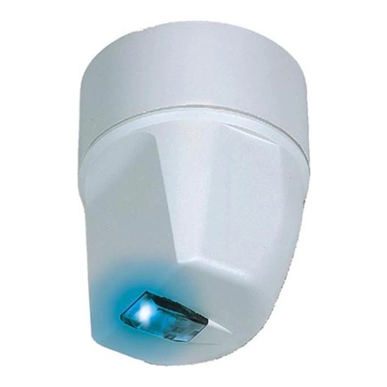
- Page 1 MR2500D / MR2500DF MR2500DALI / MR2500DALIF Mid Range Regulating LightSpot MR2500D MR2500DF MR2500DALI MR2500DALIF Installation and Commissioning Instructions Note: HP2000 required for commissioning...
- Page 2 Mid Range Regulating LightSpot Fixing Only suitably qualified personnel should install this equipment. 1. The Mid Range Regulating LightSpot is an extremely sensitive movement detector; it is essential therefore that it be installed on a rigid surface that will not itself be subject to any movement or vibration. 2.
- Page 3 Electrical Connections Mid Range Regulating LightSpot should be connected in accordance with the diagram below. Mid Range Regulating LightSpot is designed to control up to 25 DSI or DALI ballasts, a switched load of up to 10 Amps or a combination of the two. When controlling DSI or DALI ballasts the ballast types must not be mixed.
- Page 4 Commissioning The units are supplied with the factory default settings shown below which render commissioning unnecessary in many applications. To make use of the programmable settings, an infrared commissioning tool is required (HP2000). A ten-second time delay is selectable to aid commissioning. Sensitivity to Movement While the factory settings will be correct for many applications, the sensitivity can be adjusted if required.
- Page 5 Photocell Control i) Regulating Photocell Regulating photocell control tries to maintain a constant level of total illumination in the space controlled by dimming and brightening the controlled luminaires to compensate for changes in illumination from other sources. With the photocell configured as DISABLED the Regulating Control module is influenced only by the BRIGHT- OUT setting.
- Page 6 ii) The Primary Interest is the Switching Control Output With the photocell configured as ACTIVE or PASSIVE:- 1) If the lights are not already on, switch them on manually by pressing ‘UTILITIES/USER- REMOTE/Luminaire+/OK’ (HP2000) or "+" (HC5). Fluorescent lights do not reach full output until up to 15 minutes after being switched on, so ensure that the lights are fully warmed up before continuing.
- Page 7 Important Additional Notes All terminals on this product are provided for final connections. It is not intended that the product be used as a junction box for looping cables. Although nominally 12V, the dimming output is not ELV and therefore should be treated with the same respect as mains with regard to wiring practice.
- Page 8 Haydock Lane, Haydock, Merseyside WA11 9UJ the packaging and product should be disposed of via a Tel: +44 (0)1942 719229 suitable recycling centre. Fax: +44 (0)1942 272767 Do not dispose of with normal household waste. Email: [email protected] Do not burn. www.ex-or.com W4365B...