Table of Contents
Table of Contents

Related Manuals for Cisco UCS 6400 Series


Summary of Contents for Cisco UCS 6400 Series
- Page 1 Cisco UCS 6400 Series Fabric Interconnect Hardware Installation Guide First Published: 2018-08-14 Last Modified: 2020-02-28 Americas Headquarters Cisco Systems, Inc. 170 West Tasman Drive San Jose, CA 95134-1706 http://www.cisco.com Tel: 408 526-4000 800 553-NETS (6387) Fax: 408 527-0883...
- Page 2 © 2018– 2020 Cisco Systems, Inc. All rights reserved.
-
Page 3: Table Of Contents
Airflow Considerations Fabric Interconnect Weight Installation Guidelines Cabinet and Rack Requirements General Requirements for Cabinets and Racks Requirements Specific to Perforated Cabinets Unpacking and Inspecting the Cisco UCS Fabric Interconnect Required Equipment Cisco UCS 6400 Series Fabric Interconnect Hardware Installation Guide... - Page 4 Contents Installing the Cisco UCS FI in a Cabinet or Rack Establishing System Ground Proper Grounding Practices Grounding the Fabric Interconnect Starting the System C H A P T E R 3 Connecting the Cisco UCS Fabric Interconnect Preparing for Network Connections...
- Page 5 Taiwan United Kingdom Cabinet Jumper Power Cords C H A P T E R 7 Site Planning and Maintenance Records Site Preparation Checklist Contact and Site Information Chassis and Module Information Cisco UCS 6400 Series Fabric Interconnect Hardware Installation Guide...
- Page 6 Contents Cisco UCS 6400 Series Fabric Interconnect Hardware Installation Guide...
-
Page 7: Product Overview
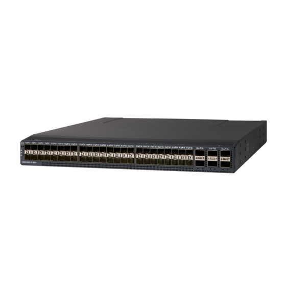
L1 or L2 port on each device. Cisco UCS 6454 Fabric Interconnect The Cisco UCS 6454 Fabric Interconnect (FI) is a 1 RU top-of-rack switch that mounts in a standard 19-inch rack such as the Cisco R Series rack. - Page 8 Cisco UCS 6454 Fabric Interconnect Note The Cisco UCS 6454 Fabric Interconnect supported 8 unified ports (ports 1 - 8) with Cisco UCS Manager 4.0(1) and 4.0(2), but with release 4.0(4) and later it supports 16 unified ports (ports 1 - 16).
-
Page 9: Cisco Ucs 64108 Fabric Interconnect
The Cisco UCS 64108 Fabric Interconnect (FI) is a 2-RU top-of-rack switch that mounts in a standard 19-inch rack such as the Cisco R Series rack. This high-density FI is an ideal upgrade from the high-density Cisco UCS 6296 Fabric Interconnect. - Page 10 System environment (fan fault) LED System status LED Beacon LED The Cisco UCS 64108 Fabric Interconnect has two power supplies (redundant as 1+1) and three fans (redundant as 2+1). Figure 4: Cisco UCS 64108 Fabric Interconnect Front View Cooling fans...
-
Page 11: Ports On The Cisco Ucs Fabric Interconnects
The ports on the fabric interconnects can be configured to carry either Ethernet or Fibre Channel traffic. You can configure only ports 1-16 to carry Fibre Channel traffic. The ports cannot be used by a Cisco UCS domain until you configure them. -
Page 12: Port Speeds And Types
The following figures show the port numbering and define port speeds and the types of ports that can be configured. For more information on how to configure the port modes, refer to "Configuring Port Modes for a Fabric Interconnect" in the Cisco UCS Network Management Guide, Release 4.0. -
Page 13: Power Supplies
• Cisco UCS 6454 -48 VDC 930 W DC (The Cisco UCS 6400 • Cisco UCS 64108 Series shares the same DC power supply and ordering PID with the Cisco UCS 6300 Series.) Cisco UCS 6400 Series Fabric Interconnect Hardware Installation Guide... -
Page 14: Fan Modules
The Cisco UCS 6454 FI and the Cisco UCS 64108 FI use different fan modules. • Cisco UCS 6454 FI: four fan modules. The fans support 3+1 redundancy. All fans are hot swappable but only one fan can be removed at a time. -
Page 15: Front Panel Ports And Leds
Front Panel Ports and LEDs The FIs in the Cisco UCS 6400 Series have slightly different front panel port and LED placement, but the icons and functions are the same. See the following figures for placement on your FI. Also see the LED state-definition table below. - Page 16 Product Overview Front Panel Ports and LEDs Figure 8: Cisco UCS 64108 FI Front Panel Ports and LEDs Beacon LED System Status LED L1 and L2 high availability ports RS-232 serial console port (RJ-45 connector) Network Management Port (RJ-45) Grounding pad for two-hole grounding lug...
-
Page 17: Network Management Port Leds
The states of the LEDs on the L1 and L2 front-panel ports are listed below. LED Position LED State Description Left No link Left Solid green Physical link Right No activity Right Blinking green Activity Cisco UCS 6400 Series Fabric Interconnect Hardware Installation Guide... -
Page 18: Rear Panel System Environment Led
Power On Self Test (POST) failed Port beacon enabled Supported Transceivers For a complete list of the supported transceivers and cables with ordering PIDs, refer to the Cisco UCS Fabric Interconnect 6454 Data Sheet. Cisco UCS 6400 Series Fabric Interconnect Hardware Installation Guide... -
Page 19: Installing The Cisco Ucs Fabric Interconnect
Statement 1017 Warning Only trained and qualified personnel must be allowed to install, replace, or service this equipment. Statement 1030 Cisco UCS 6400 Series Fabric Interconnect Hardware Installation Guide... -
Page 20: Airflow Considerations
Note Each new fabric interconnect requires a license. For information on licensing, see the Configuration Guide for the version of Cisco UCS Manager that you are using. The configuration guides are available at the following URL: Cisco UCS Manager Configuration Guides... -
Page 21: Cabinet And Rack Requirements
Note Do not use racks that have obstructions (such as power strips), because the obstructions could impair access to field-replaceable units (FRUs). The Cisco RP series PDUs, when mounted in a Cisco R Series Rack, does not obstruct FRU replacement. -
Page 22: General Requirements For Cabinets And Racks
General Requirements for Cabinets and Racks The cabinet or rack must meet the following requirements: • The minimum vertical rack space per Cisco UCS 6454 fabric interconnect must be one RU (rack unit), equal to 1.75 in. (4.4 cm). • Standard 19 in. (48.3 cm), four-post EIA cabinet or rack, with mounting rails that conform to English universal hole spacing per section 1 of ANSI/EIA-310-D-1992. -
Page 23: Required Equipment
• Tape measure and level • ESD wrist strap or other grounding device • Antistatic mat or antistatic foam The following additional items (not found in the accessory kit) are required to ground the chassis: Cisco UCS 6400 Series Fabric Interconnect Hardware Installation Guide... -
Page 24: Installing The Cisco Ucs Fi In A Cabinet Or Rack
• Wire-stripping tool Installing the Cisco UCS FI in a Cabinet or Rack This section describes how to use the rack-mount kit provided to install a Cisco UCS FI into a cabinet or rack that meets the requirements described in... - Page 25 Installing the Cisco UCS Fabric Interconnect Installing the Cisco UCS FI in a Cabinet or Rack Figure 9: Attaching the Rack-Mount Brackets to the FI Front rack-mount bracket Four M4 screws used to aligned to the rear of the attach the front bracket...
- Page 26 Figure 10: Installing the Slider Rails Step 4 Insert the FI into the rack: The UCS 6454 FI weighs 22 lb (9.97 kg) when fully loaded with components. The Cisco UCS Note 64108 FI weighs 27.4 pounds (12.4 kg) when fully loaded with components.
-
Page 27: Establishing System Ground
• You must connect both the NEBS ground connection and the power supply ground connection to an earth ground. The NEBS ground connection is required if this equipment is installed in a U.S. or European Central Office. Cisco UCS 6400 Series Fabric Interconnect Hardware Installation Guide... -
Page 28: Proper Grounding Practices
This noise source to the affected installation has a history of equipment. Best grounding malfunction due to electromagnetic recommendations must be closely noise. followed. Cisco UCS 6400 Series Fabric Interconnect Hardware Installation Guide... -
Page 29: Grounding The Fabric Interconnect
(wires) must be used and the copper conductor must comply with NEC code. Procedure Step 1 Use a wire-stripping tool to remove approximately 0.75 inches (19 mm) of the covering from the end of the grounding cable. Cisco UCS 6400 Series Fabric Interconnect Hardware Installation Guide... -
Page 30: Starting The System
Do not connect the Ethernet port to the LAN until the initial system configuration has been performed. For instructions on configuring the system, see the Configuration Guide for the version of Cisco UCS Manager that you are using. The configuration guides are available at this URL: http://www.cisco.com/c/en/us/support/... - Page 31 For a first-time installation, you will need to work with your network manager to determine the following parameters: • System name • Password for the admin account. Choose a strong password that meets the guidelines for Cisco UCS Manager passwords. This password can not be blank. • Management port IP address and subnet mask •...
- Page 32 Complete the worksheets provided in Site Preparation Checklist for future reference. Step 11 Configure the primary fabric interconnect as described in thr Configuration Guide for the version of Cisco UCS Manager that you are using. The configuration guides are available at this URL: http://www.cisco.com/...
-
Page 33: Connecting The Cisco Ucs Fabric Interconnect
The console port on a Cisco UCS fabric interconnect provides an RS-232 serial connection over an RJ-45 interface. This interface can be used for the following tasks: •... - Page 34 A session window will start and you will see one of the following prompts: loader> switch(boot)# FI-A(local-mgmt)# You now have terminal access. Depending on the prompt, you may have all Cisco UCS Manager CLI commands or a very abbreviated set of configuration commands. Cisco UCS 6400 Series Fabric Interconnect Hardware Installation Guide...
-
Page 35: Connecting The Management Port
To prevent an IP address conflict, do not connect the management port to the network until the initial configuration is complete. For configuration instructions, see the Configuration Guide for the version of Cisco UCS Manager that you are using. The configuration guides are available at this URL: http://www.cisco.com/... -
Page 36: Removing A Transceiver
Press the SFP28 transceiver inward and upward into the cage. Next, lower the bale clasp and pull the SFP28 transceiver straight out with a slight upward lifting force. Be careful not to damage the port cage during this process. Cisco UCS 6400 Series Fabric Interconnect Hardware Installation Guide... -
Page 37: Installing Or Removing Cables Into Sfp28 Trancsceivers
If the cable does not install easily, ensure that it is correctly positioned before continuing. For instructions on verifying connectivity, see the Configuration Guide for the version of Cisco UCS Manager that you are using. The configuration guides are available at this URL: http://www.cisco.com/c/en/us/support/... -
Page 38: Maintaining Sfp28 Transceivers And Fiber-Optic Cables
Refer to fiber-optic cleaning procedures for your site. • Inspect routinely for dust and damage. If damage is suspected, clean and then inspect fiber ends under a microscope to determine if damage has occurred. Cisco UCS 6400 Series Fabric Interconnect Hardware Installation Guide... -
Page 39: Replacing Components
Disable the Smart Call Home feature in the Cisco UCS domain. d) Decommission every attached chassis in the Cisco UCS domain. For details, see the Configuration Guide for the version of Cisco UCS Manager that you are using. The configuration guides are available at this URL: http://www.cisco.com/c/en/us/support/... -
Page 40: Shutting Down A Fabric Interconnect
Use the following procedure when you need to replace a single fabric interconnect with the same model of fabric interconnect. Use Cisco UCS Manager, either the GUI or the CLI, to perform the software-related tasks mentioned in the following procedure. For additional information, refer to the Cisco UCS Manager Getting Started Guide, the Cisco UCS Manager Infrastructure Management Guide, and the instructional videos available at this URL: http://www.cisco.com/c/en/us/support/servers-unified-computing/ucs-manager/... - Page 41 Peer Fabric interconnect Mgmt0 IP Netmask: 255.255.255.0 Cluster IP address : 122.255.252.1 Physical Switch Mgmt0 IPv4 address : 122.255.252.3 Apply and save the configuration (select 'no' if you want to re-enter)? (yes/no): yes Applying configuration. Please wait. Cisco UCS 6400 Series Fabric Interconnect Hardware Installation Guide...
- Page 42 Install has been successful. Firmware Updation Successfully Completed. Please wait to enter the IP address Peer Fabric interconnect Mgmt0 IPv4 Address: xx.xx.xx.xx Peer Fabric interconnect Mgmt0 IPv4 Netmask: xx.xx.xx.xx Cluster IPv4 address : xx.xx.xx.xx Cisco UCS 6400 Series Fabric Interconnect Hardware Installation Guide...
-
Page 43: Removing A Cisco Ucs Fabric Interconnect From A Rack
Procedure Step 1 Ensure that the weight of the Cisco UCS Fabric Interconnect is fully supported and that the chassis is being held by another person. Step 2 Remove the two screws holding the grounding cable to the chassis (if installed). -
Page 44: Repacking The Cisco Ucs Fabric Interconnect For Return Shipment
Remove the screws fastening the front rack-mount brackets to the mounting rails. Step 6 Gently slide the Cisco UCS Fabric Interconnect toward you, off of the slider rails and out of the rack. Repacking the Cisco UCS Fabric Interconnect for Return... -
Page 45: Technical Specifications
Description Specification Dimensions • Height: 3.38 in. (85.9 mm) • Width: 17.41 in. (442.3 mm) • Length: 24.14 in. (613.2 mm) Weight 27.4 pounds (12.4 kg) (with two power supplies installed) Cisco UCS 6400 Series Fabric Interconnect Hardware Installation Guide... -
Page 46: Power Specifications
You cannot mix power supply types in a Cisco UCS Fabric Interconnect. Note The Cisco UCS 6454 FI and the UCS 6300 Series FIs use the same 650 W AC power supplies, so the ordering PIDs are the same. Table 7: UCS 6454 FI Only: 650 W AC Power Supply Specifications (UCS-PSU-6332-AC) - Page 47 Certified) Note The Cisco UCS 6400 Series FIs and the UCS 6300 Series FIs use the same 930 W DC power supplies, so the ordering PIDs are the same. Table 9: UCS 6400 Series FIs: 930 W DC Power Supply Specifications (UCS-PSU-6332-DC)
-
Page 48: Transceiver Specifications
General Specifications for Cisco Fibre Channel SFP Transceivers The table below lists the general specifications for Cisco Fibre Channel SFP transceivers at 4 Gbps. Table 12: General Specifications for Cisco Fibre Channel SFP Transceivers at 4 Gbps Description... - Page 49 Technical Specifications General Specifications for Cisco Fibre Channel SFP Transceivers Description Short Wavelength Transmit power -9 to -2.5 dBM Approximate; actual distance may vary depending on fiber quality and other factors. Cisco UCS 6400 Series Fabric Interconnect Hardware Installation Guide...
- Page 50 Technical Specifications General Specifications for Cisco Fibre Channel SFP Transceivers Cisco UCS 6400 Series Fabric Interconnect Hardware Installation Guide...
-
Page 51: Cable And Port Specifications
C H A P T E R Cable and Port Specifications • Accessory Kit for the Cisco UCS Fabric Interconnect, on page 45 • Console Cable, on page 46 • Console Port, on page 46 • Supported AC Power Cords and Plugs, on page 47... -
Page 52: Console Cable
Console Port The console port is an asynchronous RS-232 serial port with an RJ-45 connector. The table below lists the pinouts for the console port on the Cisco UCS 6454 Fabric Interconnect. Cisco UCS 6400 Series Fabric Interconnect Hardware Installation Guide... -
Page 53: Supported Ac Power Cords And Plugs
IEC C14 connector on the end that plugs into an IEC C13 outlet receptacle. Note Only the regular power cords or jumper power cords provided with the chassis are supported. Argentina Power Cord—SFS-250V-10A-AR Plug—250 VAC 10 A IRAM 2073 Length—8.2 feet / 2.5 meters Cisco UCS 6400 Series Fabric Interconnect Hardware Installation Guide... -
Page 54: Australia And New Zealand
Power Cord—CAB-9K10A-AU Plug—250 VAC 10 A 3112 Length—8.2 feet / 2.5 meters Figure 15: CAB-9K10A-AU Peoples Republic of China Power Cord—SFS-250V-10A-CN Plug—250 VAC 10 A GB 2009 Length—8.2 feet / 2.5 meters Cisco UCS 6400 Series Fabric Interconnect Hardware Installation Guide... -
Page 55: Europe
Plug—250 VAC 10 A M 2511 Length—8.2 feet / 2.5 meters Figure 17: CAB-9K10A-EU India, South Africa, and United Arab Emirates Power Cord—SFS-250V-10A-ID Plug—250 VAC 16A EL-208 Length—8.2 feet / 2.5 meters Cisco UCS 6400 Series Fabric Interconnect Hardware Installation Guide... -
Page 56: Israel
Figure 18: SFS-250V-10A-ID Israel Power Cord—SFS-250V-10A-IS Plug—250 VAC 10 A SI32 Length—8.2 feet / 2.5 meters Figure 19: SFS-250V-10A-IS Italy Power Cord—CAB-9K10A-IT Plug—250 VAC 10 A CEI 23-16 Length—8.2 feet / 2.5 meters Cisco UCS 6400 Series Fabric Interconnect Hardware Installation Guide... -
Page 57: North America
North America CAB-AC-250V/13A Power Cord—CAB-AC-250V/13A Plug—250 VAC 13 A IEC60320 Length—6.6 feet / 2.0 meters Figure 21: CAB-AC-250V/13A CAB-N5K6A-NA Power Cord—CAB-N5K6A-NA Plug—250 VAC 13 A NEMA 6-15 Length—8.2 feet / 2.5 meters Cisco UCS 6400 Series Fabric Interconnect Hardware Installation Guide... -
Page 58: Switzerland
Figure 22: CAB-N5K6A-NA Switzerland Power Cord—CAB-9K10A-SW Plug—250 VAC 10 A MP232 Length—8.2 feet / 2.5 meters Figure 23: CAB-9K10A-SW Taiwan Power Cord—CAB-ACTW Plug—125 VAC, 10 A, CNS10917 Length—7.5 feet / 2.3 meters Cisco UCS 6400 Series Fabric Interconnect Hardware Installation Guide... -
Page 59: United Kingdom
Plug—250 VAC 10 A BS1363 (13 A fuse) Length—8.2 feet / 2.5 meters Figure 25: CAB-9K10A-UK Cabinet Jumper Power Cords Jumper Power Cord—CAB-C13-C14-JMPR Plug— 250 VAC 10 A, C13-C14 Connectors Length—2.2 feet / 0.7 meters Cisco UCS 6400 Series Fabric Interconnect Hardware Installation Guide... - Page 60 Jumper Power Cord—CAB-C13-C14-AC Plug— 250 VAC 10 A, C13-C14 Connectors Length—9.8 feet / 3 meters Figure 27: CAB-C13-C14-AC Jumper Power Cord—CAB-C13-C14-2M Plug— 250 VAC 10 A, C13-C14 Connectors Length—6.6 feet / 2 meters Cisco UCS 6400 Series Fabric Interconnect Hardware Installation Guide...
- Page 61 Cable and Port Specifications Cabinet Jumper Power Cords Figure 28: CAB-C13-C14-2M Cisco UCS 6400 Series Fabric Interconnect Hardware Installation Guide...
- Page 62 Cable and Port Specifications Cabinet Jumper Power Cords Cisco UCS 6400 Series Fabric Interconnect Hardware Installation Guide...
-
Page 63: Site Planning And Maintenance Records
Table 15: Site Planning Checklist Task No. Planning Activity Verified By Time Date Space evaluation: • Space and layout • Floor covering • Impact and vibration • Lighting • Maintenance access Cisco UCS 6400 Series Fabric Interconnect Hardware Installation Guide... - Page 64 • Dedicated circuit for power supply • Dedicated (separate) circuits for redundant power supplies • UPS for power failures Grounding evaluation: • Circuit breaker size • CO ground (AC- powered systems) Cisco UCS 6400 Series Fabric Interconnect Hardware Installation Guide...
-
Page 65: Contact And Site Information
Use the following worksheet to record contact and site information. Table 16: Contact and Site Information Contact person Contact phone Contact e-mail Building/site name Data center location Floor location Address (line 1) Address (line 2) Cisco UCS 6400 Series Fabric Interconnect Hardware Installation Guide... -
Page 66: Chassis And Module Information
System IP address System IP netmask Hostname Domain name IP broadcast address Gateway/router address DNS address Modem telephone number Table 18: Module Information Slot Module Type Module Serial Number Notes Fixed Expansion Cisco UCS 6400 Series Fabric Interconnect Hardware Installation Guide... - Page 67 Chassis and Module Information Table 19: Fabric Interconnect Port Connection Record Fabric Interconnect A or B Connected to Slot Port Chassis Port LAN or SAN Port Connection Pin Group Channel Notes Group Cisco UCS 6400 Series Fabric Interconnect Hardware Installation Guide...
- Page 68 Site Planning and Maintenance Records Chassis and Module Information Fabric Interconnect A or B Connected to Slot Port Chassis Port LAN or SAN Port Connection Pin Group Channel Notes Group Cisco UCS 6400 Series Fabric Interconnect Hardware Installation Guide...