
Related Manuals for Huawei OptiX RTN 910A


Summary of Contents for Huawei OptiX RTN 910A
- Page 1 OptiX RTN 910A Radio Transmission System V100R010 IDU Quick Installation Guide for Outdoor Cabinets (OMB Cabinets) Issue: 01 Date: 2017-05-30 HUAWEI TECHNOLOGIES CO., LTD.
- Page 2 Notice The purchased products, services and features are stipulated by the contract made between Huawei and the customer. All or part of the products, services and features described in this document may not be within the purchase scope or the usage scope. Unless otherwise specified in the contract, all statements, information, and recommendations in this document are provided "AS IS"...
- Page 3 Huawei. The safety precautions in the document are related to only Huawei products. Huawei is not liable for any consequence that results from the violation of universal regulations for safety operations and safety codes on design, production, and equipment use.
- Page 4 Instructions and Precautions for Handling Boards Do not hold a board without hand protection. Wear an ESD wrist strip or ESD gloves before handling a board. Wearing ESD gloves Wearing an ESD strip Holding a board without hand protection Hold the front panel of a board with hands. Insert filler panels into vacant slots on an NE to prevent foreign matters from getting into the NE, which may result in faults on the NE.
- Page 5 Tools for Installation Level Phillips screwdriver Flat-head screwdriver Adjustable Wrench Long measuring tape COAX crimping tool Socket wrench Torque wrench Hex key Wire clippers RJ45 crimping tool Wire stripper Diagonal pliers Cold press pliers Needle-nose pliers Multimeter Bayonet wrench Combination pliers File Heat gun Hammer drill...
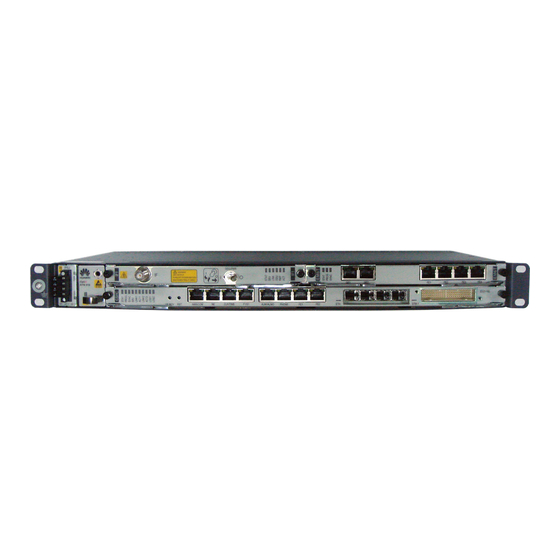
- Page 6 Introduction to the Equipment Introduction to the RTN 910A Ethernet service port (Electric) Input power port ODU power switch IF port Ethernet service port (Optical) NM/COM port External clock port E1 port USB port External time port Outdoor cabinet monitoring port NOTE The external clock port, external time port, and outdoor cabinet monitoring port share one physical port.
- Page 7 Introduction to the OMB Cabinet Front View of the OMB Cabinet Technical Specifications Dimensions (mm): 600 (H) x 240 (W) x 430 (D) Ambient temperature (no sunshine radiation): -20°C to +50°C Left View of the OMB Cabinet Right View of the OMB Cabinet...
- Page 8 About the Internal Structure of the OMB Cabinet Internal Structure of the OMB Cabinet (AC Power Supply) OMB cabinet (AC power supply) HEUA Fan assembly (internal circulating) Fan assembly (external circulating) AC/DC power supply facility PMU module AC surge protection box Internal Structure of the OMB Cabinet (DC Power Supply) OMB cabinet (DC power supply) HEUA...
- Page 9 Installation Scenarios of the Cabinets Installation Scenarios of the OMB Cabinet Dimensions of the OMB Cabinet Recommended Requirements of Minimum Requirements of the the OMB Cabinet OMB Cabinet ≥200 mm ≥200 mm ≥600 mm ≥500 mm...
- Page 10 Installation Modes Installing the OMB cabinet on a pole Installing the OMB cabinet on a wall NOTE The OMB cabinet provides a small space. Therefore, it is not recommended that you use the OMB cabinet in an area where the ambient temperature is lower than –20°C in winter. It is recommended that you use the APM30H or TMC11H cabinet that is configured with a heater.
- Page 11 Install the backplane of the OMB frame on the wall. Install the OMB frame on the backplane. M6 screw Installing the OMB Cabinet on a Pole Install the lower fastener assembly on the backplane. Install the first upper fastener assembly on the pole. Flat washer Spring washer M10x180 bolt...
- Page 12 Install the backplane on the pole. Install the mounting brackets for the OMB frame. Install the OMB frame on the backplane.
- Page 13 Outdoor Pole-Mounting Scenario Dedicated Outdoor Installation Installing the RTN 910A in the OMB Cabinet (AC Power Supply) Installing the RTN 910A in the OMB Cabinet (DC Power Supply)
- Page 14 Installing the Assemblies Installing the RTN 910A CAUTION When installing the RTN 910A, ensure that the fan assembly is installed in the lower part of the cabinet. The RTN 910A must be installed on the left side of the surge-protection box (SLPU). Fan assembly Installing the SLPU CAUTION...
- Page 15 Installing and Routing the Cables Installing the PGND Cables Installing the PGND Cables for the Cabinet NOTE When installing the PGND cables in the DC powered OMB cabinet, use the same method as that in the AC powered OMB cabinet. The ground cables and signal cables must be bound separately or must be separated from each...
- Page 16 Installing and Routing the Power Cables – AC Power Supply Installing the Input Power Cable for the OMB Cabinet (AC Power Supply) Installing the Input Power Cable for the RTN 910A NOTE For AC OMB cabinets of Ver. C, connect the two power cables from RTN 910A to any two power output terminals (such as terminals LOAD6 and LOAD7) with the maximum output current of 30 A.
- Page 17 Installing and Routing the Power Cables – DC Power Supply Installing the Input Power Cable for the OMB Cabinet Installing the Input Power Cable for the RTN 910A NOTE For AC OMB cabinets of Ver. C, connect the two power cables from RTN 910A to any two power output terminals (such as terminals LOAD6 and LOAD7) with the maximum output current of 30 A.
- Page 18 Installing the Service Cables for the Equipment – AC Power Supply Installing E1 Cables E1 cables for 1xAnea 96/4xDB25 conversion are used. Rubber block Installing Ethernet Cables UFLP INSIDE OUTSIDE Rubber block...
- Page 19 Installing IF Cables Rubber block Installing Fibers Binding strap Insulation tube...
- Page 20 Installing Signal Monitoring Cables COM_IN port HEUA board TX RX 1~16 CF RCV RST NMS/COM CLK/TOD1 F1/S1 ALMI/ALMO TEL/MON/TOD2 CLK/MON/TOD port •Mapping Relationships Between the Signals over Different Cables 8 7 6 5 4 3 2 1 RJ-45 Connector of the Network Interface to the Cable RJ-45 Connector (CLK/TOD/MON) of the Network on the CMUA (COMIN) Board Port to the Cable on the RTN 910A...
- Page 21 Installing the Service Cables for the Equipment – DC Power Supply Installation Effectiveness of the Service Cables Ethernet cable (transit E1 cable (transit cable) E1 cable (lead-out cable) cable) Ethernet cable (lead-out IF cable Monitoring cable cable) Fiber NOTE For the details on how to route service cables, see “Installing the Service Cables for the Equipment –...
- Page 22 Assembling the Cable Connector Checking Cabinet Installation What to Check For The layout of the cabinet complies with the engineering designs. In pole-mounting mode, the mounting brackets are fixed securely, and the frame is fixed properly and is not distorted. In wall-mounting mode, the holes for the frame are in proper contact with the holes for the expansion bolt, and the frame and the wall surface are in proper horizontal contact.
- Page 23 Checking Electrical Connections of the Cabinet What to Check For All the self-made PGND cables are copper-based with proper wire diameters. There is no switch, fuse, or short circuit on the cable. According to the wiring diagram of the power system, the PGND cables are connected securely, the AC lead-in cables and cables inside the cabinet are connected properly, and the screws are tightened.
- Page 24 Appendixes Layout of the Cable Holes Layout of the cable holes at the left Layout of the cable holes at the right bottom of the cabinet: bottom of the cabinet: Cable Name Cable Hole Position Cable Hole Name Power input cable of an AC/DC Right cable hole Select any one.
- Page 25 Installing the Cables on the Cable Module Route the cable from the bottom of the cable trough Remove the screws from the cable upwards through the corresponding cable hole on the cable module. module, and ensure that the cable connector is idle. Remove the cable module from the cable trough.
- Page 26 HUAWEI TECHNOLOGIES CO., LTD. Huawei Industrial Base Bantian Longgang Shenzhen 518129 People’s Republic of China www.huawei.com...