
Related Manuals for Toshiba Strara CTX Series


Summary of Contents for Toshiba Strara CTX Series
- Page 1 TOSHIBA Telecommunications Division Digital Business Telephone Systems CTX100 and CTX670 Installation and Maintenance Manual September 2002...
- Page 2 Publication Information © Copyright 2002 Toshiba Information Systems (UK) Ltd. Toshiba Information Systems (UK) Ltd. reserves the right to change any of this information including, but not limited to, product characteristics and operating Telecommunications Division specifications, without prior notice. All rights reserved. No part of this manual, covered by the copyrights hereon, may be It is intended that the information contained within this manual is correct at the time of reproduced in any form or by any means—graphic, electronic, or mechanical, including...
-
Page 3: Table Of Contents
Contents Introduction Organisation ..........................ix Conventions ..........................x Related Documents/Media ....................... xi General Description ......................xi Installation and Programming ..................... xi User Guides ......................... xi Quick Reference Guides ...................... xi CD-ROMs ........................... xi Chapter 1 - Strata CTX Configuration Strata CTX100 Overview ....................... 1-1 CTX100 Processor ......................... - Page 4 Contents CTX670 Remote Expansion Cabinet ..................1-9 System Capacities .........................1-10 Universal Slot PCBs ......................1-14 Station, Line and Option PCBs ..................1-14 Functional Block Diagrams ....................1-17 Strata CTX100 Cabinet Slot Configuration Considerations ..........1-21 CTX100 Base Only: Digital Telephones and PRI lines ...........1-22 CTX100 Base & Expansion: Digital Telephones and PRI lines ........1-22 Strata CTX670 Cabinet Slot Configuration ................1-23 PCB Placement Guidelines ....................1-24 System Power Factor Check Considerations ................1-27...
- Page 5 Contents Chapter 3 - Strata CTX670 Installation Inspection ..........................3-1 Packaging and Storage ......................3-1 Site Requirements ........................3-2 Input Power ........................3-2 Clearance and Location ..................... 3-2 Power Considerations ......................3-4 Reserve Power ........................3-4 EU Registration Information ....................3-5 Cabinet Installation Considerations ..................
- Page 6 Contents PCB Installation Power Supply Considerations ..............4-2 ADKU Hardware Options ....................4-3 ADKU Installation ......................4-3 ASTU Installation ......................4-3 BDKU Hardware Options ....................4-5 BDKS ..........................4-5 BDKU Installation ......................4-5 BIOU Installation .......................4-7 BVPU Configuration ......................4-9 BVPU Installation ......................4-9 PDKU2 Hardware Options ....................4-11 PDKU2 Installation ......................4-11 R48S -48 Volt Supply Installation (Internal Option) ............4-12 External Options .......................4-13 RSTU Installation ......................4-13...
- Page 7 Contents Chapter 6 - MDF PCB Wiring Station Loop Lengths ......................6-2 Station Wiring Diagrams ......................6-4 ADKU and BDKU/BDKS Digital Station Wiring ............6-5 PDKU Digital Station Wiring ................... 6-6 Digital Telephone DSS and DDCB External Power Connection ........6-9 RSTU or PSTU Analogue Devices Wiring ..............
- Page 8 Contents Precautions ........................7-30 DKT2104-CT ........................7-31 Cordless Telephone Installation (DKT2004-CT and DKT2104-CT) ......7-31 Telephone Cord Connection ....................7-32 Connect and Apply Power to Base Unit ................7-32 Cordless Telephone Connectors ..................7-33 Handset Battery Pack Installation ..................7-34 Removing and Charging Your Battery Pack ..............7-34 Tips on Extending Battery Pack Life ................7-35 2000/2500-series Telephones ....................7-36 2000/2500-series Telephone Option PCBs ..............7-36...
- Page 9 Contents T001B Relay Unit Test ....................8-26 Power Failure Options ......................8-27 Reserve Power ......................... 8-27 Power Failure Transfer Unit .................... 8-27 Power Failure Emergency Transfer (DPFT) Installation ..........8-28 Station Message Detail Recording (SMDR) ................ 8-29 SMDR Record Types ...................... 8-29 Notes to Users Index Strata CTX I&M September 2002...
- Page 10 Contents viii Strata CTX I&M September 2002...
-
Page 11: Introduction
Introduction This manual provides detailed step-by-step instructions for installing and maintaining the Strata CTX100 and CTX670 digital business telephone systems. It is intended for qualified service technicians and system programmers. Use this manual in conjunction with the Strata CTX Programming Manual which covers the programs related to the Strata CTX100 and CTX670 systems discussed in this book. -
Page 12: Conventions
Introduction Chapter 8 – Peripheral Installation provides connection procedures for optional peripheral equipment to Strata CTX systems. The instructions include hardware requirements, PCB configuration, interconnection/wiring requirements, and programming considerations. Notes to Users Index Conventions Conventions Description Elaborates specific items or references other information. Within some tables, general notes apply to the entire table and numbered Note notes apply to specific items. -
Page 13: Related Documents/Media
CD-ROMs Strata CTX WinAdmin Application Software and Documentation Library Strata CTX Quote For authorised users, Internet site FYI (http://www.toshiba-telecoms.co.uk) contains all current Strata CTX documentation and enables you to view, print and download current publications. Strata CTX I&M September 2002... - Page 14 Introduction Strata CTX I&M September 2002...
-
Page 15: Chapter 1 - Strata Ctx Configuration
Strata CTX Configuration This chapter contains information and worksheets to help configure the Strata CTX100 and CTX670 hardware components. A system overview of both the Strata CTX100 and Strata CTX670 hardware components and the maximum station and line capacities available with the system processor is provided. -
Page 16: Ctx100 Processor
Large Scale Integrated (LSI) Circuits Custom Toshiba LSI circuits provide on-board conference switching circuits for up to eight-party conferences and digital Pad circuits to adjust audio volume levels in eight steps to compensate for conference and/or network losses. -
Page 17: Smartmedia Memory
Proprietary Voice Mail integration and system administration connection (including local and remote CTX WinAdmin). BSIS (Serial Port Interface) – Provides up to two RS-232 interface ports for SMDR interface to Call Accounting devices, SMDI or Toshiba Proprietary interface to Voice Mail devices, and two future applications. CTX100 Cabinet Slots... -
Page 18: Ctx100 License Control
The optional RS-232 serial port interface (BSIS) provides two circuits to interface with SMDI or Toshiba Proprietary Voice Mail integration, Call Accounting SMDR, and two for future applications. The first circuit does not require a license, but circuits two through four each require one CTX100 SERL LIC license. -
Page 19: Strata Ctx670 Overview
Strata CTX Configuration Strata CTX670 Overview The Strata CTX670 system provides sophisticated telecommunication features in a modular system designed for growth. Its universal slot architecture enables you to select the combination of Exchange lines, stations, and peripheral options that best suit your needs. The CTX670 basic processor can be configured for smaller systems as a one or two cabinet system with a capacity of up to 192 Exchange lines and stations combined. -
Page 20: Large-Scale Integrated (Lsi) Circuits
Strata CTX Configuration Large-scale Integrated (LSI) circuits The processor has built-in LSI circuits that support the following: 16 built-in DTMF receivers 16 built-in Busy Tone (BT) detectors for Auto Busy Redial (ABR) 64 conference circuits for up to eight party conferences. Up to 96 conference circuits are available using the BEXS. -
Page 21: Ctx670 Processor Pcb Subassemblies
The optional RS-232 serial port interface (BSIS) provides two circuits to interface with Voice Mail SMDI or Toshiba Proprietary Voice Mail integration, Call Accounting SMDR, and two for future applications. The first circuit does not require a license, but circuits two through four each require one CTX670 SERL LIC license. -
Page 22: Licensed Software Options
Strata CTX Configuration Licensed Software Options Some software options are activated with license codes. The following software options require a license: Each CTX system (node) in a Strata Net QSIG Network requires one CTX670 QSIG LIC license. A maximum of four serial network nodes are allowed in any one serial chain in the network topology. Each individual CTI Open Architecture application requires one CTX670 CSTA LIC license (maximum nine). -
Page 23: Expansion Cabinets
Strata CTX Configuration Expansion Cabinets One to six Expansion Cabinets can be added to increase the system station and Exchange line capacity. Each expansion cabinet provides 10 slots (S_01~S_10). Figure 1-4 shows an Expansion Cabinet. Refer to the following section for cabinet slot and station/line capacities. Tables 1-5 show the number of stations and Exchange lines allowed when additional cabinets and PCBs are used. -
Page 24: System Capacities
Strata CTX Configuration System Capacities This section contains Strata CTX100 and CTX670 capacities for stations and peripherals, Exchange lines, station buttons and system features. All tables apply to both systems unless otherwise noted. Important! The maximum capacities listed for the CTX100 in Tables 1-3~1-8 are based on an expanded CTX100 (Base + Expansion cabinet). - Page 25 Strata CTX Configuration Table 1-5 Station/Peripherals System Capacities (Cont.) CTX670 CTX670 CTX100 Expanded Processor Stations Basic Processor Base & Expansion BBCU + BECU + BBCU + BECU BEXS + BBMS DSS consoles (DDSS) ISDN BRI station circuits TE-1 and TA (2B+D per circuit) Off-premise stations BPCI used for TAPI only: per cabinet...
- Page 26 Strata CTX Configuration Table 1-7 Station Buttons CTX670 CTX100 CTX670 Expanded Processor Station Buttons per System Base & Basic Processor BBCU + BECU Expansion BBCU + BECU + BEXS + BBMS Call Forward, Personal CF Buttons Exchange Line Buttons Group Exchange Line Buttons Pooled Exchange Line Buttons Exchange Group and Pooled Line Buttons Station Loop Buttons...
- Page 27 Strata CTX Configuration Table 1-8 System Feature Capacities (Cont.) CTX670 CTX670 CTX100 Base Expanded Processor Features Basic Processor & Expansion BBCU + BECU BBCU + BECU + BEXS + BBMS Conference Ports Conferencing (three-parties simultaneously) Conferencing (eight-parties simultaneously) 6 lines max. 6 lines max.
- Page 28 Strata CTX Configuration Universal Slot PCBs Universal Printed Circuit Boards (PCBs) installed in the Strata CTX100 or CTX670 cabinets provide interfaces for stations, lines, and peripherals. Each PCB measures 7.5 x 5.5 inches (190 x 140 mm) and mounts in the slot with a 44-pin backplane connector. PCB external connections to station equipment are made to the Main Distribution Frame (MDF) using industry-standard connectors.
- Page 29 Strata CTX Configuration Table 1-9 Station PCBs (Cont.) Standard Telephone Interface Unit (RSTU3) Provides eight standard telephone circuits. Stutter dial Interface Options: tone is provided for Message Waiting audible Standard telephones indication. Voice mail ports Off-premises stations Other similar devices Alternate BGM source Auto Attendant digital announcer Message Waiting lamp...
- Page 30 Strata CTX Configuration Table 1-10 Exchange Line PCBs ISDN S/T-type Basic Rate Interface Unit (RBSU) Two ISDN BRI S/T point circuits (NT or TE). Each Interface Options: Network and/or station side. circuit is 2B+1D. (Host for the RBSS.) Basic Rate Interface Subassembly (RBSS) Interface Options: Station side only.
- Page 31 SMDI or Toshiba Proprietary Stratagy ES Integration (Optional) Voice Mail AMDS MOH/BGM Jack +Volume Control Remote Maintenance Modem Toshiba Proprietary Soft Key LCD Link Remote CTX WinAdmin PC RJ45 Internet AETS Ethernet Interface (CSTA) Relay Contact (Programmable) RCA Jack (600 ohm Page Output)
- Page 32 Strata CTX Configuration Up to F our P rogrammable S erial (R S -232) P ort Modular J ac ks A vailable S MDR BEC U P roc essor P C B C all A c c ounting BS IS C onferenc e S W with P A D S MDI and S tratagy ES Integration...
- Page 33 Strata CTX Configuration CTX Expansion Cabinets Optical Fiber Cable 3 km/(1.86 mi.) RRCU Remote Cabinet Interface Card CTX / DK 10BaseT BVPU IP Network Remote Location(s) BVPU Voice Over IP Unit (4 Circuits) Mode Page Scroll Feature BDKU/BDKS or PDKU IP Network Extender Gateway...
- Page 34 Strata CTX Configuration BDKU 8 Digital Telephone Circuits and Digital Telephone (DKT) BDKU/BDKS Mode Page Scroll Feature 16 Digital Telephone Circuits Spdial Redial Spkr Cnf/Trn Hold ADKU 8 Digital Telephone Circuits (max). Digital Single Line Connects audio path to Attd Console BATI Telephone (DKT) Handset...
-
Page 35: Strata Ctx100 Cabinet Slot Configuration Considerations
Strata CTX Configuration Strata CTX100 Cabinet Slot Configuration Considerations Write in the PCBs installed in each cabinet slot in the Cabinet Diagram below. Use the PCB placement guideline below to place PCBs in the correct slots. A number of tables provide CTX100 capacities and configuration examples in this section. -
Page 36: Ctx100 Base Only: Digital Telephones And Pri Lines
Strata CTX Configuration CTX100 Base Only: Digital Telephones and PRI lines RPTU2 (PRI) is limited to 48 channels. Table 1-12 CTX100 CTX Base Cabinet with PRI lines 4 Universal Slots 40 Stations (Max.) 48 lines (Max.) 64 Stations + PRI lines combined (Max.) Table No. -
Page 37: Strata Ctx670 Cabinet Slot Configuration
Strata CTX Configuration Strata CTX670 Cabinet Slot Configuration The cabinet diagram below enables you to write in the PCBs installed in each cabinet slot. Use the PCB placement guideline below to place PCBs in the correct slots. Fill in the PCBs that go into each slot. -
Page 38: Pcb Placement Guidelines
Do not skip slots except for vacant slots that provide RPTU capacity. Also, do not skip slots except for vacant slots that provide for BBKU/BDKS with Speaker OCA. Toshiba recommends placing the RPTU and BDKU/BDKS PCBs first because they have special placement rules. - Page 39 Strata CTX Configuration Cables are provided according to the connectors on the RRCU card to which they are attached. Table 1-15 for connector information. Table 1-15 Remote Cabinet Data Cables and Connectors RRCU Connectors Data Cables BDCL1A-MS1 BDCL1A-M2 BDCL1A-S2 X = Applies to connector. BIOU Interface PCB Step 3: Up to two BIOU PCBs can be installed in any local/remote cabinet slot, except the BIOU may not...
- Page 40 Strata CTX Configuration Analogue and VoIP Tie Line PCBs Step 7: RDDU, RCOU, RCOU with RCOS, RGLU, REMU, and BVPU: Each PCB or PCB combination requires one slot. These PCBs can be installed in any slot, except a slot that is left vacant to provide capacity for RPTU.
-
Page 41: System Power Factor Check Considerations
Strata CTX Configuration System Power Factor Check Considerations The Strata CTX power supply was engineered for maximum cost efficiency to provide power for the most configurations. Because of this design, there are some -24VDC power limitations for telephone option hardware. Each telephone/device and PCB has been assigned Power Factors (PFs) that reflect the amount of power supply resources they consume. - Page 42 Strata CTX Configuration Table 1-17 Strata CTX Expansion Cabinet Example Quantity +5VDC PF -24VDC PF RBSU + RBSS RCOU + RCOS Total Table 1-18 shows the individual PCB +5VDC and -24VDC power factors. Table 1-18 PCB and Power Supply Power Factors PCB Type +5VDC PF -24VDC PF...
-
Page 43: Cabinet Power Factor Check
Strata CTX Configuration Table 1-19 Power Factor Check For CTX100 Sub Total Qty. -24VDCPF +5VDCPF -24VDFPF +5VDFPF ACTU ARCS AMDS AETS BSIS BDKU BDKS 0.15 RPTU ASTU 39.0 Standard Phone Total 44.3 11.5 APSU112F Power Supply: -24VDCPF=45.0 +5VDCPF=20.0 Cabinet Power Factor Check 1. -
Page 44: Ctx670
Strata CTX Configuration CTX670 Table 1-21 CTX670 Cabinet Power Factor Check CTX670 Cabinet 1 (base) CTX670 Cabinet 2 Slot Slot Type +5VDC PF -24VDC PF Type +5VDC PF -24VDC PF B101 S201 B102 S202 S101 S203 S102 S204 S103 S205 S104 S206 S105... -
Page 45: Ctx Primary Ac And Reserve Power Considerations
Strata CTX Configuration CTX Primary AC and Reserve Power Considerations CTX100 AC Power Considerations The power supply in each Strata CTX100 Base and Expansion Cabinet furnishes power to all of the stations and some of the interface peripherals (see Table 1-22). -
Page 46: Reserve Power (Ctx100 And Ctx670)
Strata CTX Configuration Determine CTX670 system miscellaneous power components in the following worksheet. (See Tables 1-26 1-29 for component descriptions.) These components are not used on CTX100 systems. Enter the number of cabinet power components needed: Main Location ____________ Remote Location 1___ 2___ 3___ 4____5___ 6____ CTX670 Cabinet Power Enter the Number Components... -
Page 47: Primary/Reserve Power Cabinet Hardware
Strata CTX Configuration Table 1-26 CTX670 Reserve Power Characteristics Battery Charger Characteristics Maximum Battery Charger Drain (-24VDC) 1 cabinet 6.0 amps 5 cabinets 30.0 amps Charger: current limiting 2 cabinets 12.0 amps 6 cabinets 36.0 amps Nominal float voltage: 2.275 volts/cell 3 cabinets 18.0 amps 7 cabinets... - Page 48 Strata CTX Configuration Table 1-29 CTX670 Power Cabinet Hardware Option Description Strata CTX670 cabinet power supply must be ordered for each cabinet. Operates with 240VAC connected as the system’s primary AC power source. It automatically detects and adjusts to the BPSU672 type of primary AC power that is connected.
-
Page 49: Hardware Compatibility
Strata CTX Configuration Hardware Compatibility PCB compatibility for the Strata CT, CTX100 and CTX670 systems is shown in Table 1-30. Table 1-30 Hardware Compatibility Sub-assembly CTX100 CTX670 DK40 CHSUB672F CHSUE672F BPSU672F BBDB1A RCTUB/C/D B1, B2, B3, B5 (CT Processors) RRCS-4/8/12 BRCS-4/8/12 K5RCU2A KSTU3F... - Page 50 Strata CTX Configuration Table 1-30 Hardware Compatibility (Cont.) Sub-assembly CTX100 CTX670 DK40 BDKU BDKS BIOU ADKU 1. Tiu recommendation is RCOU/RSTU/PDKU should be used to maintain EMC compatibility. 2. Functions as a PDKU can not fit BDKS to this unit. 3.
- Page 51 Strata CTX Configuration Peripherals Comments CTX100 CTX670 DK40 MCK Gtwy/Extnd ADV-C-LOW-32 Oak Call Logging ADV-C-LOW-100 Oak Call Logging Mirra Voice Recorders 1. Current versions of Insight DK can be upgraded to work with CTX. There is a cost and this is arranged through Sension. 2.
- Page 52 Strata CTX Configuration 1-38 Strata CTX I&M September 2002...
-
Page 53: Chapter 2 - Strata Ctx100 Installation
Strata CTX100 Installation This chapter explains how to install the Strata CTX100 system. It includes information on site requirements, wiring diagrams, and step-by-step instructions on how to install the unit(s), the ground wiring, AC power cabling, reserve power (battery backup) cabling, and PCB cabling. Inspection 1. -
Page 54: Cabinet Size And Weight
To avoid accidental power turn-off, Toshiba recommends that you do not use an On/Off wall switch on this dedicated AC circuit. For the Strata CTX100, a reserve power source (two or four customer-supplied 12VDC batteries) may be connected to the system to serve as a power failure backup. - Page 55 Strata CTX100 Installation Front View Wall 37cm (14.5") 61cm (24") 50.6cm (19.9") 61cm (24") 37.1cm (14.6") Base Cabinet Exp Cabinet Side View Wall 25.9cm (10.2") 91.5cm (36") 36'' 5910 Figure 2-1 CTX100 Base Cabinets and Expansion Clearance Strata CTX I&M September 2002...
-
Page 56: Environmental Considerations
Strata CTX100 Installation Environmental Considerations Table 2-1 provides a summary of the environmental characteristics. Table 2-1 CTX100 Environmental Characteristics Environmental Specifications Operating temperature 32~104° F (0~40° C) Operating humidity 20~80% relative humidity without condensation Storage temperature -4~140° F (-20~60° C) BTU Rating (Base plus Expansion Cabinet) ACTU (installed) 190 Watts (56 watt hours for both cabinets) -
Page 57: Ac Power And "Protective Earth" Test
Strata CTX100 Installation An inter-cabinet ground wire connecting the Base and Expansion cabinets is not necessary. AC Power and “PROTECTIVE EARTH” Test Test the “protected earth” for continuity by measuring the resistance of the earth. This will test the earth connection and can be carried out by using a commercially available earth loop impedance meter. -
Page 58: Step 3: Check The Base/Expansion Power Supply Jumper Plug
Strata CTX100 Installation The figure below show the position of the screws. Back covers should be removed before the Note Base and Expansion cabinets are attached to each other. EXPANSION BASE Remove 1 screw 5933 Figure 2-4 Base and Expansion Cabinet Back Covers Step 3: Check the Base/Expansion Power Supply Jumper Plug The APSU112F power supply is used in both CTX100 cabinets. - Page 59 Strata CTX100 Installation 5. Secure the top two screws approximately two thirds of the way into the top two holes on the back board. 6. Hang the Base Cabinet back cover from the top two screws and then secure the top and bottom screws completely into the back board.
-
Page 60: Step 5: Mount The Expansion Cabinet (If Required)
Strata CTX100 Installation Bac k C over Hanger Bottom left hanger is only used on the Base C abinet Hanger Hole 5937 Figure 2-6 Mounting CTX100 Cabinet on Back Cover 10. Earth the system according to “AC Power and Earthing Requirements” on Page 2-4. - Page 61 Strata CTX100 Installation 8. To mount the Expansion Cabinet, position it onto the back cover hangers. Position the cabinet over the bottom right hanger first, and then carefully tilt the cover over the Note top two hangers. 9. Slide the Expansion Cabinet to the left, feeding the data ribbon cable through the side hole of the Expansion Cabinet.
-
Page 62: Step 6: Install Reserve Power
CTX100 power supply equipped with an ABCS battery charger to ensure uninterrupted system operation in the event of a power failure. The ABCS battery charger and a pre-assembled battery cable (ABTC-3M) for connecting the batteries is available from Toshiba (see Figure 2-8). - Page 63 Strata CTX100 Installation Step 6A: Install the Optional ABCS1A Battery Charger WARNING! Whenever the cabinet top cover is removed, use extreme caution. Do not touch any internal power supply components because hazardous voltages may be exposed. Whenever adding/removing power supply components or checking circuit breakers and fuses, unplug the power supply AC plug from the AC source outlet.
- Page 64 Strata CTX100 Installation 4. Run the ABTC-3M battery cable from the batteries to the ABCS battery charger located in the CTX100 power supply. Dress the battery cable within the CTX100 cabinet(s) carefully (see Figures 2-10~2-13). Important! The CTX100 must be connected to the live operating (hot) AC power source, and the power supply On/Off switch set to On prior to the final step of connecting the reserve power battery cable to the ABCS battery charger.
-
Page 65: Step 7: Check Power Supply Circuit Breakers And Fuses
Strata CTX100 Installation Base C abinet A BT C -3M C able to Battery C harger 5994 Figure 2-12 Cable Wiring for the Base with an Expansion Cabinet (Side view) Expansion C abinet A BT C -3M Battery C able to Battery C harger A BT C -3M Battery C able is sec ured with a tie wrap. - Page 66 Strata CTX100 Installation Step 7A: Check the -24 Volt Circuit Breakers The APSU112 provides two -24v circuit breakers as shown in Figure 2-14. If a low resistance between –24 volts and ground exists the circuit breaker will trip. Usually the front panel DC green LED indicator will turn off but not always.
- Page 67 Strata CTX100 Installation If the PF LED indicator turns on, press the PF reset button with a pointed tool or pencil. If the PF LED turns off and does not turn on again it may have been turned on by a current surge while installing a PCB while the power supply was turned-on.
- Page 68 Strata CTX100 Installation Removing the Power Supply WARNING! Whenever the cabinet top cover is removed, use extreme caution. Do not touch any internal power supply components because hazardous voltages may be exposed. Whenever adding/removing power supply components or checking circuit breakers and fuses, unplug the power supply AC plug from the AC source outlet.
-
Page 69: Step 8: Set Jumpers And Install Option Pcbs Onto The Actu
Strata CTX100 Installation 4. Connect the green/green-yellow wire from the AMAU motherboard to the FG screw on the power supply. 5. Plug the DC cable into the CN OUT connector. 6. Install the ABCS battery charger. 7. Plug in the reserve battery cable to the CN-BAT connector of the ABCS battery charger. 8. -
Page 70: Step 9: Install The Main Processor (Actu) Pcb
Strata CTX100 Installation MU/A L aw J umper S martMedia S lot A C T U1A S martMedia C ard P101 Not Used P301 Not Used G round ATTAC HED P302 A ET S G reen J umper Wire BBMS A ET S 1A A MDS 1A (10 Base-T Ethernet) -
Page 71: Step 10: Install Other Pcbs Into The Cabinet(S)
Strata CTX100 Installation 10. Loosen the screw slightly, then slide the processor lock upwards. Tighten the screw so that the PCB is locked into place. 6004 Step 10: Install Other PCBs into the Cabinet(s) 1. Each PCB must be configured for the applicable hardware options prior to installation of the PCB to the CTX100 cabinets. - Page 72 Strata CTX100 Installation 3. Slide the PCB Slot Locking Bar to the right, then insert each of the PCBs; push the PCBs firmly toward the motherboard, making sure that the connectors are secured (see Figure 2-18). Lightly tug on each PCB to make sure that it’s installed securely.
-
Page 73: Step 11: Attach And Route Pcb Cables
Strata CTX100 Installation Step 11: Attach and Route PCB Cables 1. Determine the direction that you want the cables to exit the cabinet(s) from the following: Single Direction Cable Routing – Cabling from the Expansion Cabinet can run through the Base Cabinet and exit from the Base Cabinet (see Figure 2-19). - Page 74 Strata CTX100 Installation Do Not Run Cables Out the Top – Cabling from either cabinet should be routed out the lower sides, not from the top of the cabinet(s) (see Figure 2-21). P ower S upply P ower S upply 6008 Figure 2-21 Avoid Improper Cable Routing 2.
- Page 75 Strata CTX670 Installation This chapter explains how to install the Strata CTX670 system. It includes information on site requirements and provides installation instructions for various cabinet configurations. It also explains how to install ground wiring, AC power cabling, reserve power (Battery Backup) cabling, and Printed Circuit Board (PCB) cabling.
- Page 76 Strata CTX670 Installation Site Requirements Input Power The CTX670 requires an input power source of 240±20VAC, 50/60 Hz, single phase. For up to five cabinets; 240VAC is required for six or seven cabinets. The system requires one or two AC outlets that must be dedicated to system use, fused, and grounded.
- Page 77 Strata CTX670 Installation Front View Top View 67.5cm (26.5") Wall 67.5cm (26.5") 61cm (24") 37cm (14.5") Cabinets 27cm (10.65") Base Cabinet 61cm (24") Expansion Cabinet 91.5cm (36") Expansion Cabinet 198cm (78") Expansion Wall Cabinet Expansion Cabinet Expansion Cabinet 198cm (78") is minimum height requirements Expansion for Wall Mounting up to 7 cabinets.
-
Page 78: Power Considerations
Strata CTX670 Installation Power Considerations Each CTX670 Base and Expansion Cabinet houses a power supply that furnishes power to all of the stations and some of the peripherals that interface with the cabinet (see Table 1-23, “Strata CTX670 Electrical Characteristics” on Page 1-31). -
Page 79: Eu Registration Information
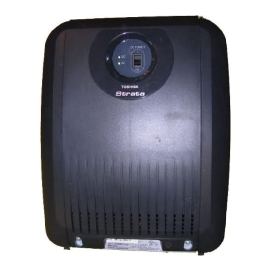
50Hz DC OUT 1.0A -27V1 -27V2 AC IN -27V3 -27V4 AC IN TOSHIBA CORPORATION TOSHIBA CORPORATION P.F. POWER RESET MADE IN INDONESIA BASE 5002 CAUTION: This unit may have more than one power cord, up to seven power cords may be provided. -
Page 80: Cabinet Installation Considerations
Strata CTX670 Installation Cabinet Installation Considerations The Base (CHSUB672) and Expansion (CHSUE672) Cabinets can be wall or floor mounted. To make it easier to add cabinets (after the initial installation) when a customer needs to expand, install the Base Cabinet on top for wall-mount installations and on the bottom for floor-mount installations. The dimensions of the Base and Expansion Cabinets are: Height: Base Cabinet: 29.8cm (11 3/4 inches) Height: Expansion Cabinet/Remote Expansion Cabinet: 25.4cm (10 inches) -
Page 81: Check The -24 Volt Circuit Breakers
Strata CTX670 Installation Note The backplane FG wires are not safety grounds: they are required for proper system Exchange line operation. 4. Plug the Back Plane DC OUT cable plug into the DC OUT connector on the power supply. (The plug has a guide key on it to ensure that it is plugged in correctly.) 5. -
Page 82: Check The Power Factor Indicator And Reset Button
Strata CTX670 Installation Check the Power Factor Indicator and Reset Button The front panel of BPSU672A provides a Power Factor LED and Reset button. If the cabinet power factor is exceeded by overload of PCBs, the PF LED will turn on. If the PF LED indicator turns on, press the PF reset button with a pointed tool or pencil. - Page 83 Strata CTX670 Installation Back Plane DC Voltage Connector Back Plane DC Voltage Cable/Plug Cabinet Support Post DC OUT -27V1 -27V2 BATT -27V3 -27V4 AC IN P.F. POWER RESET BASE B101 B102 S101 S102 S103 S104 S105 S106 S107 S108 5039 Wire Clamp Green/Green yellow wire fastened with FG Screw...
-
Page 84: Step 2: Mount Cabinets
The floor mounting description begins Page 3-27. Note Toshiba recommends installing cabinets (see Figures 3-4~3-10) from the top down, Base Cabinet on top, first Expansion Cabinet below it, second cabinet below that, etc. -
Page 85: Wall Mounting Expansion Cabinets
Strata CTX670 Installation 14. Reinstall the front cover, top cover, and side covers onto the cabinet. Wall Mounting Expansion Cabinets 1. Remove the front, back, and side covers from the Expansion Cabinets. Note The two screws on the front cover and the two screws on each side cover should be loosened just enough to slide the covers off. - Page 86 Strata CTX670 Installation Locating Parts Plaster Board Wall 9cm (3/4") Plywood Backboard #12 X 2" (or long enough to secure to the wall stud) Wood Screws Use as many as necessary to secure plywood backboard. Dealer Supplied #12 X 1.25" Wood Screws (4 Screws Per Cabinet)
- Page 87 Strata CTX670 Installation Top Cover (Base Cabinet Only) Back Cover Right Side Cover Remove four screws to remove back cover Loosen two screws to remove the side cover 5041 (right and left covers) Top Cover (Base Cabinet Only) Loosen four screws to remove the top cover.
- Page 88 Strata CTX670 Installation Marking Hole I N . Trace Upper Arch 9 . 9 I N . Back Cover 1459 Figure 3-6 CTX670 Back Cover Mounting Holes Hang cabinet on back cover then slide to right. Hanger Back Cover Hanger Hole Back Cover Mounting Strip After mounting...
- Page 89 Strata CTX670 Installation B101 B102 S101 S102 S103 B101 B102 B101 S102 S103 S104 S105 S106 S107 S108 DC OUT -24V1 S104 S105 S106 S107 S108 -24V2 BATT -24V3 -24V4 AC IN P.F. POWER RESET BASE B101 B102 S101 S102 S103 S104 S105...
-
Page 90: Step 3: Install Data Cables
Strata CTX670 Installation Step 3: Install Data Cables 1. After mounting the CTX670 cabinets, install the data cables. Then, install the bonding plate per Figure 3-9. Cab 2 Cable Left Side Base Cabinet Cable Guard Screw Cable Guard PCB Cable Data Cables Expansion Cabinet... - Page 91 Strata CTX670 Installation 2. Wrap the cables in with the mesh tie. The purpose of the wrap is to shield the cables from EMI/RFI effects. See Figure 3-10. Front Cable Shield (B50MT) Part No. B50MT comes with the Base Cabinet. It must be ordered separately for each Remote Cabinet pair.
-
Page 92: Step 4: Ground The System
Strata CTX670 Installation Step 4: Ground the System The system requires a solid earth ground for proper operation and safety. The AC power cord(s) already contains a conductor for the “third wire ground” provided by the commercial power outlet (see Figure 3-11, for grounding points “A”... - Page 93 Strata CTX670 Installation The Single Point Ground must always be connected to the Base Cabinet Power Supply FG Screw FG (Frame Ground) Screws Power Supply “B” Point “B” is always on the Base Cabinet. BMEP Base Cabinet Cabinet Motherboard Insulated Ground Wire “B” Note: AWG #6 Wire The impedance of the link...
-
Page 94: Step 5: Install Ac Power Components
240VAC is required for six or seven cabinet systems. Toshiba recommends that a dedicated AC service panel be used for the CTX670. AC outlets must be dedicated to CTX670 use, fused, and grounded. Equipment unrelated to the CTX670 must not be connected to the circuit or service panel dedicated to the CTX670. - Page 95 Strata CTX670 Installation Mains Input Cabinet Right-Side-Panel Power Strip (BPSB240) BPSB240 BPSB240 DK Mains CON-4 Screws provided with Power Strip 5219 SEVEN CABINET To AC Outlet INSTALLATIONS Cabinet Bonding Plate CAB 7 DK Mains CON-4 FIVE CABINET INSTALLATIONS CAB 6 FOUR CABINET INSTALLATIONS CAB 5...
- Page 96 Strata CTX670 Installation Right Side AC Power Cables Front Bonding Connection Plates (Required for all wall mounted expansion cabinets on both right and left sides) In the UK mains to 240VAC power supply cord is Connection box is used shipped with each cabinet. 5233 All Power Strip cords are 2.75m (9ft) long...
-
Page 97: Step 6: Install Reserve Power
Strata CTX670 Installation Step 6: Install Reserve Power Two or four customer-supplied, 12VDC batteries (80 amp hours maximum) can be connected to the system as a power failure backup. In the event of a power failure, the system automatically switches over to battery power without any interruption to existing calls or other normal system functions. -
Page 98: Reserve Battery Cabinet Components/Cables
Strata CTX670 Installation Reserve Battery Cabinet Components/Cables The part names and descriptions of the reserve battery cabinet components and cables are shown in Table 3-2. Table 3-2 Reserve Battery Cabinet Components/Cables Option Description A three-meter battery cable used to connect reserve power batteries to the system power supply when the system has less than three cabinets. -
Page 99: Reserve Power For Three Or More Cabinets (Wall Mount)
Strata CTX670 Installation Reserve Power for Three or More Cabinets (Wall Mount) 1. Install the Battery Distribution Box (BBDB) to the bottom cabinet (see Fig 3-20). The BCCB is not required for wall mount systems. 2. Connect two Cable “C” jumper wires from the positive terminal of one 12VDC battery to the negative terminal of the second 12VDC batter, per Figure 3-14 (Cable “C”... - Page 100 Strata CTX670 Installation 2-Batteries/1~7 Cabinets (with BBDB) BBTC1A-2M Cable consists of two (6.5 ft.) wires. White Wire 12 Volt Cabinet 2-Batteries/1-Cabinet (without BBDB) Batteries 15A Fuse (2 each) 80 AMP/ (only) Base Cabinet 12 Volt HR Each Batteries BPSU672 BATT Cabinet 80 AMP/ “C”...
-
Page 101: Cabinet Floor Mounting
Strata CTX670 Installation Cabinet Floor Mounting The part numbers and descriptions of the floor mounting hardware are shown in Table 3-3. Table 3-3 Floor Mount Hardware Option Description Floor mount fixture kit is required when floor mounting two or more CTX670 cabinets. Provides two metal stands for mounting any number of CTX670 cabinets on floor. - Page 102 Strata CTX670 Installation Floor Mounting Three or More Cabinets This section shows you how to mount three or more cabinets to a concrete, wood or computer room floor. Use the General Steps for all of these methods first, then the specific steps that follow for each method.
- Page 103 Strata CTX670 Installation Top Cabinet Wall Securing Brackets (RWBF) (Left and Right Side) Front (2) Back (2) Mounting Mouting Screws Provided Screws with BFIF Kit Provided with BFIF Kit Base Cabinet Third Cabinet Wall (bottom) Securing Bracket (RWBF) (Left and right side) BFIF Bottom Wall Mounting...
- Page 104 Strata CTX670 Installation RWBF RWBF RWBF RWBFs are used on left and RWBF right sides, wherever indicated RWBF “A” Front two screws, left RWBF and right sides RWBF RWBF RWBF RWBF “B” Back two screws, left and right sides RWBF RWBF RWBF RWBF...
- Page 105 Strata CTX670 Installation Bolt Cabinets to Wooden Floor 1. Mount the CTX670 Base Cabinet on Floor Mount Fixtures (BFIF). See Figures 3-15 3-16. Base 2. Position the Base Cabinet at the selected Cabinet installation location. BFIF 3. Mark the floor where holes will be drilled. (Floor Move the Base Cabinet prior to drilling.
- Page 106 Strata CTX670 Installation 13. Use a hack saw to cut the threaded rods at a height of approximately 3.8cm (1.5”) above the floor tile. 14. Move the Base Cabinet into position over the threaded rods. 15. Secure the Base Cabinet to the floor using flat washers, lock washer, and hex nuts on each threaded rod.Mount Cabinets to Computer Room Floor (Unbolted).
- Page 107 Strata CTX670 Installation Strata Up to 7 Cabinets Bottom Cabinet (Wall Mount) Second from Bottom Cabinet (Floor Mount) MAINS CON4 Power Strips Cable from BCCB BBTCIA-2M BBDB1A Battery Distribution BBDB1A Battery Distribution Box BBTC2A-2M To BPSU672A Power Seven Cables Supply "BATT" Jack Supplied with BBDB BCCB120 or 240...
- Page 108 Strata CTX670 Installation BCCB120 (top view) 3 outlets NEMA:5-15R Fused: 250VAC/15A F1~F4 Battery Rated: 125VAC/15A Fuses 250VAC/15A BCCB240 (top view) 2 outlets To BBDB NEMA:6-20R Battery Distribution Box Not Fused Rated: 250VAC/20A BCCB BATT Battery Wire Specifications AC Wire #10 AWG minimum (2 pairs) Specifications: 42A max.
-
Page 109: Reserve Power/Ac Wiring For Three Or More Cabinets (Floor Mount)
Strata CTX670 Installation Reserve Power/AC Wiring for Three or More Cabinets (Floor Mount) To connect reserve power to floor-mounted systems with three or more cabinets See Fig 3-13 and follow these steps: 1. Make sure that the Conduit Connection Box is installed on the bottom base cabinet (see Figure 3-20). -
Page 110: Pcb Installation Considerations
Strata CTX670 Installation PCB Installation Considerations The Base Cabinet has ten slots. The first two slots, labelled “B101” and “B102” are reserved for the common control unit and future feature upgrades. The next eight slots (labelled “S101” ~“S108”) are universal and capable of hosting any of the station, line, and option interface PCBs compatible with the CTX670 systems. - Page 111 Strata CTX670 Installation 1. Set the battery jumper, “BATT,” on the BBCU PCB to the “On” position. 2. On the BBCU, make sure the Mu/A jumper plug is set to the A position (U.K.). 3. Before you install the BBMS, make sure the “ATTACHED BBMS” jumper is set to “NO.” 4.
- Page 112 Strata CTX670 Installation Network Interface RJ45 Set the jumper to "YES" only after installing the BBMS. MU Law for U.S. & Canada. For UK & European BBMS BBMS1A Memory use set to A Law. Module 5254 Figure 3-22 BBCU Processor PCB Be careful installing the BBMS (Figure 3-23).
- Page 113 Strata CTX670 Installation BEXS1A BEXS1A 5656 BECU1A 5667 BECU1A Figure 3-24 Installing BEXS onto BECU Figure 3-25 Installing BSIS onto BECU BEXS1A Serial Port Pins: RJ11 ( 6-pin jack ) BECU1A 5416 Figure 3-26 BECU with BEXS and BSIS 3-39 Strata CTX I&M September 2002...
- Page 114 Strata CTX670 Installation Ribbon Cables Built-in Modem (33.6 kbps, v.34 WinA dmin P C / S erver) Processor Heart Beat LED (0.4 seconds on/0.4 seconds off.) Smart Media Access Status LED Smart Media Card Socket (Smart Media card slides in, gold BS IS S erial P orts contacts face right, notched corner down) (R J 11, 6-pin modular)
- Page 115 Strata CTX670 Installation Avoid touching the connectors and protect the card from dirt, dust and liquids. Toshiba recommends backing up important data stored on the card. Table 3-4 BECU Controls, Indicators, and Interface Connectors Control/Indicator/Connector Type of Component Description VR901 Trim potentiometer Adjusts volume for MOH/BGM sources.
-
Page 116: Remote Expansion Cabinet Unit
Strata CTX670 Installation Remote Expansion Cabinet Unit The RRCU1A PCB enables a Local CTX Cabinets CTX670 Expansion Cabinet to be located up to three kilometers from its Base Cabinet. One RRCU1A connects to up to two ribbon-type Data Cables and applies the inter- cabinet signal to a fibre-optic pair. -
Page 117: Remote Cabinet Installation Instructions
Strata CTX670 Installation Remote Cabinet Installation Instructions All instructions apply to both the Base Cabinet and the Remote Expansion Cabinet except where specifically noted. 1. Install cabinets according to the instructions given at the beginning of this chapter. Pay particular attention to wiring and grounding instructions given for Remote Expansion Cabinets. - Page 118 Strata CTX670 Installation When installing the RRCU, be sure to put the card in the slot before attaching the data Important! cables. Detach the data cable before removing an RRCU1A. Failure to do so may cause interference with other data highways. 6.
- Page 119 Strata CTX670 Installation 8. Connect the fibre optic cables Pass the fibre optic cable through the protective tube. Route the tube through the clamp attached to the inner cabinet wall and secure the clamp Attach fibre to the SC connectors on the ROMS1A daughterboard. The TX side of the Master connects to the RX side of the slave.
- Page 120 Strata CTX670 Installation -24v PFT-CONTROL RDER SYCF SYCS Optical Module 4379 TX Side RX Side Remove Rubber Cap to plug in Fibre Optic Plastic Cable Fibre Optic Cable CAUTION! Inserting the fibre connector at an angle or too forcefully can cause damage.
-
Page 121: Status Indicators
Strata CTX670 Installation The fibre connection must conform to both the Optical Budget and Fibre Length specifications. It is possible to have a fibre connection longer than 3 km (1.86 miles) with less than 9 dB of loss; however, the CTX670 Remote Expansion Cabinet is sensitive to signal delay and cannot be guaranteed to operate at distances greater than 3 km (1.86 miles). -
Page 122: Monitor Port Communication Parameters
PC with communication software - such as ProComm™ Monitor jack PC DB9 or DB25 Com port Dealer-supplied 6-wire telephone modular cord (cross-pinned) Toshiba PPTC9 or PPTC25F 4439 Monitor jack (RJ12) pin numbering Figure 3-34 RRCU1A Monitor Jack 3-48 Strata CTX I&M September 2002... -
Page 123: Chapter 4 - Pcb Installation
PCB Installation This chapter contains information on Printed Circuit Boards (PCBs) which can be used in the cabinet slots of the Strata CTX systems. Prior to PCB installation, the power supply must be tested and the ground checked. Note PCB Chapter Layout Each PCB outline begins with the PCB’s designation and title (the outline appears in the chapter in alphabetical order by designation). -
Page 124: Pcb Hardware/Software Options
PCB Installation PCB Hardware/Software Options PCBs can be configured for a variety of hardware and software options. Hardware options are defined as either internal (generally related to optional PCB subassemblies) or external (related to connection of peripheral equipment, such as background music, voice mail, etc.). Hardware and software options for each PCB are identified in the individual PCB installation procedures in this chapter. -
Page 125: Adku Hardware Options
ADKU – Digital Telephone Interface Unit Circuits per PCB: eight digital telephone circuits Interfaces with: all Toshiba digital telephones (DDCB, DSS, ADM, BPCI) Older Version(s): none ADKU Hardware Options The ADKU digital telephone interface unit only works with the CTX100. Refer to Chapter 7 –... - Page 126 PCB Installation The figure below shows where to install the ASTU on the CTX100 Base cabinet. Table 4-3 shows the interface connectors. 4 Holes ASTU position Connecter from Base Cabinet This connector of 5 cables is for power Hole for FG wire (FG1). The earthing lead from the ASTU must be terminated here.
-
Page 127: Bdku Hardware Options
BDKU/BDKS – Digital Telephone Interface Unit Circuits per PCB: eight digital telephone circuits (plus eight more with the BDKS PCB) Interfaces with: all Toshiba digital telephones (DDCB, DSS, ADM, BPCI) Older Version(s): none BDKU Hardware Options BDKU can be equipped with a BDKS piggyback PCB to provide a total of 16 circuits. Refer to Chapter 7 –... - Page 128 PCB Installation J 30 J 20 P 20 P 30 S ee P 2 " S etting" below. J 41 J 40 Optional BDK S , adds eight more DK T ports. B D K U 1 A V . 1 P 40 5498 Figure 4-3...
-
Page 129: Biou Installation
PCB Installation BIOU – Option Interface Units Circuits per PCB: (see interfaces) Interfaces with: three music-on-hold sources, system page and control relays Older Version(s): none The BIOU provides a Paging Output (amplified and non-amplified), four zone paging relays, three Music-on-hold (MOH) interfaces and four control relays (Night Transfer, Night Bell and Background Music (BGM) mute). - Page 130 PCB Installation Table 4-5 BIOU Controls, Indicators, and Connectors Control/Indicator/Connector Type of Component Description SW600 Page Output Switch SP0=600 ohms. SP1 = 3-watt amp. J1, J2, J3 RCA jack for connecting Interface connector for MOH/BGM source 1, 2, MOH/BGM source or 3.
-
Page 131: Bvpu Configuration
BVPU PC with maintenance console software Monitor jack PC DB9 or DB25 Com port Dealer-supplied 6-wire telephone Toshiba PPTC9 or modular cord PPTC25F (cross-pinned) Call-monitor jack (RJ12) pin numbering 5243 Figure 4-5 BVPU Monitor Jack Strata CTX I&M September 2002... - Page 132 PCB Installation Table 4-6 BVPU Controls, Indicators, and Connectors Control/Indicator/Connector Type of Component Description Serial Port RS-232C maintenance connection LAN Connector RJ45 10BaseT ethernet connection DIP Switch Unused. All switches = Off LED 1 Green LED On = Tie trunk 4 active LED 2 Green LED On = Tie trunk 3 active...
-
Page 133: Pdku2 Hardware Options
PCB Installation PDKU2 – Digital Telephone Interface Unit Circuits per PCB: eight digital telephone circuits Interfaces with: digital telephones (with or w/o ADM) (See Notes under Hardware Options)DDSS console (circuit 8 only) DKT2001 single line digital telephones Older Version(s): None PDKU2 Hardware Options PDKU2 does not have to be configured for any option. -
Page 134: R48S -48 Volt Supply Installation (Internal Option)
PCB Installation RSTU3 – Standard Telephone Interface Unit Circuits per PCB: eight standard telephone circuits Interfaces with: standard telephones voice mail ports off-premises stations other similar devices alternate BGM sources auto attendant digital announcer message waiting lamp Older Version(s): RSTU1–80-VRMS sine wave ring generator, optional R48S unit increases the loop voltage from -24VDC to -48VDC, extending the loop length (including the resistance of the phones from 600 ohms to 1200 ohms. -
Page 135: External Options
PCB Installation External Options W1 Ring Generator Switch Configuration (PSTU1 and PSTU2) On the PSTU1 or PSTU2, ensure the W1 switch is set to the “H” (190V P-P) position for initial installation. The “L” (130V P-P) position is used if devices connected to the PSTU1 or PSTU2 experience ring trip. - Page 136 PCB Installation MW-Mode Mu A CON NOR Optional SRSS Subunit 50-Pin Amphenol Connector (Female) Backplane Connector 5896 Figure 4-9 RSTU3 Controls and Interface Connectors 50-Pin Amphenol Connector (Female) Backplane Connector P7 UP 5809 Optional SSTU Subunit R48S R48S Installed Installed on RSTU1 on RSTU2 Figure 4-10...
-
Page 137: Rcos Installation (Internal Option)
PCB Installation RCOU3F, RCOS3F – Four-Circuit Loop Start Exchange Line Interface Unit Circuits per PCB: four loop start Exchange line circuits Interfaces with: loop start lines Older Version(s): PCOU2F The RCOU3F and RCOU provide ring detection, dial outpulsing, and hold circuitry. Each RCOU line can be programmed for DTMF or dial pulse signalling and has surge absorbers for secondary protection. - Page 138 PCB Installation Table 4-8 RCOS3F Controls, Indicators, and Connectors Control/Indicator/Connector Type of Component Description Exchange line circuit 5~8 Red LED Lights to indicate that line circuit is in operation. indicators (Exchange line indicator will not light unless RCOU is connected to a Exchange line). J3 connector Modular connector Interface connector for Exchange line circuits 5 and 6.
-
Page 139: Rcou Installation
PCB Installation Exchange Line LEDs Exchange Line Modular Jack Circuits 3 and 4 Exchange Line Modular Jack Circuits 1 and 2 5811 Figure 4-12 RCOS PCB RCOU Installation Note The decibel (dB) Pad switches SW101, SW201, SW301, and SW401 control excessive loudness resulting from close proximity to an Exchange Line or PBX telephone office by providing a -3 dB signal level drop to, or from, the PBX or Exchange Line when set to the 3 position. - Page 140 PCB Installation Table 4-9 RCOU3F Controls, Indicators, and Connectors Control/Indicator/Connector Type of Component Description Exchange line circuit 1~4 Red LED Lights to indicate that line circuit is in operation. indicators (Exchange line indicator will not light unless RCOU is connected to a Exchange line). J1 connector Modular connector Interface connector for Exchange line circuits 1...
- Page 141 PCB Installation RCOS Connectors Backplane Connector 5810 RCOS Connectors Figure 4-14 RCOU PCB Table 4-10 PCOU2 Controls, Indicators, and Connectors Control/Indicator/Connector Type of Component Description Exchange line circuit 1 CD112 Red LED Lights to indicate that line circuit is in operation. Exchange line circuit 2 CD212 Exchange line indicator will not light unless PCOU is Exchange line circuit 3 CD312...
- Page 142 PCB Installation RCOU Connectors Red LEDs 5812 RCOU Connectors Figure 4-15 PCOU2 PCB 4-20 Strata CTX I&M September 2002...
-
Page 143: Remu2A - Tie Line Unit
PCB Installation REMU2A – Tie Line Unit Circuits per PCB: four Tie line circuits Interfaces with: E&M Tie lines 2- or 4-wire transmission Older Version(s): PEMU The REMU2A has four decibel (dB) Pad switches which can be set to reduce excessive loudness resulting from close proximity to an Exchange Line or PBX by providing a -3 dB signal level drop to the PBX or Exchange Line. - Page 144 PCB Installation Table 4-11 REMU2A and REMU1A Controls, Indicators, and Connectors Control/Indicator/Connector Type of Component Description Tie trunk circuits 1~4 (CD102, 202, Red LED Lights to indicate that Tie line is in operation. 302, and 402) E&M Tie trunk connector circuits Modular connector Interface connector for E&M Tie line circuit.
- Page 145 PCB Installation Exchange Line LEDs E48S1A P402 P405 P102 P202 P302 TYP1/BATT TYP2/GND TYP1/2 TYP1/BATT TYP2/GND P305 TYP1/2 TYP1/BATT TYP2/GND P205 TYP1/2 TYP1/BATT TYP2/GND P105 TYP1/2 Backplane Connecto REMU2A 5905 PAD switch Figure 4-16 REMU2A PCB LEDs Backplane Connector REMU 5814 Figure 4-17 REMU PCB...
- Page 146 PCB Installation Table 4-12 PEMU Controls, Indicators, and Connectors Control/Indicator/Connector Type of Component Description Tie trunk circuit 1~4 (CD102, 202, Red LED Lights to indicate that Tie line is in operation. 302, and 402) E&M Tie line connector J101, 201, Modular connector Interface connector for E&M Tie line circuit.
-
Page 147: Pacu - Ac15 Tie Line Unit
PCB Installation PACU - AC15 Tie Line Unit System: Strata CT and CTX Circuits per PCB: four AC15 tie lines Interfaces with: AC15 ‘type A’ circuits Older Version(s): PACU1 Each PACU Interface Unit decreases the maximum number of system exchange lines by four. Each PACU Interface Unit will support four AC15 ‘type A’... - Page 148 PCB Installation Table 4-13 PACU controls, indicators and connectors Type of Control/Indicator/Connector Description Component Tie Trunk Circuit 1~4 Red LED Lights to indicate status. (CD101,201, 301 and 401) LED ON = cct busy or faulty. LED OFF = cct idle or operational. PAD Jumper Wire Circuits 1~4 White Wire Jumper Enables a -3dB receive signal lexel...
-
Page 149: Chapter 5 - Isdn Interfaces
ISDN Interfaces This chapter covers information on the ISDN Primary Rate Interface (PRI) and Basic Rate Interfaces (BRI). PRI Overview For PRI services, the Strata CTX uses an RPTU PCB to connect to a Public Switched Telephone Network (PSTN) PRI line. The RPTU PCB is shown in Figure 5-1 on page 5-4. -
Page 150: Strata Ctx Isdn Reference Model
ISDN Interfaces Strata CTX ISDN Reference Model A block diagram of the Strata CTX ISDN PCBs and reference points is provided in Figure 5-1. Demarcation Point CTX (NT2) RSTU PDKU RBSU TE-1-S RPTU (TE) (NT1) (Voice or Data) RBSU/RBSS (NTs (P-MP) TA-S Telco-... -
Page 151: Rptu Interface Unit
ISDN Interfaces RPTU Interface Unit Circuits per PCB: 30 channels Interfaces with: ISDN PRI Older Version(s): none The RPTU provides 30 channels for ISDN PRI service. The RPTU’s LEDs indicate a continuous status of its operation (see Figure 5-3 Table 5-2 on page 5-5). - Page 152 ISDN Interfaces Table 5-1 RPTU Switches, Jumpers, and Connectors Switches/Jumpers/Connector Description SW2 (Reset switch) Resets or initialises the RPTU firmware. Press this switch to correct an out-of-service condition, or just prior to connecting to the Network PRI. J1 8-pin Modular Connector (RJ45) Connects the RPTU to the CSU/network PRI ISDN line.
- Page 153 ISDN Interfaces Reset Switch (resets the software) Not Used RS-232C Connector FSYC for Call-Data Monitor (RJ-12) LEDs RJ-45 8-pin (shielded) Modular Connector (to CSU) 2747 Figure 5-3 RPTU LEDs and Connectors Table 5-2 LED Functions Functions Frame Synchronisation FSYC On:Frame alignment is lost. Off:Frame alignment is working properly.
-
Page 154: Cabling
Toshiba will ship a 5 metre (16.5ft) shielded patch cord terminated with BS EN28877 connectors with each RPTUIF. Cable Installation The RPTU PCB is shipped with a Toshiba RPRI cable kit for connection of the RPTU to a CSU. Install the kit as shown in Figure 5-5. - Page 155 ISDN Interfaces Ferrite Core Install the Ferrite core provided with the RPRI cable kit as shown in Figure 5-5. This core is needed to comply with EU requirements. RPTU Side View ISDN PRI Jack CAT5 Shielded Cable Tie Wrap Ferrite Core 2754 Note: The Ferrite core must be as close as possible to the RPTU.
- Page 156 ISDN Interfaces C onnec ting two R P T U2 P C Bs bac k-to-bac k for QS IG Networking QS IG C ross-P inned, R J 45 Modular C ord P in P in S trata C T X S trata C T X R P T U2 R P T U2...
-
Page 157: Rbsu/Rbss Interface Units
ISDN (TE-1 or TA) devices. The S point of the RBSU/ RBSS supports the Toshiba Strata CTX passive bus, also known as point-to-multipoint connection. The terminal-side (S-point) of the RBSU/RBSS BRI circuit can have parallel connections of up to two TE-1s or TAs maximum. -
Page 158: Capacity And Cabinet Slot Information
ISDN Interfaces When multiple TE-1 and TA devices are installed on a single RBSU/RBSS BRI circuit, the devices must share, or contend for, that circuit’s two B-channels. That is to say, a maximum of two simultaneous voice and/or data calls are allowed between both devices connected to the same BRI circuit. -
Page 159: Rbsu/Rbss Installation
ISDN Interfaces RJ45 Pin Nos. on RBSU RBSU or RBSS NT circuit Pin 3 RX + Pin 3 R40S PS-1 Pin 6 RX - Pin 6 TE Device Power Power sink Pin 4 TX + Pin 4 Source Pin 5 TX - Pin 5 RJ45 Pin Nos. - Page 160 ISDN Interfaces RBSU1A RBSS 2788 contacts TB1 TB2 RBSU1A-CM V. 1 2789 Figure 5-10 RBSS PCB Figure 5-9 RBSU PCB Table 5-3 RBSU/RBSS Option Switches, Jumpers, and Connectors Circuit Type Option Circuit Type Description Switch SW 1 Push- Resets firmware on all circuits of RBSU/RBSS. button Drops calls off the RBSU/RBSS.
- Page 161 ISDN Interfaces Install the RBSS Step 3: If one or two additional BRI-NT circuits are required, install the RBSS (see Figure 5-11). Note 1. Align the four connectors carefully while observing the “UP” arrows on the REBS. 2. Plug the RBSS onto the RBSU. Install the R40S Step 4: Note...
-
Page 162: Modular Jack Pin Configurations
ISDN Interfaces Install RBSU/RBSS PCBs into Cabinet Step 5: After setting the switches and jumpers and installing the plug-on PCBs as described in the preceding paragraphs, the RBSU/RBSS PCBs can be installed in the appropriate cabinet slots. Refer to RBSU/ RBSS Capacity and Cabinet Slot Information on Figure 5-13. -
Page 163: Rbsu/Rbss Premise Wiring Guidelines
ISDN Interfaces jack pin configuration and communication parameters are the same as RPTU (see Figures 5-21, 5-24 and 5-25). For RBSU monitor jacks, see Figure 5-23 Figure 5-12 on page 5-15.) RBSU/RBSS Premise Wiring Guidelines Grounding Terminal Screws TB3 is a screw terminal that can be used to connect a ground wire to the RBSU PCB (see Figure 5-12 for the location). - Page 164 ISDN Interfaces will have the locking tab of the plug on one end, “up;” and on the other end, “down,” as shown in Figure 5-13. A cord of up to 10 meters connects the ISDN BRI RJ45 wall jack to the desktop TE-1 or TA RJ45 jack. Locking Tab 3039 Four-pair Wire...
-
Page 165: Connecting Rbsu To Network Side (Te-Mode)
ISDN Interfaces Strata CTX BRI Circuit EU Ferrite Core Requirement To ensure that the Strata CTX BRI circuit meets the EU requirements, it is necessary to run all wire connecting ISDN BRI circuits (TE and NT mode) through a Ferrite core. . RBSU or RBUU RBSS or RBUS ISDN... -
Page 166: Connecting Rbsu/Rbss Station Devices (Nt-Mode)
ISDN Interfaces In the U.K., the BRI line from the ISDN service provider is a two-wire U-type BRI line. This line connects to the RBSU TE circuit via a customer-provided NT1 as shown in Figure 5-15. The NT1 is necessary to convert the network BRI, two-wire, U interface to the RBSU BRI, four-wire, T interface. The connection between the NT1 and the RBSU TE circuit is a point-to-point connection, so the NT1 can connect to only one RBSU BRI TE circuit. - Page 167 ISDN Interfaces RJ45 RJ45 Pinout Pinout RBSU NT Circuit S-type, TE-1 or TA with 100-ohm TR or just a Insert 100-ohm 100-ohm terminating TR using RBSU resistor across each pair and RBSS on a RJ45 jack. option switches. 5434 BRI (four-wire) To local AC Power S-type, TE-1s or TAs without...
-
Page 168: Rbsu/Rbss Passive Bus Configurations
ISDN Interfaces RBSU/RBSS Passive Bus Configurations Wiring Point to point Maximum number of sockets =1 Maximum number of terminals connected = 1 400m (CW1308) / 800m (CW 1700 or 1750) Socket with terminating resistor Pin number 1 RBSU Unit Pin number 8 CT I&M fig 14 Grey RJ45 socket Figure 5-17... -
Page 169: Timing And Synchronisation
ISDN Interfaces Timing and Synchronisation In the Strata CTX, one PRI or BRI can be programmed to extract the Stratum clock signal. It uses the signal as the Strata CTX system Primary clock reference. The clock provider should be a reliable source, such as a network operator. -
Page 170: Pri/Bri Call Monitoring
ISDN Interfaces If the path is not synchronised to the Stratum – 1 clock source, calls connected through that path experience “slipping” or “jitter” in the digital voice or data path (channels). The unsynchronised signal produces a clicking or popping sound that is heard by the people connected through this path or causes data errors on data transmissions. -
Page 171: Call Monitor Output For Isdn
- such as ProComm™ Call-monitor jack PC DB9 or DB25 Com port Dealer-supplied 6-wire telephone modular cord Toshiba PPTC9 or (cross-pinned) PPTC25F Call-monitor jack (RJ12) pin numbering 4696 The RPTU and RBSU ISDN interface PCBs each have a call-monitor jack. The pin numbering Note and communication parameters are the same for each call-monitor jack. -
Page 172
ISDN Interfaces /*-------------------------*/ Copyright(C) 1997 TOSHIBA Corporation All rights reserved RPTU Ver.1G [Reset] /*-------------------------*/
00;00’016 Act. (F1) /*-------------------------*/ Copyright(C) 1997 TOSHIBA Corporation All rights reserved RPTU Ver.1G [Reset] /*-------------------------*/ 00;00’016 Act. (F1) 00;09’634 LOS (F3) 00;12’109 Act. (F1) /*-------------------------*/ Copyright(C) 1997... -
Page 173
ISDN Interfaces
01;14’446 Rx:[SAPI]00 C [TEI]000 [FRAME]RR P [N(R)]004 01;14’449 Tx :[SAPI]00 C [TEI]000 [FRAME]RR P [N(R)]002 01;14’456 Tx :[SAPI]00 R [TEI]000 [FRAME]RR F [N(R)]002 01;14’460 Rx:[SAPI]00 R [TEI]000 [FRAME]RR F [N(R)]004 01;19’450 Tx :[SAPI]00 C [TEI]000 [FRAME]INFO [N(S)]004 [N(R)]002 PD = Q.931(08) CR = 02 0003 MT = SETUP(05) -
Page 174: Bri Call Monitor
ISDN Interfaces BRI Call Monitor The call-monitor jack located on the RBSU enables you to use a PC or ASCII terminal to monitor the BRI, D-channel call setup, layer-2 and layer-3 data (refer to Figure 5-21 on page 5-23 for information about connecting the monitor jack). -
Page 175
ISDN Interfaces
07;40'993 Tx :[SAPI]00 R [TEI]113 [FRAME]RR F [N(R)]000 07;40'997 Rx:[SAPI]00 R [TEI]113 [FRAME]RR F [N(R)]000 07;41'000 Tx :[SAPI]00 R [TEI]113 [FRAME]RR F [N(R)]000 07;41'005 Rx:[SAPI]00 R [TEI]113 [FRAME]RR F [N(R)]000 07;41'168 Tx :[SAPI]00 C [TEI]102 [FRAME]RR P [N(R)]027 07;41'180 Rx:[SAPI]00 R [TEI]102 [FRAME]RR F [N(R)]025... - Page 176 ISDN Interfaces 5-28 Strata CTX I&M September 2002...
-
Page 177: Chapter 6 - Mdf Pcb Wiring
MDF PCB Wiring This chapter contains point-to-point wiring diagrams for connection of telephones, lines, peripheral equipment, and power supplies for the universal slot PCBs of the Strata CTX system. Wiring diagrams are divided into groups according to the PCB which provides the interface for, or controls the operation of, the associated equipment, as listed below: Stations ADKU, BDKU,... -
Page 178: Station Loop Lengths
MDF PCB Wiring Station Loop Lengths In a single site installation, the Base and optional Expansion Cabinets must be placed within the allowed maximum distance of each other as designated by Table 6-1. Table 6-1 Station Loop Lengths Maximum line length (CW1308 0.5) Mode 1 Pair plus 1 Pair... - Page 179 MDF PCB Wiring Table 6-2 Loop Limits for DKT3000-series Telephones Maximum line length (CW1308 0.5) Power Supply Unit Telephone/Device (PSU) or Battery 1 Pair plus 1 Pair 2 Pair Backup external power DKT3000/DKT3500-series or 1000 ft. (303m) DKT2000-series models DKT with BVSU or DVSU or Battery Backup 675 ft.
-
Page 180: Station Wiring Diagrams
MDF PCB Wiring Station Wiring Diagrams Building #1 Building #2 HESB PSTU Standard RSTU/RSTU2/ Telephone RSTU3/ RDSU/RSTS DDSS Digital Console Telephone Digital Telephone or Cordless Base Console Handset ADKU, BDKU/BDKS or PDKU Attendant BATI DDCB Console MDFB MDFB DDCB 5655 RPTU DDI &... -
Page 181: Adku And Bdku/Bdks Digital Station Wiring
MDF PCB Wiring ADKU and BDKU/BDKS Digital Station Wiring To ADKU or BDKU/BDKS Jacketed Twisted Pairs Station Cabling Bridging W/Female Connector CW1308 0.5 (1 or 2 pair. See Note 1.) Clips T1 (Voice/Data) W-BL (GND) R1 (Voice/Data) BL-W PT1 (Add. Power) (GND) PR1 (Add. -
Page 182: Pdku Digital Station Wiring
MDF PCB Wiring PDKU Digital Station Wiring To PDKU Station Cabling Jacketed Twisted Pairs Bridging W/Female Connector CW1308 0.5 (1 or 2 pair. See Note 1.) Clips T1 (Voice/Data) W-BL (GND) R1 (Voice/Data) BL-W PT1 (Add. Power) (GND) PR1 (Add. Power) W-GN GN-W Circuit 2... - Page 183 MDF PCB Wiring Screw To PDKU With Terminals KRONE Female Connector 237A W-BL BL-W Circuit 1 W-GN GN-W Used Circuit 2 W-BR 6 5 4 3 2 1 Door Phone A BR-W MDFB (Rear View) DDCB Circuit 3 R-BL Door Phone BL-R MDFB Modular...
- Page 184 MDF PCB Wiring MDF Block Number KSU Slot Number Device/Standard Port Intercom Colour Code Designation Telephone/Electronic Number Number Number Telephone Location W-Bl Bl-W PWR-A PWR-B W-Br PWR-A Br-W PWR-B R-Bl PWR-A Bl-R PWR-B PWR-A PWR-B R-Br Br-R PWR-A PWR-B Bk-Bl Bl-Bk Bk-O PWR-A...
-
Page 185: Digital Telephone Dss And Ddcb External Power Connection
MDF PCB Wiring Digital Telephone DSS and DDCB External Power Connection BDKU or PDKU Station Cabling Jacketed Twisted Pairs Connector Bridging CW1308 0.5 (1 Pair) Clips T1 (Voice/Data) W-BL (GND) R1 (Voice/Data) BL-W (Not Used) W-GN DC Output GN-W CKT 2 W-BR BR-W AC/DC External... - Page 186 MDF PCB Wiring MDF Block Number KSU Slot Number Colour Code Designation Intercom Device/Standard Telephone W-Bl Bl-W PRW-T PRW-R W-Br PRW-T Br-W PRW-R R-Bl PRW-T Bl-R PRW-R PRW-T ADKU, PRW-R BDKU R-Br Br-R PDKU PRW-T PRW-R Bk-Bl Bl-Bk Bk-O PRW-T O-Bk PRW-R Bk-G...
-
Page 187: Rstu Or Pstu Analogue Devices Wiring
MDF PCB Wiring RSTU or PSTU Analogue Devices Wiring To RSTU or PSTU w/Female Connector Bridging Jacketed Twisted Station Cable Clips CW1308 0.5 Tip 1 W-BL Ring 1 BL-W Not Used W-GN (See Notes) GN-W W-BR Not Used BR-W R-BL Not Used BL-R 6 5 4 3 2 1... - Page 188 MDF PCB Wiring MDF Block Number KSU Slot Number Port Intercom Colour Code Designation Device/Standard Telephone Location Number Number Number W-Bl Bl-W Not Used Not Used Indicate if separate BGM source. W-Br Not Used Br-W Not Used R-Bl Not Used Bl-R Not Used Not Used...
-
Page 189: Power Failure Cut Through (Dpft) Wiring Pin-Outs
MDF PCB Wiring Power Failure Cut Through (DPFT) Wiring Pin-outs Pair Colour Code Lead Designation Function PSTU/RSTU PCB Position W-BI TIP-TEL BI-W RING-TEL TIP-RSTU/RSTU/RDSU RING-PSTU/RSTU/RDSU TIP-TEL RING-TEL W-Br TIP-RSTU/RSTU/RDSU Br-W RING-PSTU/RSTU/RDSU TIP-TEL RING-TEL R-BI TIP-RSTU/RSTU/RDSU BI-R RING-PSTU/RSTU/RDSU TIP-TEL RING-TEL TIP-RSTU/RSTU/RDSU RING-PSTU/RSTU/RDSU R-Br TIP-TEL... - Page 190 MDF PCB Wiring Pair Colour Code Lead Designation Function PSTU/RSTU PCB Position W-BI TIP-EXCHANGE BI-W RING-EXCHANGE TIP-PCOU/RCOU RING-PCOU/RCOU TIP-EXCHANGE RING-EXCHANGE W-Br TIP-PCOU/RCOU Br-W RING-PCOU/RCOU TIP-EXCHANGE RING-EXCHANGE R-BI TIP-PCOU/RCOU BI-R RING-PCOU/RCOU TIP-EXCHANGE RING-EXCHANGE TIP-PCOU/RCOU RING-PCOU/RCOU R-Br TIP-EXCHANGE Br-R RING-EXCHANGE TIP-PCOU/RCOU RING-PCOU/RCOU Bk-BI TIP-EXCHANGE BI-Bk...
-
Page 191: Exchange Line Wiring Diagrams
MDF PCB Wiring Exchange Line Wiring Diagrams Network KRONE 237A PCOU Line LEDs Signal Ground (only required for Earth Recall in piggyback application Line 4 Line 3 Line 2 Line 1 Modular Socket for Power Fail Connection Pins 2 & 4 provide 24 VDC (2 = -24 &... -
Page 192: Rcou/Rcos Wiring
MDF PCB Wiring RCOU/RCOS Wiring Network Bridging Clips Telco-provided Modular Block, 625-type or Equivalent 6 5 4 3 2 1 2 3 4 5 Modular Cord 7 + 8 Same 3 + 4 Same 5 + 6 Same 1 + 2 Network Jack: RJ14C FIC: 02LS2 66M150 Split Block... - Page 193 MDF PCB Wiring Exchange PCB Type and Exchange PCB Type and Exchange PCB Type and MDF Block MDF Block MDF Block Line Cabinet Slot Line Cabinet Slot Line Cabinet Slot Number Number Number Number Number Number Number Number Number Figure 6-14 Exchange Line (RCOU/RCOS, PEMU, REMU) MDF Cross Connect Record 6-17 Strata CTX I&M September 2002...
- Page 194 MDF PCB Wiring REMU Same Pinout Line #4 To Network Jack as Line #1 Same Pinout Line #3 To Network Jack as Line #1 Same Pinout Line #2 To Network Jack as Line #1 LEAD — PIN # — — —...
-
Page 195: Pemu Wiring
MDF PCB Wiring PEMU Wiring KRONE Network 237A PEMU 2-Wire 2 WIRE CTX Wire Pair Functions CTX, Transmit CTX, Receive Signalling E1, M1 1587 Figure 6-16 MDF Wiring/2-Wire Tie Line to PEMU 6-19 Strata CTX I&M September 2002... - Page 196 MDF PCB Wiring KRONE Network 237A PEMU 4-Wire 4 WIRE CTX Wire Pair Functions CTX, Transmit T1, R1 CTX, Receive C1, D1 Signalling E1, M1 1588 Figure 6-18 MDF Wiring/4-Wire Tie Line to PEMU 6-20 Strata CTX I&M September 2002...
- Page 197 MDF PCB Wiring KRONE Network 237A PACU CTX Wire Pair Functions CTX, Transmit TT1, TR1 CTX, Receive RT1, RR1 1589 Figure 6-19 MDF Wiring AC15 Tie Lines to PACU 6-21 Strata CTX I&M September 2002...
-
Page 198: Option Interface Pcb Wiring Diagram
MDF PCB Wiring Option Interface PCB Wiring Diagram This section covers wiring for the option interface PCB, the BIOU, which enables external paging, Night Bell, Night Transfer, Door Lock and BGM mute control. For more information and connection diagrams, see “External Page with BIOU Interface”... -
Page 199: Chapter 7 - Station Apparatus
This chapter provides instructions on how to connect telephones to the Strata CTX systems and how to configure and upgrade them for optional features. The Strata CTX systems can support Toshiba corded and cordless digital telephones, as well as most standard telephones provided by other suppliers. The digital telephone information in this chapter applies to the 3000/3500*-series and 2000/2500*-series telephones that connect to the PDKU, ADKU or BDKU/BDKS interface. -
Page 200: 3000/3500-Series Digital Telephones
Station Apparatus 3000/3500-series Digital Telephones The 3000/3500-series digital telephone (DKT) models consist of: 1. DKT3010-S (10-button speakerphone model which enables users to make and receive outside and internal calls without lifting the handset.) 2. DKT3020-S (20-button speakerphone model which enables users to make and receive outside and internal calls without lifting the handset.) 3. -
Page 201: Telephone Installation
Station Apparatus Telephone Installation Digital Telephone System Connection The following provides information on how to connect all 3000/3500-series DKTs to the Strata CTX systems. 3000/3500-series DKTs can be connected to the BDKU/BDKS and/or the PDKU interface PCB. To obtain all capabiltities, the DKT3000/3500-series telephone must be connected to the BDKU/ BDKS. -
Page 202: 3000/3500-Series Telephone Option Pcbs
Station Apparatus When installing the station cable, do not run the cables parallel if they are within CAUTION! three feet of an AC power line. AC power lines should be crossed at right (90 ° angles only. In particular, avoid running station wire pairs near devices that generate electrical noise, such as neon or fluorescent light fixtures. - Page 203 Station Apparatus Some of the option PCBs are compatible, meaning that more than one option can be added to a telephone. The following table shows which options are compatible. Table 7-3 Station Option Interface PCB Compatibility BHEU/ Item BPCI BVSU HHEU BPCI BHEU/HHEU...
-
Page 204: Telephone Speaker Off-Hook Call Announce Upgrade (Bvsu)
Station Apparatus Telephone Speaker Off-hook Call Announce Upgrade (BVSU) To receive Speaker Off-hook Call Announce (OCA) calls over the digital telephone speaker, a digital telephone must be upgraded with a BVSU; the telephone making the call does not require a BVSU. Digital telephones do not require an additional wire pair to receive Speaker OCA call. - Page 205 Station Apparatus 6. Reinstall the telephone base and secure it with its four captive screws. F asten T elephone Base T o P C I/V S U T wo C onnec tors S c rews C aptive S c rews on T elephone (One in Each C orner) K noc k out for...
-
Page 206: Telephone Headset (Bheu) Upgrade
Station Apparatus Telephone Headset (BHEU) Upgrade The BHEU can be installed into the DKT3000/3500-series telephones to enable headset or external ringer use. For information on connecting the external ringer, refer to “Telephone External Ringer” on Page 8-17. The BHEU can also be installed into DKT3010 and DKT3020 telephones that have either a BVSU or BPCI installed. -
Page 207: Telephone Option Straps
Station Apparatus (P 3) HEU BHEU BV S U or BP C I (optional) Digital T elephone T op A ssembly R ed Wire Digital T elephone Base 5657 Figure 7-6 BHEU Installation Telephone Option Straps Certain option straps on the DKT3000/3500-series phones must be cut when installing carbon handsets, external power or headsets. - Page 208 Station Apparatus EX.P OWER W101 W101 W102 W102 EX.P OWER EX.P OWER W303 C A R BON W303 W301 C A R BON W302 C A R BON 5668 W301 5603 Figure 7-7 DKT3010, DKT3020 Strap and Figure 7-8 DKT3014 Strap and Connector Connector Locations Locations W101...
-
Page 209: Tapi And Simultaneous Voice And Data Upgrades For 3000/3500-Series Telephones (Bpci)
Station Apparatus TAPI and Simultaneous Voice and Data Upgrades for 3000/ 3500-series Telephones (BPCI) Digital telephones can be upgraded with a Personal Computer Interface (PCI) to provide desktop interface with the telephone and PC USB port. The PC connected to the BPCI can place telephone calls, receive Caller ID, ANI, and DNIS information. -
Page 210: 3000/3500-Series Telephone Settings
Station Apparatus 3000/3500-series Telephone Settings The button layout for the 3010- and 3020-series telephones are shown in Figure 7-12. The DKT3014, large LCD telephone has additional buttons for features and programming (see Figure 7-14). DK T 3020-S , DK T 3020-S D L C D (24 C harac ters by 2 lines) Mode... - Page 211 Station Apparatus (24 Character by 2 lines) Figure 7-13 DKT3512-SD/DKT3524-SD Button Telephones 7-13 Strata CTX I&M September 2002...
- Page 212 Station Apparatus P ush in to tilt L C D Mode F eature L C D P age S c roll (24 C harac ters by 8 lines) S oft K eys S oft K eys (F B 7) (F B 14) (F B 6) (F B 13) (F B 5)
- Page 213 Station Apparatus Spdial Line Flex Spkr Hold Cnf/Trn 5654 Figure 7-15 DKT3001 Buttons 7-15 Strata CTX I&M September 2002...
-
Page 214: Telephone Programming Mode A
Station Apparatus Telephone Programming Mode A The 3000/3500-series telephones enable you to set a number of features directly from the phone, including: Call Waiting Tone (On/Off), Flex Key, Msg Key, LCD contrast, Speakerphone/Microphone Room Noise Sensitivity (On/Off), and Country settings. “Telephone Programming Mode A” programs settings on a ROM chip inside the telephone. -
Page 215: Speakerphone/Microphone Sensitivity Adjustment
Station Apparatus Speakerphone/Microphone Sensitivity Adjustment When you are using the speakerphone, high ambient noise levels may cause the party you are talking with to be to cut off frequently. If this happens, follow these steps to lower the sensitivity of the microphone on a 3000/3500-series telephone. -
Page 216: Redial/Feature Button Activation/Deactivation (Dkt3001 Only)
Station Apparatus To turn DKT2000/2500 Mode On/Off Step 1: You must change the mode on DKT3000/3500 telephone before connecting a DKT2004- Important! CT or DKT2104-CT to the DKT3000/3500. Hold 1. On the DKT3000/3500 telephone, press (simultaneously). 2. Press FK13 3. Press on the DKT3014). -
Page 217: Test The Display On Large Lcd Telephones (Dkt3014-Sdl Only)
Station Apparatus Test the Display on Large LCD Telephones (DKT3014-SDL only) Hold 1. Press (simultaneously). Page 2. Press 3. Press . LCD screen is blank. 4. Press . Each segment shows three vertical lines, in all eight rows. 5. Press . -
Page 218: Digital Add-On Module Installation
The DADM provides 20 buttons that can be flexibly programmed for any telephone feature that is provided by the Strata CTX system. Install one or two DADM to a Toshiba digital telephone (only) (shown below). The digital telephone and the DADM must belong to the same series, i.e., 3000/3500- or... - Page 219 Station Apparatus 8. If required to achieve maximum distance, install two-pair house cable (or external power) and two-pair modular cord, supplied with DADM. (See Chapter 6 – MDF PCB Wiring.) 9. If a second DADM should be installed, connect P1 of the second DADM to P2 of the first DADM with the DADM connecting cable.
-
Page 220: Tilt Stands And Wall Mounting
Station Apparatus Tilt Stands and Wall Mounting This section explains how to attach desktop tilt stands to 3000/3500-series or 2000/2500-series digital DKTs or to a DSS console. Use Tilt Stand model “BTSD” (not BTSA) with a standalone DKT or DSS. To attach a Tilt Stand to a 3000/3500-series DKT or DSS 1. -
Page 221: Tilt Stand Installation With Add-On Modules
Station Apparatus Tilt Stand Installation with Add-on Modules This section explains how to attaching a tilt stand to a digital telephone with one or two ADMs. Follow the instructions for the appropriate number of ADMs. Use Tilt Stand models “BTSA” (not “BTSD”) for DKTs with one or two ADMs. - Page 222 Station Apparatus R elease Button To remove the base from the tilt stand: 1. P ush in lock release. 2. Open the tilt stand 90 degrees. 3. P ull the Base away from the stand to remove it. T ilt S tand Base 5475 F it T ilt Base onto T ilt S tand Bottom P egs...
-
Page 223: Tilt Stand For Dkt + 2 Adms
Station Apparatus Tilt Stand for DKT + 2 ADMs Use Tilt Stand models “BTSA” for DKTs with one or two ADMs. To attach a digital telephone with two ADMs to a Tilt Stand 1. Complete the steps under “To install DADMs” on Page 7-20. -
Page 224: Telephone Wall Mounting
Station Apparatus 5849 Figure 7-24 Tilt Stands in Raised Position for DKT and Two ADMs Telephone Wall Mounting This section explains how to mount digital telephones to a wall. See the manufacturer’s documentation for instructions on mounting standard phones. Notes Digital telephones equipped with BPCIs or PDIU-DI2s cannot be wall mounted. - Page 225 Station Apparatus 5. Connect the phone to the wall modular connector with a cord approximately four inches long (available at most telephone supply companies). 6. Route the cord into the hollow portion of the base. 7. Mount the phone on the wall mounting modular connector plate.
-
Page 226: Direct Station Selection (Dss) Console/System Connection
Station Apparatus Direct Station Selection (DSS) Console/System Connection The DSS console can be connected to a BDKU/BKDS or PDKU on any circuit. DSS consoles are associated with digital telephones via system programming. This section provides instructions on how to install the consoles. DSS Console Connections DSS consoles are connected to BDKU/BDKS or PDKU PCBs using standard twisted single-pair or two-pair jacketed telephone... -
Page 227: Standard Telephones
Station Apparatus Standard Telephones This section explains how to connect standard telephones to the Strata CTX670 system. Toshiba does not provide standard telephones. Whenever standard telephones are mentioned in this manual, it refers to 500- and 2500-type standard telephones. Before proceeding, see warning and caution notes in “Telephone Installation”... -
Page 228: Precautions
Before you read anything else, please observe the following: WARNING! Toshiba does not represent this unit to be waterproof. To reduce the risk of fire, electrical shock, or damage to the unit, do not expose this unit to rain or moisture. -
Page 229: Dkt2104-Ct
Station Apparatus DKT2104-CT The DKT2104-CT works with Strata CTX telephone systems and provides you with reliability, long life, and outstanding performance. Some of its features are: 900 MHz Digital Narrow Band technology 30 Simultaneous channels LCD that wraps using 2 lines, total of 32 characters Four displayed operation modes, including Message Waiting (MW) Hold, MSG (LCD icon), Cnf/Trn, and Mute buttons... -
Page 230: Telephone Cord Connection
Station Apparatus To mount on a wall 1. Select a wall location near a 120VAC outlet and within reach of the Strata CTX digital line connection. 2. Place the wall plate (shown at right) against the wall, and with a pencil, mark the position of the screws.With a punch tool, punch “starter”... -
Page 231: Cordless Telephone Connectors
Station Apparatus To connect the cordless telephone using the AC adapter 1. Plug the AC adapter cord into the AC adapter input jack on the base unit (see Figure 7-29). Use only the AC adapter supplied with your cordless digital telephone. CAUTION! Line in to Digital Telephone Circuit... -
Page 232: Handset Battery Pack Installation
Station Apparatus Attach/Remove Belt Clip to Handset (optional) To attach the belt clip to the handset 1. Snap the tabs of the belt clip into the notches on the sides of the handset. 2. Use the belt clip to attach the handset to your belt or pocket for convenient portability. To remove the belt clip 1. -
Page 233: Tips On Extending Battery Pack Life
Station Apparatus To charge the DKT2104-CT handset’s battery pack Important! Before using your handset, the battery must be continuously charged for 10 hours. 1. Place the handset in the Charger Unit (shown at right). 2. Ensure that charge 1 LED lights. If it does not, make sure that the AC adapter is plugged in and that the handset is making good contact with the Charger Unit. -
Page 234: 2000/2500-Series Telephones
Station Apparatus LCD Low Battery Indicator When the battery pack in the handset is low and needs to be charged you see this message on the display and the handset beeps. Table 7-7 shows symptoms. Table 7-7 Low Battery Symptoms On a Call... -
Page 235: Telephone Speaker Off-Hook Call Announce Upgrade (Dvsu)
Station Apparatus Telephone Speaker Off-hook Call Announce Upgrade (DVSU) To receive Speaker Off-hook Call Announce (OCA) calls over the digital telephone speaker, a 2000/ 2500-series digital telephone must be upgraded with a DVSU; the telephone making the call does not require a DVSU. -
Page 236: Hheu Installation
Station Apparatus Table 7-9 Mu Law Settings for DKT2010-S, 20-S, 10-SD, 20-SD 30 (default setting) 20 Mu (Mu Law countries) (A Law countries) Use for U.S. and Canada) SPF (default setting). Use for U.S. and Canada) Table 7-10 Mu Law Settings for the DKT2010-H 30 (default setting) 20 Mu (Mu Law countries) - Page 237 Station Apparatus 4. Connect the HESC-65A cable to P601 of the Feed Through To HESB HHEU (both HHEU1A versions and the HHEU2 for HESC-65(A) Cable Block have P601) if the Loud Ringing Bell option is required. Refer to Chapter 8 – Peripheral Installation HESB installation procedures.
- Page 238 Only digital telephones equipped with an HHEU2 can be wall mounted. The HHEU2 is identical to the V.4 HHEU1, except that the HHEU2 has longer wires to accommodate wall mounting. A Toshiba HESC-65A cable is required to connect the HHEU in a digital telephone to the HESB. 7-40...
-
Page 239: Carbon Headset/Handset Straps
Station Apparatus To adjust the volume of the HESB Loud Ringing Bell 1. Call the telephone connected to the HESB. 2. Adjust the volume control on the back of the HESB and the ring volume control on the telephone. Note TAPI and Simultaneous Voice and Data Upgrades (RPCI-DI or PDIU-DI2) for 2000/2500-series Telephones is not available on the Strata CTX. -
Page 240: Busy Override And Camp-On Ring Tone Over Handset/Headset Option
Station Apparatus Busy Override and Camp-on Ring Tone Over Handset/Headset Option Busy override and camp-on ring tones can be sent over the DKT handset or headset, in addition to the speaker. To send busy override/camp-on ring tones over the handset of the DKT2010-H model 1. -
Page 241: Dip Switches
Station Apparatus DIP Switches The DKT2000/2500 V.4 series telephones have DIP switches that enable use for the international market. The DIP switches are located underneath the flexible button key strip on the DKT2000/2500 V.4 series telephones (see Figure 7-37). On the DKT2001, the DIP switch is located on the base. LCD Display Handset DIP Switches... -
Page 242: Dkt2020-Fdsp Full-Duplex Speakerphone With External Microphone
Station Apparatus DKT2020-FDSP Full-Duplex Speakerphone with External Microphone Note Not available in the UK & Europe. The DKT2020-FDSP is designed to allow both parties of a speakerphone call to speak simultaneously. This eliminates “clipping” and enables true two-way conversation. However, when two parties are talking simultaneously, the performance is not as good as on a handset. - Page 243 Station Apparatus Good – provides full-duplex operation with the Internal or External Microphone. This is ideal for a small office with high echo. Normal – provides full-duplex operation with the Internal or External Microphone. This works well with an open office area, such as an office cubicle. Table 7-12 shows the switch positions for the three different settings.
- Page 244 Station Apparatus EXT MIC EXT MIC 5217 HIGH 5218 Figure 7-38 RFDM Plug on DKT2020-FDSP Figure 7-39 RFDM Unit Figure 7-40 External Microphone On/Off RFDM Unit (OFF Position) RFDM Unit (ON Position) 5352 RFDM Super Directional Microphone 5353 Figure 7-41 External Microphone Voice Pick-up Path 7-46 Strata CTX I&M September 2002...
- Page 245 Station Apparatus Speech Training Mode When the DKT2020-FDSP is used in speakerphone mode, it adjusts to both the telephone line’s and room’s acoustic properties. At the beginning of each speakerphone call, the echo canceller must perform Speech Training by evaluating both the FDSP user and the far-end user’s voice, background noise and line quality.
-
Page 246: Digital Single Line Telephone (Dkt2001 Only)
Station Apparatus To toggle full/half-duplex mode Press button 10 (see Figure 7-42) to turn full-duplex mode On or Off. Full-duplex mode: Button 10 LED Off. Half-duplex mode: Button 10 LED On. Notes Button 10 functions the same for Internal and/or External Microphone. If DIP switch 6 and 7, in Figure 12, are turned Off, the Full/half-duplex function of Button 10 is disabled. -
Page 247: Chapter 8 - Peripheral Installation
Peripheral Installation This chapter provides information and diagrams for connecting peripheral equipment to the Strata CTX interface circuits. These interfaces include those listed below: Application PC and Server Interfaces Strata CTX WinAdmin, ACD, Attendant Console, SMDI and SMDR Music-On-Hold/Background Music Interfaces External Page with BIOU Interface Control Relays with BIOU Interface Door Phone/Door Lock with DDCB Interface... -
Page 248: Network Interface Connections
Peripheral Installation SMDR and SMDI or Stratagy VM Serial/RS-232 Interface – Application PC/servers equipped with standard RS-232 COM ports connect to the Strata CTX serial interface ports. The Strata CTX provides four RS-232 interface jacks on the BSIS PCB. The BSIS is an optional PCB that piggy backs on the system processor PCB (see Figures 8-6 for a connection diagrams). - Page 249 Peripheral Installation A pplic ation P C or S erver, Network or HUB C onnec tion to S trata C T X S traight-pinned, 8-wire Modular C ord P in P in T D+ R D+ S trata C T X T D- R D- R D+...
- Page 250 Peripheral Installation A pplic ation P C or S erver, Direc t C onnec tion to S trata C T X C ross-pinned, 8-wire Modular C ord P in P in S trata C T X A pplic ation P C or S erver T D+ R D+ T D-...
- Page 251 Peripheral Installation CTX Network Interface Jack (P7) (not used) Pair 4 (not used) Not Used (not used) Pair 1 Pair 3 (not used) Not Used Not Used Not Used Pair 2 RJ45 ( 8-pin jack ) Strata CTX uses Pairs 2 and 3. RJ45 Modular Male Plug CD101...
- Page 252 BSIS (Port 1-4) 6-wire Modular Cord - telephone cross-pinned type (modular jack locking tabs on the same side of the cord). Toshiba PPTC or PPTC9 ACTU or BECU Processor PCB connectors to PC COM port BSIS (piggy-back) PCB Port 1...
- Page 253 Peripheral Installation BSIS Connector PPTC-9 (female) Connect to PC 9-pin Strata CTX COMX Port (DTE) DB9 Pinout Modular Jack Pinout (front view) (front view) BSIS Connector PPTC-25F (female) 7 6 5 4 3 2 Strata CTX Connect to PC 25-pin COMX Port (DTE) Modular Jack Pinout DB25...
-
Page 254: Music-On-Hold/Background Music Interfaces
Peripheral Installation Music-On-Hold/Background Music Interfaces Strata CTX provides up to 15 MOH/BGM music source interfaces via the ACTU or BECU system processor PCB, one or two BIOU optional interface PCBs, and RSTU standard telephone interface PCBs. The destination of each music source is determined by system programming. The music sources can be standard CD music players, telephony MOH machines and/or tape players, etc. - Page 255 Peripheral Installation MOH/BGM Source Connections MOH/BGM Destination BECU PCB MOH/BGM Source 1 P3 RCA Jack VR 901 Volume Control MOH - Ground/Loop Start DIT and DISA Exchange lines are each assigned individually in Program 310, PK04. BIOU 1 PCB MOH - Analogue DDI and ISDN DDI MOH/BGM Source 4 J3 MOH3 RCA Jack lines / individually for each DDI number...
-
Page 256: External Page With Biou Interface
Peripheral Installation External Page with BIOU Interface Up to two BIOU interfaces can be installed for connecting external page equipment. Each BIOU can provide up to four unique page zones for a total of eight page zones maximum per system. The BIOU interfaces can be installed in the main cabinets and/or any remote cabinet. - Page 257 Peripheral Installation 66 Block Wiring BIOU (1 or 2) Jacketed Twisted Pair CW1308 0.5 PGOUT 1 (15) S-BK Zone 1 PGIN 1 (40) Zone 1 / Zone 5 BK-S Relay PGOUT 2 (17) Zone 2 Zone 2 / Zone 6 PGIN 2 (42) Relay PGOUT 3 (19)
- Page 258 Peripheral Installation 66 Block Wiring BIOU Jacketed Twisted Pair CW1308 0.5 PGOUT 1 (15) S-BK Zone 1 PGIN 1 (40) Zone 1 / Zone 5 BK-S Relay PGOUT 2 (17) Zone 2 Zone 2 / Zone 6 PGIN 2 (42) Relay PGOUT 3 (19) BR-Y...
-
Page 259: Control Relays With Biou Interface
Peripheral Installation Control Relays with BIOU Interface Up to two BIOU interfaces can be installed to provide control relays for Night Bell, Night Transfer, Door Lock and BGM mute control. Each BIOU provides four control relays for a total of eight relays (max.) per system. -
Page 260: Door Phone/Door Lock With Ddcb Interface
Peripheral Installation Door Phone/Door Lock with DDCB Interface The Strata CTX supports up to eight DDCB door phone control boxes. Each DDCB supports up to three MDFB door phones which provides a total of up to 24 door phones (see Figure 8-15). -
Page 261: Calling From A Door Phone
As an option, Port B of the DDCB can be connected to a door lock control device, instead of a door phone, to unlock a door. The door lock control device is not supplied by Toshiba and must be ordered separately. - Page 262 Peripheral Installation DDCB3 PDKU, BDKU - T (voice data) R (voice data) BDKS (any circuit) Power Circuit (one bing-bong ring per ring cycle) MDFB Door Phone (two bing-bong rings per ring cycle) Lock Door MDFB MDFB Door Lock Door Phone Control (one bing-bong ring per ring cycle-low pitch) Door Lock...
-
Page 263: External Speaker Unit (Hesb) Options
Peripheral Installation External Speaker Unit (HESB) Options Strata CTX systems provide three options utilising an HESB: Telephone External Ringer Amplified Page Speaker Talkback Amplified Page Speaker with talkback System hardware requirements vary depending on the HESB option selected. See the following installation procedures for the hardware requirements for each option. -
Page 264: Telephone (Bheu) To External Speaker (Hesb) Cable Connection
Peripheral Installation 5. Connect terminal 2 of the HESB TB1 terminal block to the green (-) wire of the HESC-65A using a modular block. 6. Connect terminal 8 of the HESB TB1 terminal block to the yellow (L2) wire of the HESC-65A cable using a modular block. - Page 265 Peripheral Installation T o HEU c onnec tor on telephone R ed T urn BHEU c omponent Wire side down. BV S U or BP C I (optional) BHEU 5651 Figure 8-18 BHEU Installation EX.P OWER W101 W101 P OWER W102 W102 EX.P OWER...
- Page 266 Peripheral Installation HESB (Rear View) Volume Control Internal Wiring: (L2) Voice Jumper Wires: 1 2 3 4 5 6 7 8 9 10 2-10 6 5 4 3 2 1 6 5 4 3 2 1 Jumpers Not Used Not Used CW1308 0.5 Voice Door Phone...
-
Page 267: Amplified Page Speaker Option
Peripheral Installation Step 3: Test the Telephone External Ringer Option 1. Test the AC input voltage by plugging power cord into the power supply and to a 240VAC power source. 2. Make an Exchange or station call to the station configured for the loud ringing bell. Ringing will be heard over the HESB. - Page 268 Peripheral Installation To test the amplified speaker option 1. Make an external page. The page should be heard over the HESB. 2. Verify that someone speaking into the door phone can be heard at the paging station. (With this application, pressing the door phone button is not required to talk back through the door phone.) Jacketed Twisted BIOU...
-
Page 269: Talkback Amplified Page Speaker With Talkback Option
Peripheral Installation Talkback Amplified Page Speaker with Talkback Option The talkback amplified speaker option enables a talkback speaker to be provided in areas where a telephone is not needed. In this configuration, the HESB is connected to the BIOU 600 ohm (duplex) output and is used as the amplifier and speaker. -
Page 270
Peripheral Installation MDFB (Rear View) Door Phone Talkback Microphone 2 L1 L2 PIOUS Jacketed Twisted 600Ω Pair Page Duplex CW1308 0.5 Output Jacketed PIOU or Twisted Pair PEPU CW1308 0.5 SPT (38, BK-GN) 600Ω
Page SPR (13, GN-BK) Output Volume Control 25 Pair Cable L1 L2... -
Page 271: Hesb Wall Mounting
Peripheral Installation HESB Wall Mounting Some applications may require that the HESB is mounted on a wall or other vertical surface. To wall mount the HESB 1. Find a suitable location on the mounting surface for the HESB (see Figure 8-24). -
Page 272: T001B Installation
Peripheral Installation T001B Installation Install the T001B unit in accordance with the following procedures (see Figure 8-25): 1. Install the HHEU and HESC-65 cable into the telephone. 2. Connect the other end of the HESC-65 cable into the T001B unit. 3. -
Page 273: Power Failure Transfer Unit
Peripheral Installation Power Failure Options In the event of a power failure, Strata CTX uses these options: Reserve Power For information on the Reserve Power Option, see in Chapter “CTX Primary AC and Reserve Power Considerations” on Page 1-31. Power Failure Transfer Unit An optional Power Failure Transfer Unit (DPFT) can be installed that automatically connects up to eight selected Exchange lines directly to designated standard telephones in the event of a power failure. -
Page 274: Power Failure Emergency Transfer (Dpft) Installation
Peripheral Installation Power Failure Emergency Transfer (DPFT) Installation 1. Mount the DPFT on or near the MDF. Chapter 6 – MDF PCB Wiring, DPFT/MDF interconnecting tables. Note 2. Using 25-pair cables with amphenol-type connectors (female for DPFT connector J1, male for DPFT connector J2), connect the DPFT to two 237 Krone strips. -
Page 275: Station Message Detail Recording (Smdr)
Peripheral Installation Station Message Detail Recording (SMDR) For each incoming, outgoing, tandem or conference call, the Strata CTX can generate a record that includes details of the call, including the originating station or trunk, the start time of the call, its duration, authorisation codes, etc. - Page 276 Peripheral Installation Table 8-2 SMDR Record Format Line Column Name Format Notes 1(1) Record Type “N”/”S”/”X”/”E”/”B”/ “SMDR Record Types” on Page 8-29. ”I”/”T”/”A”/”C”/”M” 2(1) Space 3-5(3) Record Number Record Number (000 -- 127) 6(1) Space 7-12(6) Node number 00 - 99 13(1) Space 14-20(7)
- Page 277 Peripheral Installation Table 8-2 SMDR Record Format (Continued) Line Column Name Format Notes 1(1) Spaces 2(1) New line “&” 3-19(17) Caller ID XXX…XXX Caller ID CESID “C”+ XXX…X CESID (Left positioned and padded spaces) 20(1) Spaces 21-24(4) DISA “DISA” 25(1) Spaces 26-38(13) XXXXX...XXXX...
- Page 278 Peripheral Installation 8-32 Strata CTX I&M September 2002...
- Page 279 Notes to Users Step 1: Safety Approval Toshiba Information System (U.K.) Ltd declare that the Strata CTX complies with the EEC’s LVD directive, (Directive No. 73/23/EEC). The product has been assessed and found to comply with EN60950:2000. The notes listed below form part of the products compliance with the aforementioned European Norm.
- Page 280 Notes to Users Table A-1 (Continued) Type of Circuit (EN60950 Port Location Port Description Classification) TNV2 PACU2F/PACU3F 4Cct AC15 Private Circuit I/F, (TBR17). For connection to PTO Private Circuit services. TNV2 PEMU2F/REMU 4Cct AC15 Private Circuit I/F, (TBR17). For connection to PTO Private Circuit services.
- Page 281 Notes to Users Step 2: EU Compliance Toshiba Information Systems (U.K.) Ltd declare that the Strata CTX100 & CTX670 complies with the EEC’s EMC directive, Directive No. 89/366/EEC as amended by directive 92/31/EEC. The product has been assessed and found to comply with the following generic standards:...
- Page 282 Notes to Users Step 3: Type Approval Toshiba Information Systems (UK), Ltd, (TIU), hereby declares that the Strata CTX product complies with the requirements of the EC Directive 1999/5/EC, (aka Radio & Telecommunications Terminal Equipment directive). A manufacture’s Declaration under this Directive allows connection to the relevant Public Network Services and the right to place the Product on the market.
- Page 283 Notes to Users Step 4: Network Planning Information 4-1. Strata CTX Tone Plan. Table A-3 below lists the characteristics of the tones and signals used in Strata CTX. Table A-3 Tones/ Frequency Cadence Meaning Signal to: Exchange Music On Hold 1209Hz N/A 0.12 ON 2s Off Call on Hold Line...
- Page 284 -5.2 -5.2 -Values indicate a transmission loss. 4-3. Loudness Rating. The table below lists the measured loudness rating of the Toshiba proprietary terminals. SLR and RLR @ 0km PSTN. (All values are +/-dB) Table A-5 System Port Type PDKU2A/BDKU/BDKS ITS-A...
- Page 285 Index interface ports busy override 7-17 7-42 a law 7-20 busy tone detector buttons 1-12 license control BVPU BVSU license control installation ACTU add-on modules capacities 1-10 ADKU 1-14 cabinets AETS capacity AMDS (modem) cabling amplified page speaker 8-17 DDCB/HDCB/MDFB 8-14 ARCS call monitoring...
- Page 286 Index ———————————————————————————————————————————————— cabling 8-14 expansion cabinets 3-27 wall mounting 8-14 installation destination restriction level (DRL) capacities 1-13 expansion KSU PCBs digital add-on module (see DADM) PACU 4-25 digital telephone external PCBs page 1-13 system connection page zones 1-13 upgrade 7-37 external page 8-10 beep strap...
- Page 287 ———————————————————————————————————————————————— Index leds and connectors sensitivity adjustment 7-17 7-41 5-15 modem monitor jack 5-14 CTX100 AMDS option switches, jumpers, and con- nectors 5-12 interfaces overview MOH/BGM passive bus configurations 5-20 adjust volume 3-37 premise wiring guidelines 5-15 mu law 7-20 RPTU music-on-hold (see MOH) testing and troubleshooting...
- Page 288 Index ———————————————————————————————————————————————— removal 2-16 speaker replacement 2-16 OCA stations 1-13 wiring 2-10 speakerphone 7-17 7-41 primary directory numbers 1-12 speed dial 1-13 processor standard telephone 1-11 CTX100 connecting to system 7-29 CTX670 standard telephone interface unit 4-12 PCB subassemblies station apparatus PSTU2 telephones hardware option...
- Page 289 ———————————————————————————————————————————————— Index verified account codes 1-13 voice mail interface (Stratagy) SMDI 1-13 VoIP lines 1-11 wiring diagram 2-wire tie line PEMU 6-19 4-wire tie line PEMU 6-21 ADKU and BDKU/BDKS Exchange line to MDF RCOU/RCOS 6-16 REMU 2/4 Wire Type I/II 6-18 Exchange line to PCOU PCOU...
- Page 290 Index ———————————————————————————————————————————————— IN-6 Strata CTX I&M September 2002...