Table of Contents
Table of Contents

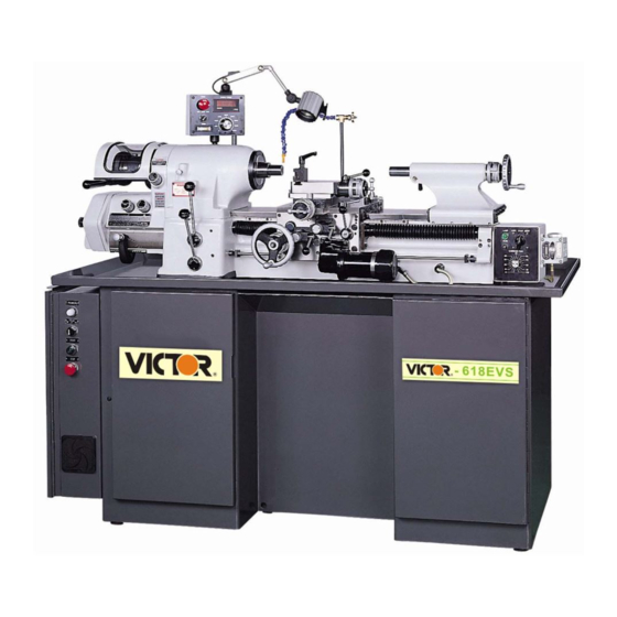
Related Manuals for Sharp 1118H


Summary of Contents for Sharp 1118H
- Page 1 OPERATION MANUAL & PARTS LIST 1118H Machine Model No.: Machine S/N.:...
-
Page 2: Table Of Contents
CONTENTS PAGE PURPOSE OF THIS MANUAL…………………………………………..LEVEL ADJUSTMENT PROCES…………….….…….……..…………... LIFTING MACHINE…………….………………………………….……..A.) INSPECTION AND CLEANING OF MACHINE………….………… B.) FOUNDATION, INSTALLATION, AND LEVELING………………… 3 C.) ELECTRICAL CONNECTIONS..…………...……………………….. D.) LUBRICATION…………….……………..…….……………………… E.) SPINDLE CONTROL LEVER…………………….…..……………… 6 F.) QUICK CHANGE GEAR BOX…….………..………………………... 7 G.) AUTOMATIC THREAD LENGTH CONTROL….…………………… 8 H.) SPINDLE BRAKE……………………………………………………... -
Page 3: Purpose Of This Manual
PURPOSE OF THIS MANUAL The model 1118H series machine is built for easy and safe operation and excellent manufacturing of work in process. The machine is built with high quality material, and carefully to exacting standards that guarantee the life, economical use, accuracy, and minimum maintenance of the machine. -
Page 4: Level Adjustment Proces
Place one spirit level in Z direction and one in X direction on slide way 1118H Level adjustment process 1. Put pads C (Figure B) under each of six points. 2. Insert the pillar A into the pedestal hole and adjust the nut B to the location according to machine level need. -
Page 5: Lifting Machine
Figure 1 – Lifting machine Lifting machine, arrange rope or cable as shown in figure 1, and check to see if the correct balance has been obtained. Then insert pads of soft cloth between the edges of the rope and machine. The net weight of this machine is approx 1050kgs (2300 lbs). So the rope or cable must be rated at 3000 lbs capacity. -
Page 6: C.) Electrical Connections
C.) ELECTRICAL CONNECTIONS The 1118H TOOLROOM LATHE is shipped completely wired and assembled, Turn Cam Switch “A” (Figure 2) to the “OFF” position, then check motor voltage. Loosen screws “B” (Figure 2), and open the switch case cover, connect the wires from the power source to the terminals (R.S.T), and ground connection is made at the “G”... -
Page 7: D.) Lubrication
D.) LUBRICATION Proper lubrication supplied carefully, will maintain the life and performance of the machine for a long period. Therefore, lubricate the machine with a high quality lubricant, and check periodically to assure that the lubricant in the oil sight gage is filled to the proper level. 1. -
Page 8: E.) Spindle Control Lever
“Z” (Figure 11) to the right to increase speed and to the left to decrease speed. The 1118H has a high and low speed range (Table 1), that moving lever "H" (Fig 11) the high or low position. To change speeds move "H" to the forward or reverse position. -
Page 9: F.) Quick Change Gear Box
F.) QUICK CHANGE GEAR BOX The Quick Change Gear Box Unit see (Figure 12 & 14), feed or thread change knob “T”, shifted to left is threading, shifted to right is feed only. The range of threads, their selection and the position of the knobs for each thread are shown on the chart “C” (Figure 13). Pull out the ball of gear change arm “A”... -
Page 10: G.) Automatic Thread Length Control
G.) AUTOMATIC THREAD LENGTH CONTROL When threading into a blind hole or to a shoulder without a thread relief. The lead screw half nut if engaged at the start of the threading work is completed. Left or right hand threads are controlled by Control lever “D”... -
Page 11: I.) Belt Adjustment
I.) BELT ADJUSTMENT Run spindle at approximately 1000 rpm. Move lever “G” (Figure 18) to center “STOP” position and let the spindle coast to a stop. This is done to equalize belt tension. Loosen lock nut “N” (Figure 19) 19mm wrench. Turn adjusting screw “P” (Figure19) 6mm socket head wrench clockwise to tighten belts. -
Page 12: L.) Collet Closer-Adjustment
L.) COLLET CLOSER ADJUSTMENT 1. Before using collet closer, and any collet or step chuck to be used should be thoroughly cleaned. 2. Push the lock Pin “E” (Figure 21). To engage lock pin, turn spindle by hand till lock pin enters notch to lock. -
Page 13: N.) Carriage Lock
Indicating Ring to required location by hand. Cross Slide operation of freed and adjustment of clutches are identical with the operation and adjustment of carriage clutches. If 1118H TOOLROOM LATHE needs to be used with the taper turning attachment, loosen the screw “S”... -
Page 14: Q.) Quick-Acting Tool Post Compound Slide Assembly
Q.) QUICK-ACTING TOOL POST COMPOUND SLIDE ASSEMBLY The compound slide has a quick-acting tool post, at the start of threading cut, place the ball-handle “H” (Figure 27) of the quick-acting tool post toward the workpiece, at the end of the threading cut, the threading tool is instantly cleared from the work by hand operated, handle “H”, for the return of the carriage to the next cut, the ball-handle lever actuating the tool post slide feed screw. -
Page 15: R.) Power Feed Unit
R.) POWER FEED UNIT The carriage Power Feed unit is mounted on the carriage. It is powered by a AC motor “M” (Figure 28). 1. The power feed can be operated only when the machine is running. Start the power feed by turning Cam Switch “S”... -
Page 16: S.) Coolant Facilities
S.) COOLANT FACILITIES The coolant pump is controlled by Switch “C” (Figure 30). Turn Switch “C” (Figure 30) to “ON” position, the pump will run continuously, turn to “AUTO” position, the pump will run only when the machine is running. If pump switch is set at “OFF” position, the coolant pump is off. -
Page 17: Thread Cutting
THREAD CUTTING CAUTION: : : : DO NOT RUN SPINDLE IN REVERSE WHEN THREADING. The SHARP 1118H is designed for rapid and accurate thread cutting. The quick-change gearbox permits instant selection of 36 different inch and metric threads. Threads can be cut to a shoulder without running into the shoulder since the automatic stop will limit carriage travel at a predetermined point in either direction. - Page 18 Set Inch/Metric knob “D” (Figure 36), so thread system to be cut reads at top of knob, If the sliding gear does not engage properly to bring desired system to read at top, loosen knob “B” (Figure 36), OPEN GEARBOX DOOR AND ROATE GEAR “T” (Figure 37), until gears mesh and knob is felt to engage detent.
- Page 19 Place lever “G” (Figure 38) in center position and engage lead screw nut “J” (Figure 40), by moving ball handled lever “H” (Figure 40) clockwise. Set two carriage stops “M” (Figure 39) approximately 1/2″ from both ends of carriage. Loosen screw “K” (Figure 39) to make area location of stops.
- Page 20 With carriage at rest and quick-acting handle “P” (Figure 42), forward in cutting position, feed the desired amount for each threading pass using cross slide handwheel “R” (Figure 42). Moe lever “G” (Figure 41), to the left and carriage will travel until it contacts stop at headstock end of machine.
-
Page 21: Outside Change Gears
OUTSIDE CHANGE GEARS The outside change gears are used to cut threads not provided in the quick-change gearbox. A set of five gears and a bracket are supplied as optional equipment. These gears, when set up to the gear chart, Figure 45 will cut 10 threads per inch or 0.25mm pitch according to set up. - Page 22 Inch Threads Using Outside Chang Gear 1. Turn disconnect switch “OFF”. 2. On inch side of change gear bracket “D” (Figure 50), mount “First Gear on Stud” “C” (Figure 50) with spacer between gears. Do not tighten bolt “A” (Figure 50) fully. 3.
- Page 23 Figure 47-Carriage and Compound Slide Figure 46-Headstock and Gearbox Figure 48-Thread Gearbox Figure 49-Threading Gearbox Figure 51-Mounting Change Gear Bracket Figure 50-Change Gear Bracket...
-
Page 24: Metric Threads Using Outside Change Gears
Metric Threads Using Outside Chang Gears 1. Turn disconnect switch “OFF”. 2. On metric side of change gear bracket “P” (Figure 56) mount “Idler Gear” “R” (Figure 56). Do not tighten bolt “S” fully. 3. Loosen knob “B” (Figure 52), open gearbox door and remove 127 tooth gear “T” (Figure 54). - Page 25 Figure 52-Headstock and Gearbox Figure 53-Carriage and Compound Slide Figure 54-Thread Gearbox Figure 55-Threading Gearbox Figure 56-Change Gear Bracket Figure 57- Mounting Change Gear Bracket Figure 58-Mounting 127 Tooth Gear...
- Page 26 HOW TO APPLY AND REMOVE SPINDLE NOSE TOOLING Fig 59 Fig60 The taper nose spindle construction is time-proven for accuracy, durability and fast, easy application and removal of spindle nose tooling. The taper holds and aligns the tooling with extreme accuracy. The precision ground slow taper holds and aligns all Tooling.
- Page 27 THERADS THREADS FIRST GEAR GEAR SCREW FIRST GEAR GEAR SCREW KNOB KNOB GEAR GEAR DLER GEAR GEAR DLER INCH INCH STUD STUD STUD STUD 22* 60* 33 22* 34 30* GEARBOX 11.5 GEARBOX GEARBOX GEARBOX GEARBOX 37 22* GEARBOX 38 30* GEARBOX 39 22* GEARBOX...
- Page 28 THERADS THREADS FIRST GEAR GEAR SCREW FIRST GEAR GEAR SCREW KNOB KNOB GEAR GEAR DLER GEAR GEAR DLER INCH INCH STUD STUD STUD STUD 29 22* 33 22* 59 22* 42 30* 34 22* GEARBOX 61 22* 43 22* 31 22* 29 22* 42 22* 44 22*...
- Page 29 THERADS THREADS FIRST GEAR GEAR SCREW FIRST GEAR GEAR SCREW KNOB KNOB GEAR GEAR DLER GEAR GEAR DLER INCH INCH STUD STUD STUD STUD 57 22* 32 22* 46 22* 41 22* 29 22* 33 22* 59 22* 34 22* 60* 22* 43 22* 61 22*...
- Page 30 PITCH PITCH SCREW TUMBLER SCREW TUMBLER KNOB 1 DLER KNOB 1 DLER GEAR GEAR GEAR GEAR .325 GEARBOX GEARBOX .375 GEARBOX GEARBOX .425 .4375 GEARBOX GEARBOX GEARBO .275 GEARBO .2875 .475 GEARBO GEARBOX...
- Page 31 PITCH PITCH SCREW TUMBLER SCREW TUMBLER KNOB 1 DLER KNOB 1 DLER GEAR GEAR GEAR GEAR GEARBOX GEARBOX .5625 .575 .875 GEARBOX GEARBOX GEARBOX GEARBOX .625 GEARBOX GEARBOX 1.02 1.06 GEARBOX 1.08 .675 GEARBOX GEARBOX 1.125 .6875 1.14 1.15 GEARBOX GEARBOX 1.16 1.18...
-
Page 32: Parts Assembly Number
PITCH PITCH SCREW TUMBLER SCREW TUMBLER KNOB 1 DLER KNOB 1 DLER GEAR GEAR GEAR GEAR 1.22 1.24 2.25 1.25 2.28 GEARBOX 1.26 2.36 GEARBOX 1.32 2.44 1.35 GEARBOX GEARBOX 1.375 2.52 GEARBOX 1.48 GEARBOX 2.75 GEARBOX 1.56 GEARBOX 1.64 1.72 1.75 GEARBOX... - Page 33 HEADSTOCK ASSEMBLY PARTS NAME PARTS NAME KEY PARTS NUMBER KEY PARTS NUMBER 1 LT-01-101 1 HEADSTOCK 39 LB-01-101 1 NUT 2 LB-01-102 1 SPINDLE NUT 40 KD02B14 1 KEY 3 2-3V0670 1 BELT 41 LT-01-106 1 HANDWHELL 4 LT-01-102F 1 SPINDLE PULLEY 42A LT-01-107A 1 DRIVER GEAR 5 KD02B042...
- Page 35 THREADING GEAR BOX ASSEMBLY PARTS NAME PARTS NAME KEY PARTS NUMBER KEY PARTS NUMBER 1 LT-11-001 1 GEAR BOX 39 LT-11-014 E.M.CONVERSION FORK 2 LT-11-002 1 GEAR BOX COVER 40 BB61805 2 BEARING 3 LT-01-206 1 GEAR 41 LT-11-015 1 GEAR 4 KD04015 1 KEY 42 RCS25...
- Page 36 THREADING GEAR BOX ASSEMBLY PARTS NAME PARTS NAME KEY PARTS NUMBER KEY PARTS NUMBER 74 LT-11-030 1 SPACE PLATE 109 LT-11-042 1 SHAFT 75 SA04006 2 SCREW 110 LT-11-043 1 CLUTCH ARM 76 PD05012 2 DOWEL PIN 111 SL04B03B 2 SCREW 77 LT-01-246 1 SLEEVE 112 SA05B100B...
- Page 37 THREADING GEAR BOX ASSEMBLY PARTS NAME PARTS NAME KEY PARTS NUMBER KEY PARTS NUMBER 142 SP02012 1 SPRING PIN 143 LT-11-050 1 COVER 144 LT-11-051 1 COVER 145 LT-01-292 1 COVER 146 SN03B08B 8 SCREW 147 LT-01-294 1 INDICATED PLATE 148 LT-11-052 1 INDICATED PLATE 149 LT-01-295...
- Page 38 THREADING GEAR BOX ASSEMBLY...
- Page 44 COLLET CLOSER ASSEMBLY PARTS NAME PARTS NAME KEY PARTS NUMBER KEY PARTS NUMBER 1 L-2001 1 LEVER YOKE 2 L-2002 2 SWIVEL BLOCK 3 L-2003 2 SCREW 4 NH12F 2 NUT 5 L-2005 2 PIVOT SCREW 6 RCS13 1 SNAP RING 7 L-2007 1 LINK PIN 8 L-2008...
- Page 46 BED ASSEMBLY PARTS NAME PARTS NAME KEY PARTS NUMBER KEY PARTS NUMBER 1 LT-03-101 1 BED BODY 33B LT-03-122B 1 BEARING SPACER 2 PD03B16B 2 PIN 34 BB72032Z 2 BEARING 3 SA05012 8 SCREW 35 LT-03-123A 1 LOCK NUT 4 LT-03-102 1 RACK 36 LT-03-124 1 LOCK NUT...
- Page 48 PADESTAL ASSEMBLY PARTS NAME PARTS NAME KEY PARTS NUMBER KEY PARTS NUMBER 1 LB-04-009 36 LT-03-103A 1 SCREW COLET HOLDER PLATE 2 LB-04-006 1 PULL ROD 37 LT-03-103B 1 SCREW 3 SN06015 3 SCREW 38 LT-03-103C 1 SCREW 4 LB-04-008 1 BUSHING 39 LT-04-004 1 COVER...
- Page 50 CARRIAGE ASSEMBLY PARTS NAME PARTS NAME KEY PARTS NUMBER KEY PARTS NUMBER 1 LT-05-104 1 ECCENTRIC ROD 2 LT-05-105 1 TAPER PLUG 3 LT-05-106 1 PLUG 4 LT-05-107A 1 HUB BLOCK 5 LT-05-108 2 NANDLE 7 LT-05-321 2 PLUG COCK 8 SN03B05B 2 SCREW 9 L-4065A...
- Page 52 GEAR BOX OF CARRIAGE ASSEMBLY PARTS NAME PARTS NAME KEY PARTS NUMBER KEY PARTS NUMBER 1 LT-05-301 1 CARRIAGE 37 SA05016 3 SCREW 2 LT-05-302 1 GEAR ASS'Y 38 LT-05-303A 1 BUSHING 4 LT-05-303 1 STUD 39 SA05010 1 SCREW 5 BAM128 4 NEDDLE BEARING 40 SL05008...
- Page 54 CROSS AND COMPOUND SLIDE ASSEMBLY PARTS NAME PARTS NAME KEY PARTS NUMBER KEY PARTS NUMBER 1 18-20206EA 1 DIAL RING 39 SN05025 4 SCREW 2 18-20211A 1 DIAL RING 40 LT-05-414 COMPOUND SLIDE GIB 3 18-20206MA 1 ZERO RING 41 LT-05-410 COMPOUND SLIDE BASE 4 18-20204 1 SUPPORT...
- Page 55 CROSS AND COMPOUND SLIDE ASSEMBLY PARTS NAME PARTS NAME KEY PARTS NUMBER KEY PARTS NUMBER 71 LT-03-111 2 NUT 72 LT-05-103 2 HANDLE 74 LT-05-419 1 GUIDE BLOCK 75 LT-05-107 1 HUB BLOCK 76 LT-05-418 1 ECCENTRIC ROD 77 SN05012 1 SCREW 78 L-4065A 1 WASHER...
- Page 57 A.C MOTOR POWER FEED CONTROL ASSEMBLY KEY PARTS NUMBER PARTS NAME KEY PARTS NUMBER PARTS NAME 3 LB-05-501F 1 INDICATOR PLATE 4 SN04008 4 SCREW 1 SELECT SWITCH SC68-36 1a 0 1a 7 SA08020 2 SCREW 10 LB-05-501 1 HOUSING 14 VR-2K 202 1 SPEED CONTROL...
- Page 59 CLUTCH ASSEMBLY PARTS NAME PARTS NAME KEY PARTS NUMBER KEY PARTS NUMBER 1 LB-05-613 2 COVER 2 NH08NF 2 NUT 3 LB-05-611 2 PRESSURE SLEEVE 4 LB-05-612 2 ADJUSTING BOLT 5 LB-05-610 2 PLUG 6 LT-05-601 2 CLUTCH CAM 7 NH08NF 2 NUT 8 LB-05-609 2 BEARING SPACER...
- Page 61 A.C MOTOR ASSEMBLY PARTS NAME PARTS NAME KEY PARTS NUMBER KEY PARTS NUMBER 1 LB-05-721-A CONNECTING ADAPTER 2 SH05015 2 SCREW 3 SA06020 4 SCREW 6 RCR35 1 RETAINING RING 7 KD03015 2 KEY 8 BB6003ZZ 1 BEARING 9 LT-05-708-1 1 WORM SHAFT 10 BB6000ZZ 1 BEARING...
- Page 63 VARIABLE SPEED CONTROL BOX ASSEMBLY PARTS NAME PARTS NAME KEY PARTS NUMBER KEY PARTS NUMBER 1 LB-06-303F 1 CONTROL BOX 2 LT-06-301F SPEED INDICATOR PLATE 3 22mm 2a 3 B 1 TOGGLE SWITCH 4 SN05008 4 SCREW 5 L-6405F 1 SUPPORT POST 6 SL06010 2 SCREW 7 PCB-04B 1/2"...
- Page 65 TAILSTOCK ASSEMBLY PARTS NAME PARTS NAME KEY PARTS NUMBER KEY PARTS NUMBER 1 LT-09-101 1 TAILSTOCK BODY 37 LT-09-115 1 HANDLE 2 PD05040 1 PIN 38 LT-09-117 1 BUSHING 3 NH10 1 NUT 39 LT-09-109 1 LOCK BOLT 4 WB10 1 WASHER 40 LT-09-109A 1 LOCK BLOCK...
- Page 68 Sharp Industries, Inc 3501 Challenger Street Torrance, CA 90503 Tel: (310) 370-5990 Fax: (310) 542-6162 Parts and Service: (310) 323-3181 Email: [email protected] Parts: [email protected] Support:mail to [email protected]...