
Related Manuals for GE eBike


Summary of Contents for GE eBike
- Page 1 / eBike L / eBike EL Service Manual 2018112-003 Revision J 2018112-003 Rev J eBike, eBike L, eBike EL - I -...
- Page 2 ESD. • • • • • GE Medical Systems Information Technologies GmbH considers itself responsible for the effects on safety, reliability, and performance of the equipment, only if: assembly operations, extensions, readjustments, modifications, or repairs are carried out...
- Page 3 Revision History Revision History This manual is subject to the GE Medical Systems Information Technologies change order service. The revision code, a letter that follows the document part number, changes with every update of the manual. The initial version of the manual has the letter A.
-
Page 4: Table Of Contents
B-3.1.2 eBike L: Remove Casing ......................22 B-3.1.3 eBike L: Replace Saddle Motor ....................24 B-3.1.4 eBike L: Install Power Supply Module for eBike L (P/N 2018111-142) ..........25 B-3.1.5 eBike L: Replace Lift Motor for Couch Adjustment ................ 26 B-3.1.6 eBike L: Replace Motor Control Unit ..................... - Page 5 C-3 Overview: PCBs eBike .................... 46 C-4 Overview: DIP Switch and Jumper Settings ............. 48 Part D: Service Menu for eBike Basic / Comfort / L / EL ........... 49 Part E: Drive Unit ......................65 E-1. Drive Unit - Mechanical Design ................65 E-2.
- Page 6 For your notes - VI - eBike, eBike L, ebike EL 2018112-003 Rev J...
-
Page 7: Safety Information
Note Suitable common ground terminal: Bicycle ergometer eBike Basic / Comfort: screw of the levelling device Ergometer eBike L/EL: screw head of the protective earth connection between swivelling section and ergometer base A device is considered to be unsafe, when it cannot be repaired the user does not wish to have the device repaired. -
Page 8: Inspection According To German Medical Device Operator Ordinance
According to §6 and §11 of the German Medical Device Operator Ordinance, the load unit must be inspected to the approved rules of the art at intervals of 2 years by a GE Medical Systems Information Technologies authorized Service technician, and repaired if necessary. -
Page 9: Final Checkout Procedure / Functional Test
A-2. Final Checkout Procedure / Functional Test These tests must be performed as the final checkout and test procedure after every safety inspection, maintenance and repair of the product. A-2.1. Final Checkout Procedure and Functional Test of eBike Basic, eBike Comfort 1. Visually inspect the device Inspect coat of lacquer, cables/power cord, bellows on steering column and saddle. -
Page 10: A-2.2 Final Checkout Procedure And Functional Test Of Ebike L
Check remote start if applicable. Expected result: Ergometer can be controlled by external unit Pass/Fail A-2.2 Final Checkout Procedure and Functional Test of eBike L 1. Visually inspect the device Inspect coat of lacquer, cables/power cord, bellows on steering column and saddle. -
Page 11: A-2.3 Final Checkout Procedure And Functional Test Of Ebike El
Check remote start if applicable. Expected result: Ergometer can be controlled by external unit Pass/Fail A-2.3 Final Checkout Procedure and Functional Test of eBike EL 1. Visually inspect the device Inspect coat of lacquer, cables/power cord, bellows on steering column and saddle. - Page 12 If ergometer is remote-controlled from EKG unit or PC-ECG system, check connection cable. Check load control vial EKG unit or PC ECG system. Check remote start if applicable. Expected result: Ergometer can be controlled by external unit Pass/Fail - 6 - eBike, eBike L, eBike EL 2018112-003 Rev J...
- Page 13 Bemerkungen: 20_ _ Jahr der nächsten notwendigen messtechnischen Kontrolle: Datum: ______________________ Unterschrift : __________________________ GE Medical Systems Information Technologies GmbH, Munzinger Str. 3, D-79111 Freiburg, Germany 2018112-003 Rev J eBike, eBike L, eBike EL - 7 -...
- Page 14 Bemerkungen: 20_ _ Jahr der nächsten turnusmäßigen messtechnischen Kontrolle: Datum: ______________________ Unterschrift : __________________________ GE Medical Systems Information Technologies GmbH, Munzinger Str. 3, D-79111 Freiburg, Germany - 8 - eBike, eBike L, eBike EL 2018112-003 Rev J...
-
Page 15: Part B. Mechanical Design
PC with control terminal PCplus 1, 2 Figure B-1: Operating controls of bicycle ergometers eBike basic / comfort Power input with mains fuse (section 2.3.1) Clamping lever for angle adjustment Interfaces (on bottom of ergometer) -
Page 16: B.1.B Operating Controls And Connections Of Ebike L
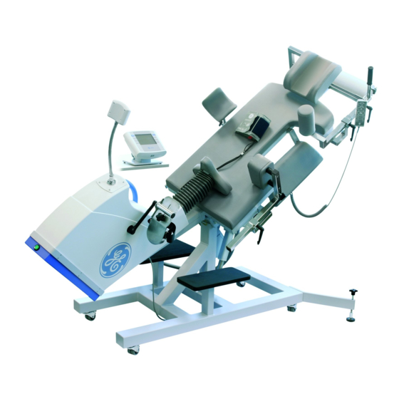
B: Mechanical Design B.1.b Operating Controls and Connections of eBike L Figure B-2: Operating controls of bicycle ergometers eBike L Clamping lever for adjustment of the head Leg rest (option) support Castors, locking Arm rest for blood pressure measurements Paper roll... -
Page 17: B.1.C Operating Controls And Connections Of Ebike El
B: Mechanical Design B.1.c Operating Controls and Connections of eBike EL Figure B-3: Operating controls of bicycle ergometers eBike EL Clamping lever for adjustment of the head Upper handgrip, adjustable support, release button for drop section 14 Remote control for adjustment of bed surface... -
Page 18: B.1.D Connections And Data Ports Of The Ebike
L / EL connection panel eBike L / EL cuff connection Figure B-3: Connections and data ports of systems eBike L and eBike EL PORT 1: Digital RS232 interface (9-pin Sub-D) for data communication with PC and EKG unit and output for remote start of the EKG unit. -
Page 19: Overview: Mechanical Design Ebike
B4-4a B4-4b B4-2 B4-1 B4-6a B4-5a B4-6b B4-5b B4-7 B4-8 Figure B-4: Mechanical design of bicycle ergometers eBike basic Item No. Part No. Description B4-1 Ergometer base B4-2 Load unit, fully assembled for eBike B4-3 Power supply with power switch... -
Page 20: B-2.1 Overview: Disassembling The Ebike Basic/Comfort
3 mm, minimum length 15 mm NOTE: Use the same tools to disassemble eBike L and eBike EL. Two wide metal angles may be required to remove the ergometer casing (side length approx. 1.5 cm x 15 cm). - Page 21 Using the round pins (max. diameter of 3 mm), simultaneously press in the the plastic tabs on the left and right and lift off the cover 2018112-003 Rev J eBike, eBike L, eBike EL - 15 -...
- Page 22 7. Remove front and rear connection piece. • Loosen each hexagon socket screw on one side. • Remove front and rear connection piece. - 16 - eBike, eBike L, eBike EL 2018112-003 Rev J...
- Page 23 • Carefully separate the two shells. 9. Reverse the above steps to reassemble. e. Install Power Supply Module for eBike basic & comfort (P/N 2018111-141) Replacement of large power supply ERS80US24M or small power supply EMC60US24.
- Page 24 B: Mechanical Design f. Remove Saddle Motor (eBike comfort only) Note: Position the saddle at mid-level before removing the saddle motor. Once the power supply has been removed, you can proceed to removing the saddle motor. • Disconnect connection cable of the saddle motor from PCB Interface Sitz-Motor X152 and the connection cable of the saddle height sensor Sitz-Sens X155.
- Page 25 • Loosen clamping lever (eBike comfort) securing the handlebar or loosen fixation of the steering column (eBike basic). Caution: ultra-tight screw lock. In each case take care not to drop the clamping plate. • Lift off the steering column.
- Page 26 • Remove cable ties. • Remove cable connecting PCB BP to PDB Display. • Disconnect air tubing. When reassembling the control terminal, ensure proper positioning of cables and tubing. - 20 - eBike, eBike L, eBike EL 2018112-003 Rev J...
-
Page 27: B-3. Overview: Mechanical Design Ebike L
B5-8 Saddle motor for eBike L B5-9 Motor control with hand switch, 2 channels for eBike L (1 - lift motor, 2 - saddle motor, 3 - remote control, 4 - mains connection) B5-10 Control terminal for eBike L (eBike L basic only) -
Page 28: B-3.1 Overview: Disassembling Ebike L
B: Mechanical Design B-3.1 Overview: Disassembling eBike L B-3.1.1 eBike L: Remove Connection Box The connection box houses the interface board and the ON/OFF switch. In addition, the blood pressure pump module (option) is directly mounted on the frame (see Figure B5-5). - Page 29 Ground clamp at the bottom of the swivel section (see red arrow a in illustration at left) Ground cable (see b and c in illustration at right) (secured with adjustable cable tie) eBike L basic with blood pressure only: blood pressure tubing d + microphone cable eBike L external only: disconnect cable for speed indication (RMP) c.
-
Page 30: B-3.1.3 Ebike L: Replace Saddle Motor
B: Mechanical Design B-3.1.3 eBike L: Replace Saddle Motor Troubleshooting: Before replacing the saddle motor make sure that the motor is actually defective. For this check, switch the hexagon socket of the saddle motor from channel 2 to channel 1. -
Page 31: B-3.1.4 Ebike L: Install Power Supply Module For Ebike L (P/N 2018111-142)
B: Mechanical Design B-3.1.4 eBike L: Install Power Supply Module for eBike L (P/N 2018111-142) Replacement of large power supply ERS80US24M or small power supply EMC60US24. When replacing the power supply, it is mandatory to replace the supplied connection cable as well. -
Page 32: B-3.1.5 Ebike L: Replace Lift Motor For Couch Adjustment
Ensure that the connection is in the middle of the length of tubing. 4. Now connect the cable to the power supply. B-3.1.5 eBike L: Replace Lift Motor for Couch Adjustment Troubleshooting: Before replacing the lift motor for couch adjustment make sure that the motor is actually defective. -
Page 33: B-3.1.6 Ebike L: Replace Motor Control Unit
Troubleshooting: Before replacing the motor control unit make sure that it is actually defective. For this check, use a new hand switch (the hand switch for eBike EL can also be used) and test the motor functions. If the control unit does not work, it is out of order and must be replaced. If it works, the hand switch is defective. -
Page 34: B-4.Overview: Mechanical Design Ebike El
Saddle motor for eBike EL B10-9 Motor control with hand switch, 3 channels for eBike EL (1 - lift motor, longitudinal, 2 - lift motor, left lateral tilt, 3 - saddle motor, 4 - remote control, 5 - mains connection) -
Page 35: B-4.1 Overview: Disassembling Ebike El
B: Mechanical Design B-4.1 Overview: Disassembling eBike EL B-4.1.1 eBike EL: Remove Connection Box The connection box houses the interface board and the ON/OFF switch. In addition, the blood pressure pump module (option) is directly mounted on the frame (see Figure B5-5). - Page 36 Ground clamp at the bottom of the swivel section (see red arrow 1 in illustration at left) Ground cable (see red arrows in illustration at right) (secured with adjustable cable tie) eBike EL basic with blood pressure only: blood pressure tubing + microphone cable eBike EL external only: disconnect cable for speed indication (RMP) c.
-
Page 37: B-4.1.3 Ebike El: Replace Saddle Motor
B: Mechanical Design B-4.1.3 eBike EL: Replace Saddle Motor Troubleshooting: Before replacing the saddle motor make sure that it is actually defective. For this check, switch the hexagon socket of the saddle motor from channel 3 to channel 1 or 2. -
Page 38: B-4.1.4 Ebike El: Install Power Supply Module For Ebike El (P/N 2018111-142)
B: Mechanical Design B-4.1.4 eBike EL: Install Power Supply Module for eBike EL (P/N 2018111-142) Replacement of large power supply ERS80US24M or small power supply EMC60US24. When replacing the power supply, it is mandatory to replace the supplied connection cable as well. -
Page 39: B-4.1.5Ebike El: Replace Lift Motors For Couch Adjustment
To do so, first turn jack plug counterclockwise as far as possible (e.g. using a suitable fork wrench), then pull out the jack plug. 2018112-003 Rev J eBike, eBike L, eBike EL - 33 -... -
Page 40: B-4.1.6 Ebike El: Replace Motor Control Unit
Before replacing the motor control unit make sure that it is actually defective. For this check, use a new hand switch for eBike EL and test the motor functions. If the control unit does not work, it is out of order and must be replaced. -
Page 41: B-4.1.7 Ebike El Basic: Replace Control Panel
- microphone cable (option) d - air hose (option) B-4.1.8 eBike EL External: Replace External Speed Indicator Note: Before you can remove the external speed indicator, you will have to lift the casing a little (see section B-4.1.2, item 5b) for details. - Page 42 B: Mechanical Design For your notes - 36 - eBike, eBike L, eBike EL 2018112-003 Rev J...
-
Page 43: Part C. Electrical Design
μ μ μ μ μ C strain gauge drive unit blue ON/OFF switch PCB RPM sensor (= PCBRPM) Figure C-1: Block Diagram eBike Basic / eBike Comfort for RPM Board 1 2018112-003 Rev J eBike, eBike L, eBike EL - 37 -... -
Page 44: C-1.2 Block Diagram Ebike Basic / Ebike Comfort For Rpm Board 2
C: Electrical Design C-1.2 Block Diagram eBike Basic / eBike Comfort for RPM Board 2 Figure C-2: Block Diagram eBike Basic / eBike Comfort for RPM Board 2 - 38 - eBike, eBike L, eBike EL 2018112-003 Rev J... -
Page 45: C-1.3 Block Diagram Ebike L For Rpm Board 1
L 230 V AC SUB-D connector power connector 120 V AC remote control Figure C-3: Block Diagram eBike L for RPM Board 1 2018112-003 Rev J eBike, eBike L, eBike EL - 39 -... -
Page 46: C-1.4 Block Diagram Ebike L For Rpm Board 2
C: Electrical Design C-1.4 Block Diagram eBike L for RPM Board 2 Figure C-4: Block Diagram eBike L for RPM Board 2 - 40 - eBike, eBike L, eBike EL 2018112-003 Rev J... -
Page 47: C-1.5 Block Diagram Ebike El For Rpm Board 1
EL 230 V AC motor, lateral tilt power connector SUB-D connector 120 V AC remote control Figure C-5: Block Diagram eBike EL for RPM Board 1 2018112-003 Rev J eBike, eBike L, eBike EL - 41 -... -
Page 48: C-1.6 Block Diagram Ebike El For Rpm Board 2
C: Electrical Design C-1.6 Block Diagram eBike EL for RPM Board 2 Figure C-6: Block Diagram eBike EL for RPM Board 2 - 42 - eBike, eBike L, eBike EL 2018112-003 Rev J... -
Page 49: C-2.1 Wiring Diagram Ebike Basic / Ebike Comfort
C: Electrical Design C-2.1 Wiring Diagram eBike Basic / eBike Comfort Figure C-7: eBike Basic / eBike Comfort Wiring Diagram 2018112-003 Rev J eBike, eBike L, eBike EL - 43 -... -
Page 50: C-2.2 Wiring Diagram Ebike L
C: Electrical Design C-2.2 Wiring Diagram eBike L Figure C-8: eBike L Wiring Diagram - 44 - eBike, eBike L, eBike EL 2018112-003 Rev J... -
Page 51: C-2.3 Wiring Diagram Ebike El
C: Electrical Design C-2.3 Wiring Diagram eBike EL Figure C-9: eBike EL Wiring 2018112-003 Rev J eBike, eBike L, eBike EL - 45 -... -
Page 52: Overview: Pcbs Ebike
C: Electrical Design Overview: PCBs eBike Figure C-10: PCB Interface (= PCBIF) eBike Basic / Comfort (shown at left) and for eBike L / EL installed in connection box (shown at right) Figure C-11a: PCB RPM (= PCBRPM) eBike with strain gauge... - Page 53 C: Electrical Design obsolete obsolete Figure C-12a: Power supplies eBike Basic / Comfort replacement Figure C-12b: Power supply eBike Basic / Comfort obsolete obsolete Figure C-12c: Power supplies eBike L/EL replacement Figure C-12d: Power supply eBike L/EL 2018112-003 Rev J...
-
Page 54: Overview: Dip Switch And Jumper Settings
C: Electrical Design C-4. Overview: DIP Switch and Jumper Settings red: current DIP switch position Figure C-13: Overview: DIP Switch and Jumper Settings - 48 - eBike, eBike L, eBike EL 2018112-003 Rev J... -
Page 55: Part D: Service Menu For Ebike Basic / Comfort / L / El
D: Service Menu Part D: Service Menu for eBike Basic / Comfort / L / EL Note: The service menus are the same for both the Control Terminal PC and the Control Termi- nal PCplus. The menus shown below are from Control Terminal PC. - Page 56 1200, 2400, 4800, 9600, 19200, 38400, 57600, 115200 baud Note: Always select a baud rate of 4800 baud. Load calibration eBike, eBike L, eBike EL of PCBRPM Board Note: When using With software version FW1.6 the calibration procedure was redesigned. PCBRPM Board...
- Page 57 If you turn the ergometer on again and the weight is still attached, the error code E:02 will appear. The unit is locked and will not enter the normal operating mode. 2018112-003 Rev J eBike, eBike L, eBike EL - 51 -...
- Page 58 D: Service Menu 2b. Load calibration eBike, eBike L, eBike EL of PCBRPM Board 2: With software version FW1.6 the calibration procedure was redesigned. Take the seat ergometer to an elevated position, e.g. between two solid chairs. Support the supine ergometer so that the load unit will be in a horizontal position.
- Page 59 If you turn the ergometer on again and the weight is still attached, the error code E:02 will appear. The unit is locked and will not enter the normal operating mode. 2018112-003 Rev J eBike, eBike L, eBike EL - 53 -...
- Page 60 1. Place the ergometer on a level surface and put it into operation. 2. Set the back rest of eBike L to an angle of 45° (semi- recumbent position), using the remote control. Adjust eBike EL to a lateral tilt of 0°, using the remote control.
- Page 61 Note: The calibration of the analog load output signal can only be verified, after the Service Menu has been terminated. The analog output signal can be checked after starting an ergometry test. 2018112-003 Rev J eBike, eBike L, eBike EL - 55 -...
- Page 62 If the eBike has the serial no range beginning with: 2004000268 up to 2004001139 The Flash Eprom in the eBike Terminal has to be replaced. The Software Version 1.2 or higher is only running with the new Flash Eprom. eBike’s with serial no higher 2004001139 has already this new Flash Eprom implemended.
- Page 63 Figure D-1: Pin assignment for software update all eBikes Firmware FW1.8 is used. Copy the update program 2020259-009 SW FIRMWARE EBIKE FW18.zip to a directory on the PC (e.g. C:\Update_eBike), unpack the file and save the corresponding update files to the same directory. Note: The Software file cannot be ordered.
- Page 64 - wait approx. 15 sec" is displayed. Don't switch off the ergometer. Once the update has been completed, the message “Download success !!! Close Application !” will appear. Confirm the message with “Yes”. - 58 - eBike, eBike L, eBike EL 2018112-003 Rev J...
- Page 65 Note: After the update is complete the message "Software Update - FW 1.8 - Update finished - Switch off power" is displayed. eBike: After a successful update, turn the ergometer off and on again and check the software version in the menu - Software Version FW 1.8.
- Page 66 The start of the RPM board download required a long time (min. 25 s). Set the miniature switch to the “PROG OFF” position (see picture above) after finishing the download. - 60 - eBike, eBike L, eBike EL 2018112-003 Rev J...
- Page 67 Incorrect transfer of data Do not turn off ergometer and The update software reports an packets. repeat update. error during Nibp or Med1 update. Software modules not Perform software update E90...E93 compatible. 2018112-003 Rev J eBike, eBike L, eBike EL - 61 -...
- Page 68 Note: Error Code E:01 will be displayed after switching on the eBike, when the cuff was moved during self-test. In this case the amplifier cannot be initialized and the eBike has to be started again. E:01 will not be recorded and will not appear here.
- Page 69 Note: If the ergometer is controlled by an external EKG unit (serial or analog/serial control), always select the setting Automatic “Yes”. 9. Saddle Calibration (eBike Basic/Comfort only) The saddle calibration determines the display range (scale from 1 to 40) of the digital saddle height indication.
- Page 70 Note: According to the German Medical Device Act (MPG), only GEMS IT authorized personnel is allowed to calibrate the NIBP system. Note: eBike L / eBike EL have the cuff connection on the right or left of the couch. 11. NIBP Test Use a pump to apply pressure from outside.
-
Page 71: Part E: Drive Unit
Pins fastening the two micro ropes to the eddy-current brake 1-18 4-pin connector to PCB RPM 1-19 Hook for calibration weight — Load unit type eBike, complete kit with strain gauge and PCB RPM 2018112-003 Rev J eBike, eBike L, eBike EL - 65 -... - Page 72 The chain is linked with a chain lock. Once the lock has been opened, the chain can be removed. Replacement: For servicing, the entire drive unit can be replaced. Drive unit with straing gauge and PCB RPM, assembled. - 66 - eBike, eBike L, eBike EL 2018112-003 Rev J...
-
Page 73: E-2. Troubleshooting And Repairs
Disconnect the following cables before replacing PCB RPM: cable to strain gauge cable to power supply and RS232 interface cable to eddy-current brake Caution: After replacing PCB RPM, repeat weight calibration (torque calibration) of ergometer. 2018112-003 Rev J eBike, eBike L, eBike EL - 67 -... -
Page 74: E-2.3 Rpm Board : Replacement And Adjustment Procedure
Dismantle Ergometer as described in Service Manual. Cut cable tie. Disconnect cable to strain gauge (black wire at the bottom). Remove fixation screws of RPM board Disconnect both cables to eddy-current brake. - 68 - eBike, eBike L, eBike EL 2018112-003 Rev J... - Page 75 Discconect ergometer from mains. Fix RPM board again. Perform load calibration as described with 8 kg weight 2018112-003 Rev J eBike, eBike L, eBike EL - 69 -...
- Page 76 Fix PCBRPM board 2 with the screws. Connect ergometer to mains, switch on the ergometer and enter the service menu. Follow the procedure described in section 2b. - 70 - eBike, eBike L, eBike EL 2018112-003 Rev J...
-
Page 77: Part F: Servicing Instructions
F: Servicing Instructions Part F: Servicing Instructions F-1. Spare Parts for Repair of eBike Overview: Adjustments required after replacement of assemblies Replaced Assembly Required Adjustment chassis no replacement drive unit with PCB RPM no adjustment required PCB RPM requires calibration (8 kg) -
Page 78: F-2. Spare Parts For Repair Of Ebike L / Ebike El
F: Servicing Instructions F-2. Spare Parts for Repair of eBike L / eBike EL Overview: Adjustments required after replacement of assemblies Replaced Required Required Assembly Adjustment Procedures chassis no replacement drive unit with PCB RPM no adjustment required removing casing... -
Page 79: F-3. Add-On "Bp Module Ebike
F-3. Add-on “BP Module eBike“ 2017911-089 ERGOMETER EBIKE BP ADD-ON KIT for use with 2017911-001 eBike basic with control terminal PC 2017911-002 eBike basic with control terminal PCplus 2017911-005 eBike comfort with control terminal PC 2017911-006 eBike comfort with control terminal PCplus... -
Page 80: F-4. Add-On "Bp Module Ebike L" & "Bp Module Ebike El
F: Servicing Instructions F-4. Add-on “BP Module eBike L“ & “BP Module eBike EL“ Two different BP add-on kits are available for the couch ergometers eBike L & eBike EL: 2017911-036 ERGOMETER EBIKE L&EL BP ADD-ON KIT for use with... -
Page 81: Appendix A: Interfaces
Appendix A: Interfaces Appendix A: Interfaces The modular ergometer system eBike has several interfaces. Digital as well as analog data can be exchanged with the ergometer. These interfaces thus allow the ergometer to be fully controlled from a PC or EKG unit and they also permit a mere transfer of data from the ergometer to the EKG unit and... -
Page 82: Setup For: Digital Ecg Unit
IerxxxP10Vyyy identifies the ergometer The string contains the ergometer model „xxx“ and the software version. Note: For compatibility with er900, the transferred string reads „er900P10VV243“. - 76 - eBike, eBike L, eBike EL 2018112-003 Rev J... -
Page 83: Digital Interface Port 2: For Service Purposes Only
Pin 9 • Voltages: logic low logic high Transmit Output (Pin 2) > +7 V > -7 V Receive Input (Pin 3) > +3 V > - 3 V 2018112-003 Rev J eBike, eBike L, eBike EL - 77 -... -
Page 84: Analog Interfaces With Digital Data Transfer
The command Sinitiates a BP measurement. Upon termination of the BP measurement, the ergometer outputs the data record. No.xx, SYST:xxx mmHg, DIAST: xxx mmHg, Pulse: xxx/min where No.xxis used to identify the consecutive BP measurements (No.01, No.02, ...). - 78 - eBike, eBike L, eBike EL 2018112-003 Rev J... -
Page 85: Appendix B: Spare Parts / Service Kits For Ebike
Appendix B: Spare Parts Appendix B: Spare Parts / Service Kits for eBike Part No. Short Description Description 2017911-010 SPLY EBIKE CUFF ADULT STD TUBE 130CM BP cuff, adults, 130 cm tubing 2017911-011 SPLY EBIKE CUFF ADULT STD TUBE 200CM... - Page 86 2018111-002 SPARE EBIKE HANDLEBAR TUBE W CABLE Service Kit: handlebar tube with spiral cable, comprising: - handlebar tube, galvanized, yellow, for eBike basic/comfort - spiral cable CAN, incl. connection for control terminal - dual spiral cable, black and blue (ECG + NIBP) - 3x tubing joints GS4 - incl.
- Page 87 2018111-008 SPARE EBIKE CABLE FOR SADDLE HEIGHT DSPLY Cable connecting interface to saddle height display 2018111-009 SPARE EBIKE/B SADDLE TUBE Service Kit: Assembled saddle tube w/o. motor for eBike basic, consisting of: 1x saddle guide tube w/o. motor 55x55x2 for eBike basic 1x saddle tube w/o.
- Page 88 2018111-017 SPARE EBIKE/B COVER SET R/L Service Kit: casing eBike basic (GE), kit consisting of: 1x side panel eBike basic, left, with silk-screened GE logo 1x side panel eBike basic, right, with silk-screened GE logo 2x connection piece, diam. 10, length 100 mm 10x washer U4.3x9x0.8...
- Page 89 2018111-018 SPARE EBIKE/C COVER SET R/L Service Kit: casing eBike comfort (GE), kit consisting of: 1x side panel eBike comfort, left, with silk-screened GE logo 1x side panel eBike comfort, right, with silk-screened GE logo 2x connection piece, diam. 10, length 100 mm 10x washer U4.3x9x0.8...
- Page 90 Part No. Short Description Description Handlebar eBike 2018111-025 SPARE EBIKE ADAPTER TERMINAL Service Kit: Control terminal adapter for eBike consisting of: 1x control terminal adapter, 2 parts 2x star washer Z 8.4x15x0.8 2x screw M8x35 1x clamping lever M8x30 for clamping of handlebar 2x screw M6x25 cyl., slot...
- Page 91 1x clamping plate 2x star washer F3.2 2x screw M3x10 1x micro rope, short, diam. 0.81 mm 7x7, length 88.7 mm, for eBike 2018111-033 SPARE EBIKE RETURN SPRING Service Kit: return spring with micro rope, consisting of: 1x return spring with micro rope, diam. 0.6 mm 1x19, length 125 mm 1x clamping plate 2x star washer F3.2...
- Page 92 2018111-039 SPARE EBIKE CABLE MAINS EURO Power cord, grey, length 2.5 m, German connector PCBs eBike: 2018111-040 SPARE EBIKE/C PCB INTERFACE PCB Interface kit for eBike comfort with saddle motor: 1x interface module, pre-assembled 4x screw M4x8 2018111-137 SPARE EBIKE/B PCB INTERFACE...
- Page 93 4x screw M4x8 Control Terminal eBike PC 2018111-043 SPARE EBIKE TERMINAL PC NEW control terminal, new, control terminal PC, standard (= w/o. BP), GE 2x screw M4x10, combi-slotted 2018111-044 SPARE EBIKE TERMINAL PC W BP NEW control terminal, new, control terminal PC, with BP module, GE...
- Page 94 4x screw M3x12 2018111-053 SPARE EBIKE TERMINAL P/K HOUSING BOTTOM Service Kit: control terminal housing, bottom shell consisting of: 1x control terminal housing, bottom shell for control terminal eBike 1x display window control terminal top (RPM window) 4x screw M3x12 2018111-054 SPARE EBIKE TERMINAL PANEL W/O BP connector panel, bottom, for control terminal w/o.
- Page 95 10x cable tie 2.4, length 95 mm Documentation 2018112-001 MNL OPR EBIKE PC Operator’s Manual System eBike, PC 2018112-002 MNL OPR EBIKE PCPLUS Operator’s Manual System eBike, PCPlus terminal 2018112-003 MNL SVCE EBIKE Servicing Instructions System eBike, English Service tools 2018111-135 8 kg cailbration weight, incl.
-
Page 96: Appendix B.2: Spare Parts / Service Kits For Ebike L / Ebike El
1x BP cuff shackle, standard, 130 cm tubing 1x Addendum for BP Module retrofit kit 2017911-043 ERGOMETER EBIKE L&EL EXT TRMNL BP ADD-ON KIT Service Kit: Retrofit Kit Blood Pressure Module External for eBike L / EL comprising: 1x PCB BP for control terminal incl. - Page 97 Appendix B.2: Spare Parts eBike L / eBike EL Part No. Short Description Description 2017911-010 SPLY EBIKE CUFF ADULT STD TUBE 130CM BP cuff, adults, 130 cm tubing 2017911-011 SPLY EBIKE CUFF ADULT STD TUBE 200CM BP cuff, adults, 200 cm tubing...
- Page 98 1x retaining piece bellows saddle 4x washer U 4.3 4x screw 3.5 x 16 2018111-067 SPARE EBIKE L&EL SADDLE MOTOR Service Kit: Saddle motor eBike L / EL, complete, comprising: 1x saddle motor eBike L / EL 1x stud screw SW19 2x washer U13...
- Page 99 1x clamping plate 2x star washer F3.2 2x screw M3x10 1x micro rope, short, diam. 0.81 mm 7x7, length 88.7 mm, for eBike 2018111-033 SPARE EBIKE RETURN SPRING Service Kit: return spring with CGA micro rope, comprising 1x return spring with CGA micro rope, diam. 0.6 mm 1x19, length 125 mm 1x clamping plate 2x star washer F3.2...
- Page 100 Service Kit: Earth cable, kit for eBike L/EL comprising: 1x earth cable from base to swivel section (eBike L and EL) 1x earth cable from base joint head to swivel section (eBike EL only) 8x washer Z4.3 4x washer U4.3...
- Page 101 Appendix B.2: Spare Parts eBike L / eBike EL Part No. Short Description Description 2018111-079 SPARE EBIKE L&EL TERMINAL PP W BP NEW Service Kit: Control erminal, new, PCplus terminal L/EL, with blood pressure, comprising: 1 x control terminal, new, PCplus terminal L/EL, with blood pressure...
- Page 102 1x guide rail 4x stand-off, diam. 14, length 12 4x screw M6x30 2018111-092 SPARE EBIKE L MOTOR CONTROLLER 240V Service Kit: Motor controller magnetic 230 V for eBike L, dual-channel, comprising: 1x motor controller magnetic 230V/50Hz, dual-channel 4x washer 4.3...
- Page 103 Appendix B.2: Spare Parts eBike L / eBike EL Part No. Short Description Description 2018111-094 SPARE EBIKE EL MOTOR CONTROLLER 240V Service Kit: Motor controller magnetic 230 V for eBike EL, three- channel, comprising: 1x motor controller magnetic 230V/50Hz, three-channel 4x washer 4.3 4x screw M4x16 2018111-095 SPARE EBIKE L&EL MOTOR CONTROLLER 120V...
- Page 104 Service Kit: Foot board, small, for eBike L/EL comprising: 1x foot board small 370x180x20 4x screw 5x17 (with eBike L: 1 each is used on the right and left) (with eBike EL: 1 is used on the left) 4x washer U6.4...
- Page 105 Upholstery eBike L / eBike EL 2018111-116 SPARE EBIKE EL LEG REST RIGHT Service Kit: Leg rest, right, for eBike L / EL, comprising: 1x leg rest, right, complete with upholstery, grey, mounted 2018111-117 SPARE EBIKE EL LEG REST LEFT...
- Page 106 Short Description Description 2018111-123 SPARE EBIKE EL GUIDE TUBE ARMPIT SUPPORT Service Kit: Guide tube armpit support (eBike EL only) comprising: 1x guide tube armpit support (see arrow in sketch, right) 2x Novogrip clamping lever M10x15 2x reinforcing angles 34x25x2...
- Page 107 Part No. Short Description Description 2018111-131 SPARE EBIKE EL DROP SECTION COMPLETE Service Kit: Drop section, complete with holder (eBike EL only), comprising: 1x drop section, complete with holder (eBike EL only) 1x retaining screw M8x20 2018111-132 SPARE EBIKE EL DROP CUSHION SINGLE...
- Page 108 Appendix B.2: Spare Parts eBike L / eBike EL For your notes - 102 - eBike, eBike L, eBike EL 2018112-003 Rev J...
-
Page 109: Appendix C.1: Technical Specifications Ebike Basic / Ebike Comfort
Appendix C: Technical Specifications Appendix C.1: Technical Specifications eBike Basic / eBike Comfort Ergometer Model: modular ergometer system eBike, models eBike basic, eBike comfort operating mode: continuous operation power: 100 - 240 V / 50 - 60 Hz power consumption: 60 VA max. - Page 110 3 mmHg/beat or approx. 3 mmHg/s calibration: calibration with external pressure meter artefact rejection: automatic artifact rejection and comparison of the resting BP readings of both methods for plausibility - 104 - eBike, eBike L, eBike EL 2018112-003 Rev J...
-
Page 111: Appendix C.2: Technical Specifications Ebike L
Appendix C: Technical Specifications Appendix C.2: Technical Specifications eBike L Ergometer Model Environment – modular ergometer system eBike L Operation Operating Mode – temperature between +10 and +40 °C (50 and 104 °F) – continuous operation – relative humidity 30 to 75 %, no condensation Power Supply –... -
Page 112: Appendix C.3: Technical Specifications Ebike El
Appendix C: Technical Specifications Appendix C.3: Technical Specifications eBike EL Environment Ergometer Model Operation – modular ergometer system eBike EL – temperature between +10 and +40 °C (50 and 104 °F) Operating Mode – relative humidity 30 to 75 %, no condensation –... - Page 113 Appendix C: Technical Specifications Family of characteristics of the braking torque control range „eBike system“ speed-independent range to DIN VDE 0750-0238 speed-independent range, eBike system 2018112-003 Rev J eBike, eBike L, eBike EL - 107 -...
- Page 114 Asia Headquarters World Headquarters GE Medical Systems GE Medical Systems GE Medical Systems Information Technologies GmbH Information Technologies Asia; GE (China) Co., Ltd. Information Technologies, Inc. Munzinger Straße 3-5 24th Floor, Shanghai MAXDO Center, 8200 West Tower Avenue D-79111 Freiburg...