
Related Manuals for Mitsubishi Electric LT2-2250-B1T


Summary of Contents for Mitsubishi Electric LT2-2250-B1T
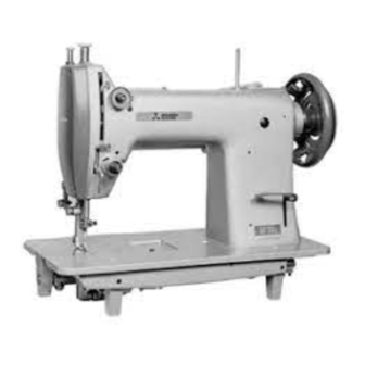
- Page 1 DOUBLE-NEEDLE LOCKSTITCH NEEDLE-FEED CORNER STITCHING AUTOMATIC UNDERTRIMMER INDUSTRIAL SEWING MACHINE MODEL LT2-2250-B1T INSTRUCTION MANUAL A180E191P02...
- Page 2 INTRODUCTION Thank you very much for purchasing Mitsubishi industrial sewing machine. Please read this instruction manual before operating the sewing machine. Please read also “Safety Manual” , “Instruction manual for Mitsubishi Limiservo X” and operate the sewing machine correctly and safely. PRECAUTION BEFORE STARTING OPERATION Safety Precautions 1 . When turning the power on, keep your hands and fingers away from the area around/ under the needle and the area around the pulley. 2 . The power must be turned off when the machine is not used, or when the operator leaves his/her seat. 3 . The power must be turned off before tilting the machine head, installing or removing the “V” belt, adjusting the machine, or replacing parts. 4 . Avoid placing fingers, hairs, obstacles, etc. near the pulley, “V” belt, bobbin winder wheel, or motor when the machine is in operation. Injury could result. 5 . Don’t put fingers into the thread take-up lever cover, around/under the needle, or pulley when the machine is in operation. 6 . If the belt cover, the finger guard, and/or the eye guard are installed, don’t operate the machine without these safety devices.
-
Page 3: Table Of Contents
CONTENTS PREPARATION FOR OPERATION ……………………………………………… 1 1 Adjustment of the needle stopping position ……………………………………… 1 USAGE PRECAUTION ……………………………………………… 2 1 Lubrication (1) ………………………………………………………………………… 2 2 Lubrication (2) ………………………………………………………………………… 2 3 Lubrication condition and adjustment on lubrication to the thread take up lever … 3 4 Adjustment of lubrication to the rotating hook ………………………………… 3 5 Precaution for the built-in type detector ………………………………………… 3 6 Installation of the belt cover ……………………………………………………… 3 7 Precaution on operation …………………………………………………………… 3 HOW TO USE ………………………………………………... -
Page 4: Preparation For Operation
PREPARATION FOR OPERATION 1 Adjustment of the needle stopping position 1 . Adjustment of “UP” position When the pedal is kicked down by heel, the machine stops at “UP” position. If marks deviate larger than 3 mm, adjust as follows. ( 1 ) Disconnect the plug (12pins) of cable from the machine head. ( 2 ) Run the machine and stop at “UP” position. ( 3 ) While holding the pulley, insert the “Adjusting tool” in the hole Ⓐ, then turn the tool. 2 . Adjustment of “Down” position When the pedal is “Neutral”... -
Page 5: Usage Precaution
USAGE PRECAUTION 1 Lubrication (1) Fill the oil reservoir with oil up to “H” mark. Oil level should be periodically checked. If oil level is found below “L” level replenish oil to “H” level. For oil, use “MC70M” specified by Mitsubishi. ※ Refer MC70M : Specific gravity (15℃ ) = 0.86 (g/cm :Viscosity (40℃ ) = 10.9 (mm Oil level mark 2 Lubrication (2) When a new sewing machine is used for the first time, or sewing machine left out of use for considerably long time is used again, replenish a suitable amount of oil to the portions indicated by arrows in the below figure. Pressure bar — 2 —... -
Page 6: Lubrication Condition And Adjustment On Lubrication To The Thread Take Up Lever
USAGE PRECAUTION 3 Lubrication condition and 4 Adjustment of lubrication to the adjustment on lubrication to rotating hook the thread take up lever ( 1 ) See dripping of oil through the oil sight window to check oiling condition during operation. ( 2 ) Adjust lubrication quantity to the thread take up lever mechanism by turning the lubrication adjustment screw. Increase Decrease Adjusting Decrease Increase screw Oil sight ... -
Page 7: How To Use
HOW TO USE 1 Installation of needles Note: Before installing the needles, be sure to turn off the power. Insert the needle upto the bottom of needle Insufficient insertion Needle distorted clamp and tighten the screw keeping the long groove side of needle face to face Long grooves are opposite 2 Winding of the bobbin thread Note: When bobbin thread is wound, keep the presser foot lifted. Adjustment ●Tension of wound thread Slack winding is recommended for polyester thread and nylon thread. -
Page 8: Selection Of The Thread
HOW TO USE 3 Selection of the thread It is recommended to use “S” twist thread in the left needle (viewed S twist thread from front), and “Z” twist thread in the right needle. When discriminate use of needle threads is impossible, use “Z” twist thread in both the needles. Z twist thread For bobbin thread, “S” twist thread as well as “Z” twist thread can be used. 4 Threading of needle threads 1 . Pass each needle thread through thread guide (A). Note: When thin slippery thread (polyester thread or filament thread, etc.) is used, Pass the thread through thread guide (B) as well. 2 . With the thread take-up lever located at the upper most position, pass each needle thread in the order shown in the following figure. - Page 9 HOW TO USE 3 . If the strong twisted thread (nylon or Tetron, etc.) is used and needle threads tension is strong (about 500gf or more), the right thread may be released from the thread tension disc. In this case, thread only the right thread as shown in the figure (keep the left thread standard). Needle thread (right) — 6 —...
-
Page 10: Adjustment Of Feed (Stitch) Length And Backstitch
HOW TO USE 5 Adjustment of feed (stitch) 6 Adjustment of the needle length and backstitch thread guide ● A djustment of feed (stitch) length…Adjust feed Adjust the needle thread guide of the needle length by turning the feed length setting dial thread tension adjuster according to the fabric, the while pushing PUSH lever. thread, and sewing condition. ● B ackstitch…Direction of stitching can be Left side Center Right side reversed by depressing the reverse sewing Needle thread lever or pushing the touch back switch. guide position Fabric Heavy Standard Light Needle... -
Page 11: Threading Of Bobbin Threads
HOW TO USE 8 Threading of bobbin threads : Adjustment of needle threads tension ( 1 ) Extend the bobbin thread above the bed. Adjust needle threads tension by turning thread tension nuts. Thread Pre-tension nut Tighten Loosen Tighten Loosen Thread tension nut Thread Opener A Adjustment of the thread take up spring 1 . Adjusting movable range of the thread take up spring ( 2 ) While holding two needle threads with your left ( 1 ) To adjust the thread take up spring ①... -
Page 12: B Timing Between The Rotating Hook Motion And The Needle Motion
HOW TO USE B Timing between the rotating hook motion and the needle motion Small gear Adjust right and left timing in the same way at the same time. Screw Ⓑ Note: If you remove the presser foot, the throat plate, and the feed dog, it makes easier to adjust. ( 1 ) Set feed length to 4.5 mm. Set Screw Ⓔ Large gear ( 2 ) Loosen two screws Ⓐ, and remove the link. Figure seen from the arrow direction ( 3 ) Loosen all screws Ⓑ, Ⓒ, Ⓓ, Ⓔ, and slide each Set screw Ⓓ hook saddle to outside. Note: At this time, don’t loosen the set screw Link Screw Ⓒ... -
Page 13: C Adjustment Of The Presser Foot Pressure
HOW TO USE ・Adjustment of the needle up and down position When the needle is lifted 2.4 mm from the lowest position, adjust the needle position so that the gap between the top of needle eye and the tip of the hook is 1.0 to 2.0 mm. ( 1 ) Remove the set screw Ⓐ. ( 2 ) Rotate one turn the needle clamp Ⓑ (Adjustment pitch is 0.6 mm), or rotate half turn the stopper Ⓓ with taking off the set screw Ⓒ (Adjustment pitch is 0.3 mm). Set screw Ⓒ ( 3 ) Return the needle clamp Ⓑ to the position before adjusting and fully tighten the set Set screw Ⓐ screw Ⓐ and Ⓒ. Stopper Ⓓ... -
Page 14: D Adjustment Of The Feed Dog Height
HOW TO USE D Adjustment of the feed dog height The feed dog height and the presser foot pressure must be adjusted according to the fabric. ◆ The fabric will be damaged if the feed dog extends too high, or if the presser foot Feed dog pressure is too large. 1.2 mm ◆ An even stitch length cannot be assured if Throat plate the feed dog is too low, or if the presser foot pressure is too small. ◆ The feed dog height is the position where the needle is at the top position. Adjustment of the feed dog height ( 1 ) Lean the machine head backward. ( 2 ) Turn the pulley by hand and stop it at the position where the feed dog rises to the maximum height. -
Page 15: E Relationship Between The Rotating Hook Motion And The Thread Take-Up Lever Motion
HOW TO USE E Relationship between the rotating Black line on boss of hook motion and the thread take-up lower shaft bearing lever motion Timing belt When the timing belt is removed for replacement, etc., the relation between the rotating hook motion and the thread take-up lever motion should be adjusted as follows: ( 1 ) Turn the pulley and stop when the thread take-up lever is lifted to the highest position. ( 2 ) Lean the machine head backward and check that the arrow (timing mark) put on the timing belt is aligned with the black line on the boss of lower shaft bearing. Timing mark (arrow) ( 3 ) If the timing mark is not in line with the black line, remove the timing belt and install Timing belt pulley it again to adjust. -
Page 16: G Relationship Between The Needle Motion And The Feed Dog Motion
HOW TO USE G Relationship between the needle Feed rock shaft crank (middle) motion and the feed dog motion Feed rock shaft crank (right) ( 1 ) Set the stitch length to “0” on the feed length setting dial. ( 2 ) Set the needle at the lowest position. Ⓐ Screw ( 3 ) Lean the machine head backward. Ⓑ Screw ( 4 ) Loosen the feed rock shaft crank set screws Link Ⓐ, Ⓑ. -
Page 17: H Operation Of The Needle Bar (Left Or Right)
HOW TO USE H Operation of the needle bar (left or right) ● T he stop lever should be set to “L” or “R” position. ( 1 ) Left needle bar stop operation Move the stop lever to “L” position to stop the left needle bar. ( 2 ) Right needle bar stop operation Move the stop lever to “R” position to stop the right needle bar. ( 3 ) Double needle bar operation To change single-needle (left or right) operation to double-needle operation, depress the push lever backward. The stop lever will automatically return to “0”... -
Page 18: J Adjustment Of The Corner Stitching Device "0" Position
HOW TO USE J Adjustment of the corner Stud rod stitching device “0” position ( 1 ) When the stop lever is set “0” position, adjust Guide pin so that the gap A and B between the cam and two hinged pins of the needle bar guide Hinged pin bracket are equal as follows. ① Rough adjustment: Needle bar guide bracket Adjust so that the center distance between two holes of the stud bolt is 115 Stop lever mm by loosening the nut and turning the stud bolt. Ⓐ Set screw Guide pin ② Fine adjustment: Loosen the guide pin set screw Ⓐ , and set so that the gap A and B between the cam and two hinged pins are equal. -
Page 19: L Installation Position Of The Feed Cam
HOW TO USE L Installation position of the feed cam ( 1 ) Set the feed length setting dial to maximum. Forward stitch ( 2 ) Turn the pulley and stop it at the position Feed length setting dial where the red mark point on the pulley meets the black mark point on the arm. ( 3 ) Move the feed cam to the position shown in the figure, and repeat the forward stitch and Backward stitch the backward stitch. Reverse sewing lever At this time, set the feed cam to the lower shaft at the position where the needle (feed dog) stops. Red mark point Pulley Feed cam Black mark point Feed connecting rod Set screw M Adjustment of forward/ backward feed length The forward/backward feed length can be adjusted... -
Page 20: N Installation Of The Movable Knife
HOW TO USE N Installation of the movable knife 1 . Initial position of the movable knife ( 1 ) Turn the pulley and stop it at the position where the needle comes to the lowest. ( 2 ) Put the cam roller into the thread trimmer cam groove by pushing the cam follower crank. ( 3 ) In this condition, turn the pulley and stop it at the position where the black mark point on the arm meets the white mark point on the pulley. Set the cam follower crank at this position with a screwdriver temporarily preventing the cam roller coming out from the cam groove. ( 4 ) Loosen bolts Ⓐ and Ⓑ. ( 5 ) Adjust so that the tip slant portion of the movable knife protrudes 0 to 0.5 mm from the fixed knife, as shown in the figure and tighten bolts Ⓐ and Ⓑ. -
Page 21: O Installation Position Of The Thread Trimmer Cam
HOW TO USE O Installation position of the thread trimmer cam ( 1 ) Adjust so that the gap between the lower shaft bushing (middle) and the bushing is 6 mm and then tighten the screw Ⓐ to the flat on the lower shaft. Reverse block ( 2 ) Place the thread trimmer cam on the end face of the bushing and the thread tension Lower shaft bushing (middle) releasing cam on the end face of the thread Screw Ⓐ trimmer cam (making the gap between each Bushing part zero), then tighten each screw. Thread tension releasing cam Feed connecting rod Set screw 6 mm Thread trimmer cam P Adjustment of the thread trimmer cam ( 1 ) Turn the pulley and stop it at the position where the needle comes to the lowest. -
Page 22: Q Adjustment Of The Holding Pressure Of The Bobbin Thread
HOW TO USE Q Adjustment of the holding pressure of the bobbin thread ( 1 ) Loosen the set screw Ⓑ for clamping the adjuster Ⓐ. (By using the socket wrench 1.5 in accessories.) ( 2 ) When the adjuster Ⓐ is moved upward, the holding pressure becomes weak. On the other hand, when the adjuster Ⓐ is moved downward, the holding pressure becomes strong. ( 3 ) Set the adjuster Ⓐ to the position where it can be gotten an adequate holding pressure of the bobbin thread. (At this time, the leaf spring Ⓒ should be located in directly below the leaf spring Ⓓ.) ( 4 ) Tighten the set screw Ⓑ. Ⓓ Weaken Ⓒ Ⓐ Strengthen Ⓑ Ⓑ Ⓐ —... -
Page 23: R Adjustment Of The Thread Tension Releasing
HOW TO USE R Adjustment of the thread tension releasing ( 1 ) Turn the pulley and stop it at the position where the needle comes to the lowest. ( 2 ) Put the cam roller into the thread trimmer cam groove by pushing the cam follower crank. ( 3 ) Turning the pulley, adjust the thread tension releasing cam so that the thread tension disc closes when the white mark point on the pulley comes in line with the black mark point on the arm. To adjust, loosen two thread tension releasing cam clamp screws Ⓐ. ( 4 ) The opening amount of the thread tension disc should be adjusted with the thread tension releasing roller Ⓑ mounted on the convex portion of the thread tension releasing cam, as shown in the figure. To adjust, loosen screws Ⓒ and pull the wire. ( 5 ) Make fine adjustments by loosening the nut Ⓓ. ( 6 ) Loosen the nut Ⓓ and make the outer casing approach to the right to increase the opening amount. White mark point Pulley Cam follower crank Thread tension ... -
Page 24: S Adjustment Of Meshing Pressure Between The Movable Knife And The Fixed Knife
HOW TO USE S Adjustment of meshing pressure between the movable knife and the fixed knife ( 1 ) Loosen the fixed knife bracket clamp bolt Ⓐ. ( 2 ) Adjust meshing pressure by turning the up and down adjusting screw Ⓑ, and tighten the bolt Ⓐ. Note: Since overpressure causes a large torque on the thread trimmer mechanism and trimming failure, adjust so that the thread can be trimmed with the minimum pressure. ( 3 ) Move the movable knife and check that the thread can be sharply trimmed. Fixed knife bracket Bolt Ⓐ Screw Ⓑ T Sharpening of the fixed knife If the fixed knife is dull, it should be sharpened as shown in the figure. -
Page 25: U Adjustment Of The Thread Trimmer With Changing The Width Between Needles
HOW TO USE U Adjustment of the thread trimmer with changing the width between needles ( 1 ) Replace the throat plate, the feed dog, the needle clamp, and the presser foot. (Since the throat plate and the feed dog are special parts designed for the thread trimming machine, be sure to use those specified by us.) ( 2 ) Lean the machine head backward. ( 3 ) Loosen two link clamp bolts Ⓙ. Cam follower crank Ⓚ ( 4 ) Remove the spring Ⓜ. Cam roller ( 5 ) Loosen hook saddle clamp screws Ⓐ and Ⓑ, Thread trimmer cam and adjust the gap between the needle and Lower shaft the hook. -
Page 26: Installation Of The Solenoid Arm
HOW TO USE V Installation of the solenoid arm Rotary solenoid ( 1 ) Install the rotary solenoid so that the gap 0 to 0.5 ㎜ between the rotary solenoid and the solenoid arm is about 0 to 0.5 mm. Note: If the gap is too large, the roller and Roller the cam follower crank interfere while rotating movement of the solenoid, which causes malfunction and result in Solenoid arm failure of the thread trimmer device. Cam follower crank W Removal procedure of the hook ( 1 ) Loosen three set screws of the small gear to Lever the hook shaft. Knife bracket ( 2 ) Remove the opener. ( 3 ) Remove the fixed knife. -
Page 27: Specifications
SPECIFICATIONS LT2-2250-B1T Specifications Model LT2-2250-B1T Specifications Medium-heavy material Application 3,000 Max. sewing speed (rpm) 0 to 7 Stitch length (mm) 33.4 Needle bar stroke (mm) 68.0 Thread take-up lever stroke (mm) 7.0 Hand Presser foot stroke (mm) Knee 13.0 Needle DP × 5 #18... - Page 28 Printed in Japan...