ILI-MB-E3
Intelligent Loop Interface-Main Board
Product Installation Document
CAUTION: STATIC SENSITIVE EQUIPMENT
!
THIS EQUIPMENT IS SENSITIVE TO STATIC ELECTRICITY. IT MAY BE DAMAGED IF NOT PROPERLY HANDLED.
TRANSPORT AND STORE THIS UNIT IN A STATIC-SHIELDING BAG.
FAILURE TO OBSERVE THIS REQUIREMENT COULD CAUSE LATENT DAMAGE TO THE EQUIPMENT WHICH
MIGHT NOT MANIFEST ITSELF UNTIL AFTER THE EQUIPMENT IS PLACED IN SERVICE.
CAUTION: DISCONNECT ALL POWER
!
REMOVE ALL SOURCES OF POWER BEFORE SERVICING, REMOVING OR INSTALLING ANY UNITS.
Section 1: Description
The ILI-MB-E3 (Intelligent Loop Interface-Main Board) is the main circuit board. When the ILI-MB-E3 is connected to the
network, it is compatible with the following systems.
®
•
E3 Series
Fire Alarm and Mass Notification System
(Autonomous Control Unit)
•
E3 Series (Expandable Emergency Evacuation) System
NOTE: The E3 Series nodes may be networked with the S3 Series System.
It provides terminals for the connection of all of the sub-assemblies. The ILI-MB-E3 sub-assembly can support the following
modules:
•
up to a total of 16 ASM-16 and/or
•
up to a total of 16 ANU-48 Remote LED Driver Modules
The ILI-MB-E3 supports the System Sensor protocol using Velociti
supports 159 detectors and 159 modules. When the unit is used in conjunction with the RPT-E3-UTP Repeater sub-assembly, J2,
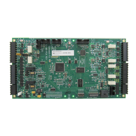
and/or J5 connected, each unit occupies one node on the Broadband network. Figure 1.1 illustrates the ILI-MB-E3 (First
Generation) module, and Figure 1.2 illustrates the ILI-MB-E3 (Second Generation) module.
NOTE: Use the Signaling Line Circuit (SLC) devices for Fire and/or E3 Series Releasing applications.
ILI-MB-E3 (First Generation)
Figure 1.1 ILI-MB-E3 (First Generation) Module
Document 9000-0579:M7
07/02/2018
ECN 18-0058
•
E3 Series Broadband System
•
E3 Series Classic System (for Fire applications only)
•
•
®
mode. In Velociti mode, each Signaling Line Circuit (SLC)
ILI-MB-E3 (Second Generation)
Figure 1.2 ILI-MB-E3 (Second Generation) Module
DACT-E3
LCD-E3 or LCD-SLP
Table of Contents

Related Manuals for Honeywell Gamewell FCI ILI-MB-E3


Summary of Contents for Honeywell Gamewell FCI ILI-MB-E3
-
Page 1: Section 1: Description
ILI-MB-E3 Intelligent Loop Interface-Main Board Product Installation Document CAUTION: STATIC SENSITIVE EQUIPMENT THIS EQUIPMENT IS SENSITIVE TO STATIC ELECTRICITY. IT MAY BE DAMAGED IF NOT PROPERLY HANDLED. TRANSPORT AND STORE THIS UNIT IN A STATIC-SHIELDING BAG. FAILURE TO OBSERVE THIS REQUIREMENT COULD CAUSE LATENT DAMAGE TO THE EQUIPMENT WHICH MIGHT NOT MANIFEST ITSELF UNTIL AFTER THE EQUIPMENT IS PLACED IN SERVICE. - Page 2 Testing/Maintenance ® and Velocit ® E3 Series i a registered trademark and CAMWorks™ is a trademark of Honeywell International Inc. ® is a registered trademark of Underwriters Laboratories, Inc. ©2018 Copyright by Honeywell International, Inc. All rights reserved. ILI-MB-E3 Product Installation Document — P/N 9000-0579:M7 07/02/2018...
-
Page 3: Section 2: Installation
Section 2: Installation 2.1 Standards The ILI-MB-E3 module complies with the following standards: Compliance - This product has been investigated and found to be in compliance with the following standards. National Fire Protection Association • NFPA 72 National Fire Alarm Code Underwriters Laboratories •... - Page 4 2.4 ILI-MB-E3 Installation Assembly Options Table 2.4.1 lists the cabinet configurations that the ILI-MB-E3 can be installed. To determine which configuration to install the ILI- MB-E3 module, identify the System your facility uses. Then, locate the configuration in the Cabinet Assembly Options column. To locate the Section that describes how to install the ILI-MB-E3 in the appropriate configuration, refer to the Installation Instructions column.
- Page 5 2.5 ILI-MB-E3 Installation Instructions Remove the ILI-MB-E3 sub-assembly from its static-shield bag, observing proper static protection measures. Visually inspect the unit for damage. If any components are damaged, notify the shipping carrier immediately. Report missing components to Gamewell-FCI Customer Service. Use the Hardware Kit provided with the unit.
- Page 6 2.5.2 ILI-MB-E3 Installed to an E3 Series Mounting Plate Configuration The ILI-MB-E3 can be installed in the following E3 Series cabinets and mounting plates. E3 Series Cabinet C E3 Series Cabinet D • E3-INCC-C Plate • E3-INCC-D Plate • E3-ILI-C Plate •...
- Page 7 2.5.3 ILI-MB-E3 Installed to the Retrofit Cabinet, Mounting Plates The ILI-MB-E3 can be installed in the following retrofit cabinet mounting plates. B-Slim Cabinet 600XL Retrofit Cabinet 7200 Cabinet B 7200 Cabinet C • B-SLIM-E3 Plate • E3-INCC-C Plate • E3-INCC-C Plate •...
-
Page 8: Section 3: Wiring
Figure 3.1.1 Signaling Line Circuits E3 Series Releasing Feature To actuate the E3 Series Releasing feature, use the signaling line circuit, Honeywell model, TC810S1000, Releasing Control Module. For additional information on the Honeywell TC810S1000 device, refer to the Honeywell, TC810S1000 Releasing Control Module Installation and Maintenance Instructions, P/N:I56-3367-000. -
Page 9: Notification Appliance Circuits
3.2 Notification Appliance Circuits The Notification Appliance Circuits (NACs) are connected from the ILI-MB-E3. The ILI-MB-E3 provides two, 24 VDC Class A, Style Z or Class B, Style Y notification appliance circuits. The E3 NAC circuits synchronize the horn and strobe outputs in the ILI-MB-E3 panels. - Page 10 3.3 ILI-MB-E3 Outputs The ILI-MB-E3 provides output for a Local Energy City Master Box, reversing polarity output for leased line connection, or Releasing Service. Table 3.3.1 lists the ILI-MB-E3 outputs. Ratings Master Box (NPL) Polarity Reversal (PL) Releasing Service Nominal Voltage 24 VDC 24 VDC 24 VDC...
- Page 11 3.5 ILI-MB-E3 Wiring Connections Figure 3.5.1 illustrates the ILI-MB-E3, (First Generation) and Figure 3.5.2 illustrates the ILI-MB-E3, (Second Generation). ILI-MB-E3 (First Generation) ILI-MB-E3 (Second Generation) SW 2 SW 1 Figure 3.5.1 ILI-MB-E3 (First Generation) Module Figure 3.5.2 ILI-MB-E3 (Second Generation) Module 3.5.1 ILI-MB-E3 Wiring Designations Table 3.5.1.1 illustrates the ILI-MB-E3 terminal designations for the First and Second Generation versions.
- Page 12 Designation Description Comments ILI-MB-E3 (First and Second Generation) Wiring Designations TB4-7 SLC 1 B- SLC 1 Style 4 / 6 / 7 Out (See Note 5) TB4-8 SLC 1 B+ SLC 1 Style 4 / 6 / 7 Out (See Note 5) TB5-1 Alarm DC NC Alarm relay contact, N/C...
- Page 13 Designation Description Comments ILI-MB-E3 (Second Generation) Wiring Designations ARCNET Termination OFF = If the ILI-MB-E3 is located in the middle of the bus or if it is not used. ON = If the ILI-MB-E3 is located at either end of the ARCNET bus. Used for ILI-MB-E3, RS-485 AUX Interface...
- Page 14 3.5.2 ILI-MB-E3 Programming Address Switch Settings Set the address using the switch, SW1. Figure 3.5.2.1 illustrates the programming address switch settings for the ILI-MB-E3. Figure 3.5.2.1 ILI-MB-E3 Programming Address Switch Settings ILI-MB-E3 Product Installation Document — P/N 9000-0579:M7 07/02/2018...
- Page 15 3.5.3 ILI-MB-E3 Wiring Diagrams 3.5.3.1 ILI-MB-E3 (First Generation) Diagram Figure 3.5.3.1.1 illustrates the wiring connections for the ILI-MB-E3 (First Generation) sub-assembly. Figure 3.5.3.1.1 ILI-MB-E3 (First Generation) Wiring Diagram ILI-MB-E3 Product Installation Document — P/N 9000-0579:M7 07/02/2018...
- Page 16 3.5.3.2 ILI-MB-E3 (Second Generation) Diagram Figure 3.5.3.2.1 illustrates the wiring connections for the ILI-MB-E3 (Second Generation) sub-assembly. Figure 3.5.3.2.1 ILI-MB-E3 (Second Generation) Wiring Diagram ILI-MB-E3 Product Installation Document — P/N 9000-0579:M7 07/02/2018...
-
Page 17: Section 4: E3 Series Configurations
Section 4: E3 Series Configurations Minimum E3 Series Configuration The minimum E3 Series configuration to use in a working system requires the following: A) ILI-MB-E3, Intelligent Loop Interface, Main Board NOTE: In a standard E3 Series configuration, install only one ILI-MB-E3 for one PM-9/PM-9G power supply connected to an FACP cabinet. -
Page 18: Section 6: Reference Documentation
S3 Series (Small Addressable Fire Alarm Control Panel System), Operating Instructions LS10121-000GF-E E3 Series for the LCD-SLP Operating Instructions Table 6.1 Reference Documentation Honeywell Gamewell-FCI 12 Clintonville Road Northford, CT 06472-1610 203.484.7161 9000-0579 | M7 | 10/18 www.gamewell-fci.com ©2018 Honeywell International Inc.