
Related Manuals for HP CodeMaster XL+ M1722A


Summary of Contents for HP CodeMaster XL+ M1722A
- Page 1 M1722A/B CodeMaster XL+ Defibrillator/Monitor User's Guide HP Part No. M1722-91908 Printed in USA November 1994 Edition 6 E1194...
- Page 2 Notice The information in this document is subject to change without notice. Hewlett-Packard makes no warranty of any kind on this material, including but not limited to, the implied warranties of merchantability and fitness for a particular purpose. Hewlett-Packard shall not be liable for errors contained herein or for incidental or consequential damages in connection with the furnishing, performance, or use of this material.
- Page 3 Packard assumes no liability for failures resulting from RF interference between HP medical electronics and any radio frequency generating equipment. THIS PRODUCT IS NOT INTENDED FOR HOME USE. This is to certify that this equipment is in accordance with the Radio Interference Requirements of Directive FTZ 1046/84.
- Page 4 Safety Symbols Monitor On (Do not confuse with 1 Joule) Off (Standby) On/Off Ground Shock hazard Caution - See operating instructions Meets IEC type BF leakage current requirements and is defibrillator protected. Meets IEC type CF leakage current requirements and is defibrillator protected.
- Page 5 Notes contain additional information on usage. NOTE represents the labels that appear on the display. TEXT represents keys on the key panel. LIGHT represents lighted indicators on the key panel.
-
Page 7: Table Of Contents
Contents Getting acquainted Operating Controls and Indications 1-1 Safety considerations 1-8 AC and DC (Battery) Operation 1-10 Battery Life 1-11 Defibrillating Defibrillating a Patient 2-1 1. Select Energy 2-2 2. Charge 2-2 3. Shock 2-3 After Using the Defibrillator 2-4 Defibrillating with Alternate Paddle Sets 2-4 Monitoring Using Leads to Monitor 3-1... - Page 8 Performing Synchronized Cardioversion 4-2 Pacing (Optional) Using the Pacer 5-2 Defibrillation During Pacing 5-4 Monitoring (Optional) and SpO Application Notes 6-1 Using SpO to Monitor a Patient 6-2 Apply the Sensor to the Patient 6-3 Troubleshooting Sensor Application 6-5 Connect the Sensor to the CodeMaster XL+ 6-6 Start Monitoring 6-7 Readings 6-7 Alarms 6-8...
- Page 9 Maintaining the Defibrillator Changing the Recorder Paper 8-1 Cleaning the Recorder Printhead 8-2 Maintaining the Battery 8-3 Battery Capacity Check 8-4 Replacing the Battery 8-5 Cleaning Exterior Surfaces 8-6 Cleaning and Sterilizing the Internal Paddles 8-7 Steam Sterilizing the Internal Paddles 8-7 Ethylene Oxide Sterilization 8-8 Supplies 8-8 Installation and Setup...
- Page 10 List of Tables Defibrillator Operating Controls 1-2 Recorder Operating Controls 1-3 Monitor Operating Controls 1-4 Pacer Operating Controls 1-5 Operating Controls 1-6 Indicator Lights 1-7 Audible Indicators 1-8 Switchless Internal Paddles Selection 2-8 Switched Internal Paddles Selection 2-9 Cardiac Monitoring Configurations 3-1 3-Wire Electrode Placement 3-2 Lead Formation 3-3 5-Wire Electrode Placement 3-3...
- Page 11 List of Tables Contents - 6...
- Page 12 The Monitor Control Panel 3-6 The Pacer Control Panel 5-1 Positioning of the Light Emitters and Photodetector 6-2 Application of the HP M1190A Reusable Sensor 6-4 Connecting the SpO Sensor to the CodeMaster XL+ 6-6 CodeMaster XL+ display with SpO...
-
Page 13: Getting Acquainted
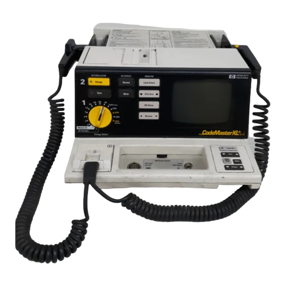
Getting acquainted This User’s Guide provides operational and basic maintenance instructions for safe use and proper care of the Hewlett-Packard M1722A/B CodeMaster XL+ defibrillator/monitor. Figure 1-1 The CodeMaster XL+ Defibrillator/Monitor Operating Controls and Indications The following figures and tables detail the controls and indications on the CodeMaster XL+ defibrillator/monitor. -
Page 14: Defibrillator Operating Controls
Getting acquainted Operating Controls and Indications Figure 1-2 Charge button Shock buttons Sync button Energy Select/power control Defibrillator Operating Controls Table 1-1 Defibrillator Operating Controls Control Description Energy Select/ Turns the instrument power on and off and selects energy level. power control Charg button... -
Page 15: Recorder Operating Controls
Getting acquainted Operating Controls and Indications Figure 1-3 Record button Mark button Recorder Operating Controls Table 1-2 Recorder Operating Controls Control Description Recor Starts and stops the recorder. Mark Mark • When the recorder is on, pressing will annotate the ECG at that point. -
Page 16: Monitor Operating Controls
Getting acquainted Operating Controls and Indications Figure 1-4 Lead Select button ECG Size button HR Alarm button Review button QRS Beeper Volume ECG Output Monitor Operating Controls Table 1-3 Monitor Operating Controls Control Description Lead Selects an ECG source to monitor. ECG Size Changes displayed ECG size. -
Page 17: Pacer Operating Controls
Getting acquainted Operating Controls and Indications Figure 1-5 Pacer On button Rate button Start/Stop button Output button Mode button Pacer Operating Controls Table 1-4 Pacer Operating Controls Control Description Pacer Turns pacer on or off. Rate Adjusts pacer rate (ppm) up or down. Start/ Starts and stops pacing. -
Page 18: Spo 2 Operating Controls
Getting acquainted Operating Controls and Indications Figure 1-6 On/Off button Alarm button Input Operating Controls Table 1-5 Operating Controls Control Description Turns pulse oximeter on or off. Activates, selects and deactivates SpO alarms. input Connector for SpO sensor or sensor adaptor cable. -
Page 19: Indicator Lights
Getting acquainted Operating Controls and Indications Figure 1-7 Charge Done Paddle Contact Indicator Sync Light AC Power Battery Charge Indicator Lights Table 1-6 Indicator Lights Indicator Description Charge Charge Done Indicates that unit is charged and ready to use. lights on key panel and on Apex paddle. -
Page 20: Safety Considerations
Getting acquainted Safety considerations Table 1-7 Audible Indicators Indicator Description Charge Done tone Sounds when instrument is charged and ready to deliver a shock. Can be disabled in setup. Auto disarm tone Sounds during the last ten seconds of the Charge Done tone. Beeps intermittently until disarmed. - Page 21 Getting acquainted Safety considerations Place the paddles in their holders and depress both Shock buttons. Leave the unit charged for 60 seconds and it will automatically disarm. • Do not leave the instrument turned on when it is not in use and it is not plugged CAUTION into AC power.
-
Page 22: Ac And Dc (Battery) Operation
Getting acquainted AC and DC (Battery) Operation • Do not rely entirely upon heart rate alarms. Rate meters on patients can continue to count the pacemaker rates during cardiac arrest or some arrhythmias. Keep pacemaker patients under close observation. • Avoid moving a charged defibrillator. If the unit is dropped, it may discharge. -
Page 23: Battery Life
Getting acquainted AC and DC (Battery) Operation Continuous recording will reduce monitoring time available when you are using the NOTE unit on battery power. When the LOW BATTERY message is displayed on the monitor, plug the unit into CAUTION AC power. From the time the LOW BATTERY message is first displayed to when the battery capacity is fully depleted (instrument shutdown), there is typically enough reserve battery capacity to provide either 30 minutes of monitoring, or five 360 joule... - Page 24 Getting acquainted AC and DC (Battery) Operation is to be stored for extended periods (more than one month) without AC power. Note on the instrument that the battery has been removed. After an extended storage period, test the battery according to the battery capacity check as described in Maintaining the Battery on page 8-3.
-
Page 25: Defibrillating
Defibrillating This chapter contains information about defibrillating a patient and using different paddle sets for defibrillating. Figure 2-1 Charge button Shock buttons Sync button Energy Select/power control Defibrillator Control Panel Defibrillating a Patient The following section describes the three steps to defibrillating a patient: Select Energy Charge Shock... -
Page 26: Select Energy
Defibrillating Defibrillating a Patient 1. Select Energy Turn the Energy Select control to the desired energy level. The defibrillator is now on. Prepare the paddles by following these steps. Remove the paddles from their holders by grasping the handles and lifting them straight up. -
Page 27: Shock
Defibrillating Defibrillating a Patient Wait for the Charge Done indicators. When the unit is armed, the monitor Delivered Energy display shows the available energy in joules. If the defibrillator does not charge, refer to Chapter 7, Troubleshooting. Resetting the Selected Energy Level To increase or decrease the selected energy level after pressing the Charge button, perform the following steps. -
Page 28: After Using The Defibrillator
Defibrillating Defibrillating a Patient After Using the Defibrillator If you want to print an Event Summary now, press Review . See Printing the Event Summary Record on page 3-8. After you use the defibrillator, perform the following steps to prepare the defibrillator for its next use. Turn the Energy Select control to Off (Standby). - Page 29 This reduces defibrillation effectiveness and can possibly burn the patient. Attach the pads adaptor cable (HP M1750A/B) to the paddle connector on the front of the defibrillator. Slide the paddle connector lock towards the front of the defibrillator to secure...
- Page 30 Defibrillating Defibrillating a Patient Attach the pads to the patient as instructed on the package. Connect the pads to the pads adaptor cable. The pads are correctly connected when the locking ring is twisted, locking the ears of the connector to the adaptor cable.
- Page 31 Defibrillating Defibrillating a Patient Attach the internal paddles adaptor cable (HP M1740A/B) to the paddle connec- tor on the front of the defibrillator. Slide the paddle connector lock towards the front of the defibrillator to secure the cable. Select correct paddle set size from Table 2-1, “Switchless Internal Paddles Selection,”...
- Page 32 Defibrillating Defibrillating a Patient Table 2-1 Switchless Internal Paddles Selection HP Part Description Number M1740A/B Internal paddles adaptor M1741A Internal paddle set, 7.5 cm diameter M1742A Internal paddle set, 6.0 cm diameter M1743A Internal paddle set, 4.5 cm diameter M1744A Internal paddle set, 2.8 cm diameter...
- Page 33 Press Charge Wait for the Charge Done indicators. Press the Shock button on the right-hand internal paddle handle. Table 2-2 Switched Internal Paddles Selection HP Part Description Number M1784A Internal paddle set, 7.5 cm diameter M1785A Internal paddle set, 6.0 cm diameter M1786A Internal paddle set, 4.5 cm diameter...
- Page 34 Defibrillating Defibrillating a Patient 2-10...
-
Page 35: Monitoring
Monitoring This chapter contains information about monitoring a patient with the CodeMaster XL+ defibrillator/monitor. This chapter also contains details of patient preparation that apply to the synchronized cardioversion and pacing procedures described later in this manual. The CodeMaster XL+ can be used for either short term or long-term cardiac monitoring. -
Page 36: Preparing The Leads For Monitoring
Monitoring Using Leads to Monitor Table 3-1 Cardiac Monitoring Configurations For this ECG In this monitoring Use this cable type... Electrode P/N source... application... PADS Pads adaptor cable: • ECG Normal M1749A M1750A/B • Synchronized Cardioversion You can use these pads for pacing, how- ever you must select LEADS as the moni-... -
Page 37: Lead Formation
Monitoring Using Leads to Monitor Table 3-3 Lead Formation Lead — 5-Wire Patient Cable Table 3-4, “5-Wire Electrode Placement,” on page 3-3 describes a typical lead-wire placement using the 5-wire patient cable. Table 3-5, “Lead Configurations,” on page 3-3 shows how the individual leads are formed using the individual leadwires. Table 3-4 5-Wire Electrode Placement Electrode... -
Page 38: Preparing The Patient
Monitoring Preparing the Patient Table 3-5 Lead Configurations Lead Leadwire Combinations LA - .5 (RA + LL) V - 1/3 (RA + LA + LL) Preparing the Patient Proper application and placement of electrodes is essential for quality ECG monitoring. Good contact between the electrode and the skin reduces the effects of motion artifact and signal interference. -
Page 39: Monitoring Electrodes
Monitoring Preparing the Patient defibrillator connector slot. If the ECG leads cable falls off or is incorrectly connected, the message LEADS OFF appears on the display. Monitoring Electrodes Using Pads Standard pads (HP1749A) allow you to monitor through the pads for defibrillation and synchronized cardioversion. -
Page 40: Monitoring
Monitoring Monitoring Monitoring Figure 3-1 Lead Select button ECG Size button HR Alarm button Review button QRS Beeper Volume ECG Output The Monitor Control Panel To monitor a patient's ECG with the CodeMaster XL+, perform the following steps. Prepare the patient for ECG monitoring. Turn the Energy Select control to the Monitor On position. -
Page 41: Heart Rate Alarms
Monitoring Heart Rate Alarms Ensure that the ECG size has been automatically adjusted for optimal size. If ECG Size you wish to reduce the ECG size, press . The "gain bar" along the left side of the display represents 1 mV of signal amplitude. Autogain allows an initial quick setup when the instrument is turned on. -
Page 42: Printing The Event Summary Record
Monitoring Printing the Event Summary Record HR alarms are automatically turned off when you press Charge NOTE Printing the Event Summary Record During defibrillator usage, the monitor stores up to 28 ECG strips of critical information called events. Events include all shocks, heart rate alarms, SpO alarms and mark events. -
Page 43: Recording
Monitoring Recording The Event Summary record is cleared each time the defibrillator is turned on and a NOTE new event occurs. This allows you to turn off the defibrillator and return later to review event information such as code statistics. Turn the defibrillator off between uses to ensure that Event Summary records are patient specific. -
Page 44: Post Shock Data
Monitoring Recording • Record on Shock • Record on Alarms The automatic recordings for both delayed and non-delayed recorder modes of operation are defined in Table 3-7, “Automatic Recordings,” on page 3-10. Table 3-7 Automatic Recordings Delayed mode Delayed mode Non- Delayed mode Event Post-event... -
Page 45: Recorder Errors
Eight Pin M14482A Twelve Pin M1783A The ECG output is also compatible with the interface to the HP central station ECG input. Do not use the ECG output to synchronize another defibrillator. (The ECG-In to NOTE ECG-Out delay is 35 milliseconds.) The connection of external equipment may increase leakage currents. - Page 46 Monitoring External Monitoring 3-12...
-
Page 47: Performing Cardioversion
Performing Synchronized Cardioversion This chapter contains information about performing synchronized cardioversion on a patient with the CodeMaster XL+ defibrillator/monitor. Refer to Chapter 3, Monitoring for information on patient preparation. Performing Cardioversion Treatment for certain arrhythmias require synchronizing a defibrillator shock with the ECG's R-wave. - Page 48 Performing Synchronized Cardioversion Performing Cardioversion Select Lead I or Lead II on the CodeMaster XL+. Plug the input end of the cable from the monitoring equipment into the ECG input plug on the CodeMaster XL+. Using Pads for Cardioversion Synchronized cardioversion can be performed with external pads. PADS can be selected as the ECG source for cardioversion because they are a reliable contact for monitoring.
- Page 49 Performing Synchronized Cardioversion Performing Cardioversion ECG mode, leads mode is recommended. Artifact induced by moving the paddles may resemble an R-wave and trigger defibrillator shock. Cardioversion can be performed with the instrument in Autogain mode. Always inspect the displayed ECG before delivering the countershock, and verify that an R-wave marker (indicating shock point) appears only with each R-wave.
- Page 50 Performing Synchronized Cardioversion Performing Cardioversion After the shock, the ECG strip will indicate whether the 100 joule test shock passed or failed. If the defibrillator does not charge, refer to Chapter 7, Troubleshooting. Applying the Paddles Prepare the paddles by performing the following steps. Remove paddles from their holders by grasping the handles and lifting straight up.
- Page 51 Performing Synchronized Cardioversion Performing Cardioversion If you must disarm the charged defibrillator (if countershock is not needed), turn the NOTE Energy Select control to Monitor On. Any stored energy will be discharged internally and the available energy on the display will return to 0. Resetting the Selected Energy Level To increase or decrease the selected energy level after the Charge button has been pressed, move the Energy Select control to the new energy level, and wait for the...
- Page 52 Performing Synchronized Cardioversion Performing Cardioversion Turn the Energy Select control to Off (Standby). Return the instrument to storage. Plug the power cord into an AC power outlet. Verify that the BATT lights are on. Clean all paddles, controls, and cables as necessary. Refer to Chapter 8, Main- taining the Defibrillator for information on cleaning the defibrillator.
-
Page 53: Pacing (Optional)
While pacing, avoid touching the gelled area of the pacing pads or WARNING the patient to prevent electrical shock. Use only HP recommended pads (M1749A) with the external pacer option. The CodeMaster XL+ delivers pacer pulses through a low-impedance multifunction pad. The CodeMaster XL+ does not pace effectively with high-impedance, pace-only electrodes. -
Page 54: Using The Pacer
Pacing (Optional) Using the Pacer The CodeMaster XL+ will pace on battery power alone. However, whenever possible, plug the CodeMaster XL+ into AC power while pacing. Using the Pacer To use the pacer, perform the following steps. Apply the pads (M1749A) as instructed on the package. Attach monitoring electrodes as instructed in Using Leads to Monitor on page 3-1. - Page 55 Pacing (Optional) Using the Pacer At this point, no pacer pulses are being delivered to the patient. The pacer must be NOTE started before the pacer pulses are delivered at the selected rate (ppm) and output (mA). Press Lead to select the best Lead for monitoring while pacing. You can only select Leads as the ECG source when the pacer is on.
-
Page 56: Defibrillation During Pacing
Pacing (Optional) Using the Pacer 14 Increase output (mA) by pressing until the beat is captured. Selecting Output an alternate lead can help you to determine capture. 15 To set the lowest possible output level to capture, decrease the current by decre- ments of 5 mA by pressing Output If the monitoring ECG lead falls off while pacing in Demand mode, the pacer will... - Page 57 Pacing (Optional) Using the Pacer After the shock, the pacer remains off. Resume pacing if it is required.
- Page 58 Pacing (Optional) Using the Pacer...
-
Page 59: Troubleshooting
Troubleshooting This chapter contains information about troubleshooting and performing diagnostics on the CodeMaster XL+defibrillator/monitor. Troubleshooting This section provides information about messages that appear on the display. Table 7-1 Failure Messages Message Possible Solutions Use a back-up defibrillator and call service. DEFIB FAILURE Use a back-up defibrillator and call service. -
Page 60: Troubleshooting The Defibrillator
Troubleshooting Troubleshooting Troubleshooting the Defibrillator Table 7-2 Defibrillator Messages Message Cause Possible Solutions Paddle set is not connected to the Attach external paddles, NO PADDLES defibrillator. internal paddles, or pads adaptor as required. Leads are not securely attached to Attach lead. LEADS OFF the patient or the cable is not con- nected to the defibrillator. - Page 61 Troubleshooting Troubleshooting Table 7-2 Defibrillator Messages Message Cause Possible Solutions DEFIB DIS- CodeMaster XL+ has internally dis- charged energy and is now dis- ARMED armed. The recorder door is open. Close the recorder door or CHECK replace the paper roll as RECORDER The recorder is out of paper.
- Page 62 Troubleshooting Troubleshooting Make sure the unit is not in synchronized shock mode. The light is on when the unit is in synchronized shock mode. If the unit discharges internally (that is, the energy display decrements slowly then beeps three times and displays the screen message DEFIB DISARMED) verify proper connections from the patient to the defibrillator.
-
Page 63: Pacer Messages
Troubleshooting Troubleshooting Troubleshooting the Pacer Table 7-3 Pacer Messages Message Cause Possible Solutions The unit detected a delivered current 1 Change pads and make PACER error. sure pads adaptor cable is FAILURE properly connected. 2 Turn the Energy Select switch to Off (Standby), then turn back to Monitor 3 Restart the pacer. -
Page 64: Troubleshooting Spo
Troubleshooting Troubleshooting Troubleshooting SpO Table 7-4 Messages Message Cause Possible Solutions The unit detected a failure in SPO2 FAILURE subsystem hardware. Press twice to This failure does not affect On/Off other parts of the instrument. power cycle the SpO2 option. If the error happens again, call for service. -
Page 65: Performing Diagnostics
Troubleshooting Performing Diagnostics Performing Diagnostics The following procedure allows complete functional inspection of the CodeMaster XL+ defibrillator/monitor. Plug the power cord into an AC outlet. Verify that the BATT lights are on. Turn the Energy Select control to the Monitor On position. The monitor trace will appear within ten seconds. -
Page 66: Operational Checks
Troubleshooting Operational Checks Keep hands clear of the paddle electrode edges. Use your thumbs WARNING to depress the Shock buttons on the paddle handles. 11 Grasp the paddle handles, and without removing the paddles from their holders, press both Shock buttons simultaneously. A brief automatic recorder run prints the delivered energy test report. -
Page 67: Every Day
Troubleshooting Operational Checks Verify that the instrument is connected to AC power, and that the BATT lights are on. Check for adequate thermal paper in the recorder. Check for ECG leads, electrodes, and adequate REDUX® electrolyte paste or defibrillator pads. Every Day Visually check AC power cord for wear. - Page 68 Troubleshooting Operational Checks Keep hands clear of the paddle electrode edges. Use your thumbs WARNING to depress the Shock buttons on the paddle handles. With the paddles in their holders, grasp the paddle handles and press the Apex paddle Shock button. Verify that the defibrillator does not discharge. Release the Apex paddle Shock button, then press the Sternum paddle Shock button.
- Page 69 Troubleshooting Operational Checks Notify Service Personnel if the ECG strip prints TEST 100J FAILED or if any of NOTE the Shock button tests fail. Disconnect the Test Load (M1781A) from the Pads Adaptor Cable (M1750A/B). Quick Pacer Functionality Test Connect the pads adaptor cable (M1750A/B) to the defibrillator and the test load (M1781A) to the adaptor cable.
-
Page 70: Every Week
Troubleshooting Operational Checks Every Week Perform the following checks on the internal paddle set every week. Check for excessive residue from sterilization on the paddle set and clean as needed. Oxidation can be an indication the paddle set is old and must be replaced. -
Page 71: Maintaining The Defibrillator
Maintaining the Defibrillator This chapter contains information about maintaining and cleaning the CodeMaster XL+ defibrillator/monitor. Changing the Recorder Paper Figure 8-1 Changing the Recorder Paper To change the recorder paper, perform the following steps. Slide the recorder door to the right of the defibrillator as shown in Figure 8-1, on page 8-1. -
Page 72: Cleaning The Recorder Printhead
Maintaining the Defibrillator Cleaning the Recorder Printhead Place a new roll of thermal paper (HP 40457C/D) in the recorder so that the paper unrolls from the top of the roll and the grid faces down as it comes out of the recorder. -
Page 73: Maintaining The Battery
Maintaining the Defibrillator Maintaining the Battery Maintaining the Battery The sealed lead-acid battery used in the CodeMaster XL+ will provide optimum life when the unit is continuously connected to AC power and fully charged after each use. To fully charge a depleted battery requires 18 hours of continuous charge time. Because it is not always possible to allow a full charge cycle between uses, the CodeMaster XL+ was designed to charge a depleted battery to 90% of its capacity in approximately two hours. -
Page 74: Battery Capacity Check
Maintaining the Defibrillator Maintaining the Battery Battery Capacity Check Perform the battery capacity check at least once every six months. If the battery is frequently depleted without adequate time for full charge cycles, perform the check more often. A new battery will provide a minimum of 2.5 hours of monitoring time. Hewlett- Packard recommends that you replace the battery when it fails to provide a minimum of 2.5 hours of monitoring time or 10 minutes of Low Battery warning time when starting from a fully charged battery. -
Page 75: Replacing The Battery
Maintaining the Defibrillator Cleaning Exterior Surfaces Fully recharge the battery by plugging the instrument into AC power for 18 hours. Verify that the BATT lights are on. The instrument is now ready to be returned to service. The battery can be permanently damaged if left uncharged for a prolonged period. CAUTION Replacing the Battery To install a new battery, perform the following steps:... -
Page 76: Cleaning And Sterilizing The Internal Paddles
Maintaining the Defibrillator Cleaning and Sterilizing the Internal Paddles Soap and water Chlorine bleach (30 ml/l water) Ammonia-based cleaners Keep the outside of the instrument clean and free of dust and dirt. Clean the paddles thoroughly to prevent build-up of dried electrolyte paste. Do Not allow any fluids to penetrate the instrument case. -
Page 77: Steam Sterilizing The Internal Paddles
Maintaining the Defibrillator Cleaning and Sterilizing the Internal Paddles Internal paddle sets can be sterilized using any of four different methods. Three of these methods use steam sterilization, the fourth method uses Ethylene Oxide (EtO). Although the internal paddle sets are constructed using the highest quality materials, the severe conditions of steam sterilization will limit their useful life. -
Page 78: Ethylene Oxide Sterilization
Maintaining the Defibrillator Supplies Ethylene Oxide Sterilization 54ºC ± 1ºC (130ºF ± 2ºF) Temperature 60% ± 20% Relative Humidity 600 mg/L ± 30 mg/L 12/88 EtO EtO Concentration 1 hour 45 minutes Exposure Time 18 hours Aeration Time Supplies The Hewlett-Packard warranty is only assured if you use Hewlett-Packard approved accessories and replacement parts. - Page 79 Maintaining the Defibrillator Supplies Trunk cable 5-wire/12-pin - IEC M1530A Lead set 5-wire - IEC M1635A Power Cords Continental Europe 8120-1692 Australia, New Zealand 8120-4464 United Kingdom, Ireland 8120-1703 Denmark 8120-2957 Italy 8120-1692 North America 8120-5213 Switzerland 8120-2296 South Africa 8120-4600 Paddles Internal paddle adaptor...
- Page 80 Maintaining the Defibrillator Supplies Pads Defibrillation/pacing pads M1749A Pads adaptor M1750A Pads adaptor (yellow) M1750B Pads adaptor test load M1781A Electrolyte (Redux®) Redux® 651-1008-050 Paper Recorder paper 40457C/D Cases Carry case M1778A Accessory pouch M1779A Wall Mount Kit Wall mount hardware M1722-80001 8-10...
-
Page 81: Installation And Setup
Installation and Setup Installation The CodeMaster XL+ is ready for operation when the following tasks have been properly performed: Install battery. Charge battery (for 24 hours). Install paper. Make sure that the paddle set connector is seated and locked. Select configuration settings; set date and time. Line Voltage Settings The defibrillator automatically adjusts to the line voltage that is supplied (from 100–... - Page 82 NOTE installation in the defibrillator. The defibrillator operates from either battery or AC power. Use only HP battery assembly M1758A. To avoid the possibility of hazardous electrical shock, unplug the WARNING instrument from the AC power source before installing or replacing the battery.
-
Page 83: Loading The Recorder Paper
Battery Installing the Battery Loading the Recorder Paper The defibrillator recorder uses two-inch wide, thermal paper (HP 40457C/D). To load the paper, refer to the procedure in “Changing the Recorder Paper” (page 7-1). Connecting Paddles and Patient Cables The defibrillator has a paddles connector for attaching pads/paddles sets and an ECG Input connector for attaching leads. - Page 84 Installation and Setup Installation The defibrillator connector accepts external paddles, external adhesive pads, or internal paddles. Connecting Paddles or Pads To connect external paddles, internal paddles, or adhesive pads to the defibrillator, perform the following steps: Slide the paddle connector lock on the paddles plug to the unlock position. To do this, push the lock towards the top of the connector.
-
Page 85: Connecting External Paddles, Adhesive Pads, Or Internal Paddles
Installation and Setup Installation Figure 1-2 Paddles plug in paddles connector Connector lock Push the lock in the direction indicated by the arrow to move the lock to the lock position (shown). Connecting External Paddles, Adhesive Pads, or Internal Paddles ECG Input Connector The ECG Input connector on the defibrillator is a 6-, 8-, or 12-pin connector, depending on the option purchased with the instrument. - Page 86 Installation and Setup Installation 3 wire = RA, LA, LL NOTE 5 wire = RA, RL, LA, LL + V (C) Connecting a Patient Cable The 3-wire or 5-wire patient cable connects to the ECG Input connector located on the front of the defibrillator, behind the carrying handle. The patient cable plug has 6- , 8-, or 12-pins.
-
Page 87: Connecting A Patient Cable
Installation and Setup Setup Figure 1-3 ECG Input connector with key slot Keyed plug of patient cable Connecting a Patient Cable Setup To configure the CodeMaster XL+ you must use the setup menus. Table 1-1, “Setup Menu 1 Settings,” on page A-9 and Table 1-2, “Setup Menu 2 Settings,” on page A- 10 list the choices you can make on the setup menus. - Page 88 Installation and Setup Setup Depress while turning the Energy Select control from Off Sync (Standby) to Monitor On. A menu will appear with the following choices. CALIBRATE DEFIB SETUP MENU 1 SETUP MENU 2 RESTORE FACTORY SETTINGS PRINT LOG TEST DEFIB TEST ECG TEST CRT TEST RECORDER...
- Page 89 Installation and Setup Setup ECG Size You must depress both sides of the key at the same time to return to the NOTE setup/diagnostic menu. SETUP MENU 2 11 To change settings in setup menu 2, select from the setup/ diagnostic menu and repeat the above steps.
- Page 90 Installation and Setup Setup Table 1-1 Setup Menu 1 Settings Setting Choices Description Time HH:MM Current time Date DD MMM YY Current date Armed Tone ON, OFF Beep on Charge done CRT Alerts ON, OFF Beep on alert message Alert Volume 3 to 15 Alerts volume Mode after CV...
- Page 91 Installation and Setup Specifications Table 1-2 Setup Menu 2 Settings Setting Choices Description ECG Trace SWEEP, SCROLL ECG trace style. Specifications Defibrillator Waveform: Damped sinusoidal (Lown). Output Energy (Delivered): 2, 3, 5, 7, 10, 20, 30, 50, 70, 100, 150, 200, 300, and 360 joules.
- Page 92 Installation and Setup Specifications Environmental Storage Conditions: -20 to 70 deg C, 90% relative humidity for 24 hours at 65 deg C, 15,000 ft altitude. Monitor Inputs: ECG may be viewed through paddles or patient cable. Lead I, II, III, or PADDLES selectable.
- Page 93 Installation and Setup Specifications Paper Size: 50 mm by 30 m (100 ft). Recorder Mode: Automatically documents events and ECG during defibrillation episodes. The recorder can be configured to run in either real time or with a six- second delay. Frequency Response: 0.5 to 40 Hz or 0.05 to 150 Hz selectable.
- Page 94 Refractory Period: 40 to 80 ppm 340 msec; 90 to 180 ppm 240 msec. (Optional) Measurement Range: 0 to 100%. Accuracy with HP M1190A sensor: 1 standard deviation, 65-80%: ±2.5%, 80- 100%: ±1.5%, resolution: 1%. Averaging: 8 beats. alarm limits — range: 100/90, 100/85, 100/80.
- Page 95 Installation and Setup Calling for Service Calling for Service United States Eastern Region Western Region Tel: 1-800-245-4406 Tel: 1-800-428-0949 Southern Region Midwestern Region Tel: 1-800-845-8374 Tel: 1-800-323-2280 Canada Eastern Region Central Region Tel: 1-800-361-9790 Tel: 1-800-387-3900 Western Region Tel: 1-800-661-5626 Other International Areas European Headquarters France...
- Page 96 Installation and Setup Calling for Service Other International Areas Netherlands Spain Hewlett-Packard Nederland Hewlett-Packard Espanolas B.V. S.A. Startbaan 16 Crta. de la Coruna 1187 XR Amstelveen km 16, 400 P.O. Box 667 Las Rozas NL-11 8O AR Amstelveen E-Madrid Tel: 20/547 69 11 Tel: 1/637 00 11 Norway Sweden...
- Page 97 Concepts (HP part number M1722-93950). You can use the SpO monitor with sensors made by other manufacturers as well as with HP sensors. For a list of approved sensors, see the Sensor Guide (HP part number M1722-93970). and SpO Hewlett-Packard is adopting the convention of referring to the SpO parameter.
-
Page 98: Positioning Of The Light Emitters And Photodetector
SpO2 Monitoring (Optional) Using SpO2 to Monitor a Patient Figure 6-1 Positioning of the Light Emitters and Photodetector For accurate measurements, the following conditions must apply: All transmitted light must pass through the extremity to the detector. The patient must have at least a minimum pulse. The light emitter and the photodetector must be opposite each other. - Page 99 HP M1900B Connector Cable. Apply the Sensor to the Patient HP supports the use of many sensors. Use the Sensor Guide to find the sensor which is best for your case. Follow the manufacturer’s guidelines for applying and using...
-
Page 100: Application Of The Hp M1190A Reusable Sensor
Application of the Reusable Sensor Figure 6-2 Application of the HP M1190A Reusable Sensor Push the sensor over the fingertip so the cable lies on the back of the hand, and secure the cable to the wrist with the wrist-strap supplied. Make sure the finger is not pinched in the end of the sensor. - Page 101 SpO2 Monitoring (Optional) Using SpO2 to Monitor a Patient path alignment and attachment. Check the application site at regular intervals — at least every two hours — and change the site if any compromise in skin quality should occur. More frequent checking may be required due to an individual patient's condition.
-
Page 102: Connecting The Spo 2 Sensor To The Codemaster Xl
SpO socket on the lower right of the CodeMaster XL+. Plug the HP M1190A sensor directly into the SpO socket of the CodeMaster XL+. The plug is keyed and is color-coded blue to distinguish it from the white ECG socket. - Page 103 SpO2 Monitoring (Optional) Using SpO2 to Monitor a Patient Start Monitoring Turn the defibrillator on, if necessary, by turning the Energy Select control to Monitor On. Press the button to display the SpO reading in the upper On/Off right corner of the display. Readings Figure 6-4 LEAD I I...
- Page 104 SpO2 Monitoring (Optional) SpO2 Alarms The pulse rate is derived from the pulse oximeter. It should correlate closely with the patient’s heart rate. Alarms Activating SpO Alarms There are three preset high/low SpO alarm limits: 100/90, 100/85 and 100/80. Press button repeatedly to cycle through the alarm options and the no- Alarm alarm option.
- Page 105 SpO2 Monitoring (Optional) SpO2 Alarms Recorder Output After an alarm event, the recorder prints a strip. The bottom of the strip shows the alarm violation, and the top of the strip shows the SpO reading. You may print an event summary record, which contains SpO information, as described in “Printing the Event Summary Record”...
- Page 106 SpO2 Monitoring (Optional) SpO2 Alarms 6-10...