Quick Links
Use, features
General features
Special features
CC1N7418en
21.06.2016
Gas Burner Controls
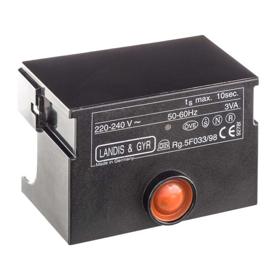
The gas burner controls are used for supervision, startup and control of
atmospheric gas burners of small to medium capacity without a fan in
intermittent operation.
The LGA... and this Data Sheet are intended for use by OEMs which integrate the
gas burner controls in their products.
The LGA are designed for startup and supervision of atmospheric gas burners in
intermittent operation. The flame is supervised with an ionization probe.
Burner controls for gas burners and gas units with or without fan
to EN 298: 1994-02 or EN 298: 1993
Undervoltage detection
Air pressure supervision with functional check of the air pressure switch during
startup and operation
LGA41.173A27 and LGA52.171B27 are suitable for use with air heaters.
Note!
Do not use for new designs.
Note!
The following burner controls can be used for new designs:
LME1...
LME2...
LME3...
LME4...
Building Technologies Division
7
418
LGA...

Related Manuals for Siemens LGA41.153A27


Summary of Contents for Siemens LGA41.153A27
- Page 1 LGA... Gas Burner Controls The gas burner controls are used for supervision, startup and control of atmospheric gas burners of small to medium capacity without a fan in intermittent operation. The LGA... and this Data Sheet are intended for use by OEMs which integrate the gas burner controls in their products.
- Page 2 Warning notes To avoid injury to persons, damage to property and the environment, the following warning notes must be observed! Do not open, interfere with or modify the unit. All activities (mounting, installation and service work, etc.) must be performed by qualified staff ...
- Page 3 Installation notes Always run the high-voltage ignition cables separate from the unit and other cables while observing the greatest possible distances Make absolutely certain that life and neutral conductors are correctly connected to terminals 1 and 2 of the burner control; otherwise, no flame signal will be generated ...
- Page 4 Electrical connection of ionization probe It is important to achieve practically disturbance- and loss-free signal transmission: Never run the detector cable together with other cables – Line capacitance reduces the magnitude of the flame signal – Use a separate cable ...
- Page 5 EAC Conformity mark (Eurasian Conformity mark) ISO 9001:2008 ISO 14001:2004 OHSAS 18001:2007 China RoHS Hazardous substances table: http://www.siemens.com/download?A6V10883536 Identification code to EN 298 - Single-stage A M C L X N - 2-stage A T C L X N Life cycle Burner controls has a designed lifetime* of 250,000 burner startup cycles which, under normal operating conditions in heating mode, correspond to approx.
- Page 6 The type references given in the table refer to gas burner controls with no base and no accessories. For ordering information for plug-in bases and other accessories, see Accessories. Article no. Type Mains voltage BPZ:LGA41.153A27 LGA41.153A27 AC 220...240 V ● ● ● BPZ:LGA52.150B17 LGA52.150B17 AC 100...110 V ●...
- Page 7 Accessories (must be ordered separately) Connection accessories Plug-in base AGK11… for small burner controls To connect the small-capacity burner controls to the burner plant. See Data Sheet N7201 Cable holders AGK66… Cable holder for plug-in base AGK11 See Data Sheet N7201 Cable holders AGK65…...
- Page 8 Technical data AC 220 V 15 %...AC 240 V +10 % General unit data Mains voltage AC 100 V –15 %...AC 110 V +10 % - Only with LGA63... AC 230 ±10 % Mains frequency 50...60 Hz ±6 % Power consumption 3 VA Perm.
- Page 9 Flame supervision Flame supervision with At mains voltage UN = AC 230 V ionization probe U Detector voltage between terminals 1 and 2 or ground (AC voltmeter Ri 10 M) Recommended detector current to ensure reliable Min. 5 µA operation Possible detector current in operation Max.
- Page 10 If the connections of live conductor (terminal 12) and neutral conductor (terminal 2) have Reversed polarity protection been mixed up, the burner control will initiate lockout at the end of the safety time (TSA). Control sequence (Times in seconds) AC 220...240 V LGA41.153A27 LGA41.173A27 LGA52.150B27 LGA52.171B27 LGA63.191A27 AC 100...110 V LGA52.150B17 Prepurge time Approx.
- Page 11 Function (cont´d) Control sequence in the If lockout occurs, the outputs for the fuel valves, the burner motor and the ignition equipment are immediately deactivated (<1 second). event of fault The lockout indication lamp changes to red and voltage is fed to terminal 10 (Alarm) for remote lockout indication.
- Page 12 Function (cont´d) Internal diagram When the switch-on command is given, power is supplied to the ignition transformer and the heating coil of the bimetal sequencing device. The bimetal bends and pushes LGA41... contact set «c, d, e» towards «f». On completion of the preignition time, the system tilts so that «e - f»...
- Page 13 Function (cont´d) Internal diagram When the switch-on command is given, the auxiliary fan starts to run. When the air pressure switch closes its contact, the heating coil of the bimetal sequencing device is LGA52... / LGA63... energized and the bimetal pushes contact set «c, d, e» towards «f» (thereby opening «f - g»).
- Page 14 Connection diagram Program sequence LGA41... 7418f01/0200 7418a04/0304 LGA52... / 63... 7418a05/0304 t3´ 7418f02/0200 Legend Fault status signal Auxiliary fan BV... Fuel valve Thermostat or pressurestat Ionization probe Safety limit thermostat Flame relay External primary fuse / pressure switch Flame signal Limit thermostat Air pressure switch Ignition transformer...
- Page 15 Dimensions Dimensions in mm LGA... Plug-in base AGK11... 41,5 2016 Siemens AG Building Technologies Division, Berliner Ring 23, D-76437 Rastatt Subject to change 15/15 Building Technologies Division CC1N7418en 21.06.2016...