Table of Contents
Table of Contents

Related Manuals for Huawei AISU


Summary of Contents for Huawei AISU
- Page 1 AISU User Manual Issue Date 2017-06-12 Huawei Technologies Co., Ltd.
- Page 2 Notice The purchased products, services and features are stipulated by the contract made between Huawei and the customer. All or part of the products, services and features described in this document may not be within the purchase scope or the usage scope. Unless otherwise specified in the contract, all statements, information, and recommendations in this document are provided "AS IS"...
-
Page 3: About This Document
About This Document About This Document Overview This document describes the antenna information sensor unit (AISU) in terms of the application scenarios and installation, configuration, and maintenance methods, providing guidance for users to operate and maintain the AISU. Intended Audience This guide is intended for: ... -
Page 4: Table Of Contents
4 Networking Modes ........................15 4.1 Regular Installation Scenario ........................15 4.2 Daisy-Chain Installation Scenario ......................18 5 Configuration Guide ........................19 5.1 AISU Used with Huawei Base Stations ....................19 5.1.1 AISU Configurations ......................... 20 Issue 02 (2017-06-12) Huawei Proprietary and Confidential... - Page 5 AISU User Manual Contents 5.1.2 AISU Maintenance and Configurations ..................28 5.2 AISU Used with Base Stations of Other Suppliers.................. 32 6 Maintenance Guide ........................33 6.1 AISU Used with Huawei Base Stations ....................33 6.1.1 Non-Alarm Maintenance ........................33 6.1.2 Alarm Maintenance ...........................
-
Page 6: Device Description
1.1 AISU Introduction The AISU measures antenna engineering parameters, including the azimuths, mechanical tilts, longitude, latitude, and altitude. The AISU is installed at the top of an antenna to perform GPS-based direction measurement. The AISU, base station, and network management system (NMS) are used together to implement the Self-Aware Antenna(SAA) solution, in which the antenna engineering parameters can be remotely queried on the NMS in real time. -
Page 7: Appearance Description
* indicates that the item is affected by the multipath environment, number of visible satellites, satellite geometric distribution, ionospheric activeness, and SBAS using and observation time. 1.3 Appearance Description The AISU contains only one AISG male connector. Issue 02 (2017-06-12) Huawei Proprietary and Confidential... -
Page 8: Description Of Aisu Sns
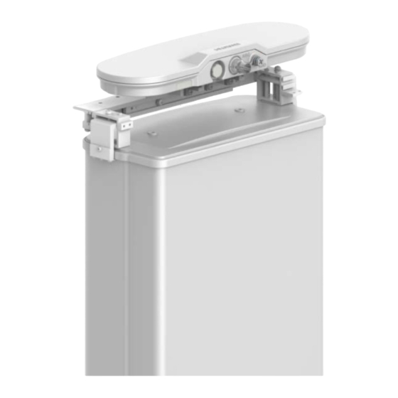
Figure 1-2 AISU on the antenna 1.4 Description of AISU SNs The device SN of the AISU consists of 19 characters. In the device SN, the third character Z indicates that the device is an AISU, and the fourth to seventh characters AISU indicates that the device is an AISU. - Page 9 AISU User Manual 1 Device Description Table 1-2 Base station versions supported by the AISU Version SRAN11.0 and SRAN9.0 SRAN10.1 Later LTE TDD Supported Supported Supported LTE FDD Supported Supported Supported Not supported Not supported Supported UMTS Not supported Not supported...
-
Page 10: Application Scenarios
If obstructions exist, block the north part of the AISU if it is installed on the northern hemisphere and block the south part of the AISU if it is installed on the southern hemisphere to ensure less impact on the AISU. -
Page 11: Recommended Scenario
The AISU should not be directly radiated by large power because the GPS receiver sensitivity is high. However, if the radiation cannot be avoided, install the AISU in compliance with the following principles to ensure the AISU measurement precision, as shown in Figure 2-3. -
Page 12: Installation With The Multipath Effect Caused By Reflection
GPS has high reception sensitivity. It is sensitive to multipath signals. Severe multipath effects have an impact on direction determination. In principles, the AISU cannot be used in reflection scenarios. If the AISU needs to be used in reflection scenarios, install it in the way shown in Figure 2-4. -
Page 13: Installation And Replacement
3.1 General Safety Precautions The precautions described in this chapter should be followed when you select measurement and test equipment for installing, operating, and maintaining Huawei products and equipment. Safety Precautions For the safety of personnel and equipment, comply with the symbols on the equipment and the safety instructions in this document when installing, operating, and maintaining Huawei products and equipment. -
Page 14: Operation Precautions
Tighten screws using tools when installing the AISU. Clean out the empty packages in the equipment room after installation is complete. 3.2 Operation Precautions Before installing or replacing an AISU, make sure that: Operations are performed by qualified installation personnel. ... -
Page 15: Installation And Maintenance Tools
Used to cut tape Insulation tape Used for waterproofing Waterproof tape Used for waterproofing 3.4 Installation Guide 3.4.1 Bracket Pre-Assembling under the Tower Step 1 Assemble the AISU bracket. Issue 02 (2017-06-12) Huawei Proprietary and Confidential Copyright © Huawei Technologies Co., Ltd. - Page 16 3 Installation and Replacement Each bracket provides two groups of installation holes: group A and group B, as shown in the following figure. During AISU installation, group B is recommended. If the AISG connector interferes with the pole, group A can be used.
-
Page 17: Installation On The Tower
Use a wrench to knock the position shown in the follow figure so that the hook is installed properly. After the bracket is installed, confirm that the bracket is secured properly. Issue 02 (2017-06-12) Huawei Proprietary and Confidential Copyright © Huawei Technologies Co., Ltd. - Page 18 Install the pre-assembled AISU onto the bracket, as shown in the following figure. For safety concern, the AISU must be bound securely using a safety rope before being carried onto the tower and installed. After the AISU is installed, remove the safety rope.
-
Page 19: Fixing The Cables
The bending radius of the cable must be at least three times the cable diameter. 3.5 AISU Replacement Remove the AISU from the bracket, as shown in the following figure. For details about how to install a new AISU after removing the old one, see section 3.4 "Installation Guide." ----End... -
Page 20: Networking Modes
NOTE An RRU can control only one AISU, and the AISU must be installed on the antenna connected to the RRU. The following figures show typical AISU application scenarios. For complex scenarios, contact Huawei engineers before using the AISU. - Page 21 AISU User Manual 4 Networking Modes Figure 4-1 AISU installed in regular mode AISU Figure 4-2 AISU connected to an external RCU AISU Issue 02 (2017-06-12) Huawei Proprietary and Confidential Copyright © Huawei Technologies Co., Ltd.
- Page 22 AISU User Manual 4 Networking Modes Figure 4-3 AISU connected to an SBT or STMA AISU Figure 4-4 AISU connected to an antenna without an RAE device AISU AISG port Issue 02 (2017-06-12) Huawei Proprietary and Confidential Copyright © Huawei Technologies Co., Ltd.
-
Page 23: Daisy-Chain Installation Scenario
For details about how to change and query the cascading mode, see Smart Antenna LTE TDD Configuration Guide. NOTE The AISU can be used only when MET antennas in LTE TDD mode are upgraded to RET antennas Figure 4-5 AISU connected to an antenna with an RAE device AISU... -
Page 24: Configuration Guide
2: Command export area 3: Command editing area 4: Parameter input area You can configure an AISU by running MML commands using any of the following methods: In Navigation Tree on the MML tab page, double-click an MML command, enter parameters in the parameter input area, and then click Exec or press F9. -
Page 25: Aisu Configurations
You can run the MOD RETPORT command to turn on the RRU power switch and set the current alarm threshold if the AISU is connected to the RET port of the RRU directly or over the external RCU or RET port of the EasyRET antenna. - Page 26 Otherwise, the system displays a failure message. Step 3 Press F9 or click Exec. If Operation succeeded is displayed in the command export area, the AISU power switch is turned on successfully. If the power switch fails to be turned on, identify causes and reset the power switch.
- Page 27 You can run the DSP RETPORT command to query the RRU power conditions and check whether the power switch for the RET port is turned on if the AISG port of the AISU is connected to the RRU RET port directly or over the external RCU or RET port of the EasyRET antenna.
- Page 28 ----End Scanning the AISUs If the AISU is working properly, you can run the SCN ALD command to scan the AISU connected to the base station. All the AISUs physically connected to the base station can be scanned, regardless of whether these AISUs are configured or not.
- Page 29 User Manual 5 Configuration Guide The SN starting with the letter Z indicates the SN of the AISU. For details about the SN, see section 1.4 "Description of AISU SNs." If the AISUs are connected in daisy-chain mode, two SNs are scanned. The correct SN must be read.
- Page 30 Control Port Cabinet No., Control Port Subrack No., and Control Port Slot No. are configured based on the configuration of Huawei base stations. If the AISU is installed in regular mode, the R0A or RET port on the RRU functions as the control port.
- Page 31 ----End Setting the AISU Properties You can run the MOD RAEDEVICEDATA command to modify the AISU properties. Procedure Step 1 In the parameter input area, enter MOD RAEDEVICEDATA in Command (F5), and then click Assist or press Enter.
- Page 32 Step 3 Press F9 or click Exec. If Operation succeeded is displayed in the command export area, the AISU properties are queried successfully. If the AISU properties fail to be queried, identify causes and query the AISU properties again. Issue 02 (2017-06-12) Huawei Proprietary and Confidential Copyright ©...
-
Page 33: Aisu Maintenance And Configurations
----End 5.1.2 AISU Maintenance and Configurations Loading AISU Software You can run the DLD ALDSW command to download the software to the AISU. The AISU software is provided by the supplier. Procedure Step 1 In the parameter input area, enter DLD ALDSW in Command (F5), and then click Assist or press Enter. - Page 34 Step 3 Press F9 or click Exec. If Operation succeeded is displayed in the command export area, the AISU software is loaded successfully. If the AISU software fails to be loaded, identify causes and load the AISU software again. ----End...
- Page 35 AISU User Manual 5 Configuration Guide If Operation succeeded is displayed in the command export area, the AISU version information is queried successfully. If the AISU configurations fail to be queried, identify causes and query the AISU version information again.
- Page 36 5 Configuration Guide ----End Resetting the AISU You can run the RST ALD command to reset the AISU. If the AISU is reset by running this command, antenna engineering parameters saved are not affected. Procedure Step 1 In the parameter input area, enter RST ALD in Command (F5), and then click Assist or press Enter.
-
Page 37: Aisu Used With Base Stations Of Other Suppliers
Step 3 Press F9 or click Exec. If Operation succeeded is displayed in the command export area, the AISU is removed successfully. If the AISU fails to be removed, identify causes and removed the AISU again. ----End 5.2 AISU Used with Base Stations of Other Suppliers Perform IOT tests before using the AISU with base stations of other suppliers and determine the AISU configuration procedure and precautions accordingly. -
Page 38: Maintenance Guide
AISU configuration and operation. Context An AISU has only one SN, which can be scanned by a control port when the AISU works in regular or daisy-chain mode. Table 6-1 describes the symptom if the SN cannot be scanned. - Page 39 Smart Antenna LTE TDD Configuration Guide. If the AISU is connected to an AIMM without the RAE function or the AISU is not connected to an AIMM, go to Step 2. Step 2 Run the SCN ALD command and check the command output.
- Page 40 ANTENNAPORT or DSP RETPORT command to check whether the AISU current consumption is normal. If yes, go to Step 1. If no, go to Step 5. Step 5 If the AISU SN cannot be scanned, check whether the AISU is properly connected to the RRU.
-
Page 41: Alarm Maintenance
Maintenance Link Failure Context If ALD Maintenance Link Failure is reported during AISU operation and maintenance, the eNodeB determines whether to clear the alarm or not based on the actual link conditions. Table 6-3 describes the maintenance link failure symptom. - Page 42 Figure 6-1 ALD Maintenance Link Failure Procedure Step 1 Run the LST RAE command and check the command output. Check whether any unnecessary AISU is configured and the AISU for which the alarm is reported needs to be configured. ...
- Page 43 User Manual 6 Maintenance Guide Step 5 Replace the AISU. After replacing the AISU, remove the abnormal AISU, and scan, add, and configure the new AISU. After 5 minutes, check whether the alarm is cleared. If the alarm is cleared, no further action is required.
- Page 44 Run the SCN ALD command to rescan the AISU. If the AISU SN is scanned, run the ADD RAE command to add the AISU. − If the added AISU SN is consistent with the former SN and the alarm is cleared, no further action is required. −...
-
Page 45: Aisu Replacement
User Manual 6 Maintenance Guide Step 3 Replace the AISU. After replacing the AISU, remove the abnormal AISU, and scan, add, and configure the new AISU. After 5 minutes, check whether the alarm is cleared. If the alarm is cleared, no further action is required. -
Page 46: A Appendix
AISU antenna information sensor unit bias tee smart bias tee AISG Antenna Interface Standards Group Satellite-Based Augmentation System SBAS Issue 02 (2017-06-12) Huawei Proprietary and Confidential Copyright © Huawei Technologies Co., Ltd. -
Page 47: Frequency Bands Of The Device Information
875–885 MHz Band VII 2500–2570 MHz 2620–2690 MHz Band VIII 880–915 MHz 925– 960 MHz Band IX 1749.9–1784.9 MHz 1844.9–1879.9 MHz Band X 1710–1770 MHz 2110–2170 MHz Issue 02 (2017-06-12) Huawei Proprietary and Confidential Copyright © Huawei Technologies Co., Ltd.