Available languages
Available languages
Quick Links
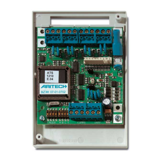
4/8-Zone DGP
M
OUNTING THE UNIT
T
T
h
h
e
e
P
P
C
C
B
B
c
c
a
a
n
n
b
b
e
e
m
m
o
o
u
u
n
n
t
t
e
e
d
d
i
i
n
n
a
a
t
t
h
h
a
a
t
t
s
s
u
u
p
p
p
p
o
o
r
r
t
t
s
s
t
t
h
h
e
e
B
B
B
B
f
f
o
o
r
r
m
m
a
a
t
t
.
.
Connections
J1
COMMS
12 VDC power supply. It is recommended that where
+
the distance between an ATS1220 and the nearest
-
device is more than 100 meters, a separate power
supply be used.
COMMS
Positive and negative data connection of the system
D+
databus.
D-
4-lift DGP or the ATS control panel, depending on
the cable used. See the ATS control panel
installation guide for details.
T
TAMP
Connect the enclosure tamper switch across these
C
terminals
open contacts.)
J2/J3
E
a
c
h
z
o
n
e
s
r
e
q
u
i
r
e
s
a
4
k
7
e
n
E
a
c
h
z
o
n
e
s
r
e
q
u
i
r
e
s
a
4
k
7
e
n
o
n
s
i
n
g
l
e
o
r
d
u
a
l
z
o
n
e
m
o
n
i
t
o
o
n
s
i
n
g
l
e
o
r
d
u
a
l
z
o
n
e
m
o
n
i
t
o
p
a
n
e
l
)
.
p
a
n
e
l
)
.
J4
+
+
1
1
2
2
V
V
D
D
C
C
s
s
u
u
p
p
p
p
l
l
y
y
a
a
n
n
d
d
o
o
p
p
e
e
n
n
c
c
o
o
c
c
o
o
n
n
n
n
e
e
c
c
t
t
i
i
o
o
n
n
t
t
o
o
A
A
T
T
S
S
1
1
8
8
1
1
0
0
,
,
A
A
T
T
S
S
v
v
i
i
a
a
1
1
0
0
-
-
w
w
a
a
y
y
c
c
a
a
b
b
l
l
e
e
s
s
u
u
p
p
p
p
l
l
i
i
e
e
d
d
w
w
i
i
t
t
o
o
u
u
t
t
p
p
u
u
t
t
s
s
a
a
r
r
e
e
a
a
v
v
a
a
i
i
l
l
a
a
b
b
l
l
e
e
w
w
i
i
t
t
h
h
8
8
-
-
w
w
w
w
a
a
y
y
a
a
n
n
d
d
8
8
/
/
1
1
6
6
-
-
w
w
a
a
y
y
o
o
u
u
t
t
p
p
u
u
t
t
c
c
a
a
r
r
d
d
s
s
a
a
m
m
e
e
D
D
G
G
P
P
)
)
L
INKS
Earth connection. Earth wires from all pieces of
equipment must be earthed at one system earth. For
further detail see the ATS control panel installation
guide.
"I
./E
. T
" J
NT
XT
AMP
UMPER
INT
Tamper switch SW4 + switch on backside SW5 of
the PCB are used (eg. in combination with ATS1644,
plastic housing).
n
n
y
y
e
e
x
x
i
i
s
s
t
t
i
i
n
n
g
g
A
A
T
T
S
S
s
s
e
e
r
r
i
i
e
e
s
s
e
e
n
n
c
c
l
l
o
o
Units can be up to 1.5 km from the
(Tamper switch requires normally
d
-
o
f
-
l
i
n
e
r
e
s
i
s
t
o
r
(
1
o
r
2
d
e
p
e
d
-
o
f
-
l
i
n
e
r
e
s
i
s
t
o
r
(
1
o
r
2
d
e
p
e
r
i
n
g
p
r
o
g
r
a
m
m
e
d
i
n
A
T
S
c
o
n
t
r
i
n
g
p
r
o
g
r
a
m
m
e
d
i
n
A
T
S
c
o
n
l
l
l
l
e
e
c
c
t
t
o
o
r
r
o
o
r
r
d
d
a
a
t
t
a
a
o
o
u
u
t
t
p
p
u
u
t
t
f
f
o
o
r
r
o
o
u
u
t
t
p
p
u
u
1
1
8
8
1
1
1
1
a
a
n
n
d
d
A
A
T
T
S
S
1
1
8
8
2
2
0
0
o
o
u
u
t
t
p
p
u
u
t
t
c
c
h
h
t
t
h
h
e
e
o
o
u
u
t
t
p
p
u
u
t
t
c
c
a
a
r
r
d
d
.
.
U
U
p
p
t
t
o
o
s
s
i
i
x
x
t
t
e
e
e
e
a
a
y
y
o
o
r
r
1
1
6
6
-
-
w
w
a
a
y
y
o
o
p
p
e
e
n
n
c
c
o
o
l
l
l
l
e
e
c
c
t
t
o
o
r
r
c
c
s
s
c
c
a
a
n
n
n
n
o
o
t
t
b
b
e
e
u
u
s
s
e
e
d
d
t
t
o
o
g
g
e
e
t
t
h
h
e
e
r
r
o
o
n
n
S
ETTINGS
EXT
s
s
u
u
r
r
e
e
DGP
DIPSWITCH SETTINGS
ADDR
ABCT
T
A,C
B
Z
ONE NUMBERING
A
A
4
4
/
/
8
8
-
-
z
z
o
o
n
n
e
e
T
T
h
h
e
e
r
r
e
e
a
a
r
r
e
e
1
1
t
t
o
o
4
4
o
o
r
r
1
1
t
t
o
o
n
d
i
n
g
n
d
i
n
g
a
a
l
l
l
l
o
o
c
c
a
a
t
t
e
e
d
d
a
a
r
o
l
t
r
o
l
s
s
h
h
o
o
u
u
l
l
d
d
b
b
e
e
p
p
d
d
a
a
t
t
a
a
b
b
a
a
s
s
e
e
.
.
C
C
o
o
n
n
t
t
r
r
o
o
l
l
p
p
D
G
P
1
D
G
P
1
D
G
P
2
D
G
P
2
t
t
D
G
P
3
D
G
P
3
a
a
r
r
d
d
s
s
D
G
P
4
D
G
P
4
n
n
D
G
P
5
D
G
P
5
a
a
r
r
d
d
s
s
(
(
4
4
-
-
D
G
P
6
D
G
P
6
t
t
h
h
e
e
D
G
P
7
D
G
P
7
N
o
t
e
1
:
T
N
o
t
e
1
:
T
p
r
o
v
i
d
e
a
d
d
p
r
o
v
i
d
e
a
d
d
LED'
S
RX
LED flashes to indicate polling data is being received on the
system databus from the ATS control panel. If the LED does
not flash the control panel is not operational or the databus is
faulty (usually cabling).
TX
LED flashes to indicate the DGP is replying to polling from the
ATS control panel. If the RX LED flashes but the TX LED
does not, it indicates that the DGP is not programmed to be
polled in the control panel or that it is addressed incorrectly.
© 2003 GE Interlogix B.V.
All Rights Reserved
ATS1210/1211/1220
4/8-Zone DGP
Tamper connections on connector J1 (T,,C) are used
for an external tamper switch (eg. In combination
with ATS1643, metal housing).
Dip switches 1 to 4 are used to identify the DGP
number.
Set switch T on if this device is the last device on the
system databus. For more details see the ATS
control panel installation guide.
Not in use
ON - ATS1811 8-way relay card or ATS1820 16-way
open collector card connected to J4.
OFF - no ATS1811 or ATS1820 connected to J4.
Use this setting also if an ATS1810 is connected to
J4.
s
s
D
D
G
G
P
P
c
c
a
a
n
n
h
h
a
a
v
v
e
e
f
f
o
o
u
u
r
r
o
o
r
r
e
e
i
i
g
g
h
h
t
t
6
6
z
z
o
o
n
n
e
e
s
s
a
a
l
l
l
l
o
o
c
c
a
a
t
t
e
e
d
d
t
t
o
o
e
e
v
v
e
e
r
r
y
y
D
D
8
8
c
c
a
a
n
n
b
b
e
e
u
u
s
s
e
e
d
d
w
w
h
h
e
e
n
n
a
a
n
n
A
A
T
T
S
S
1
1
D
D
G
G
P
P
n
n
u
u
m
m
b
b
e
e
r
r
.
.
Z
Z
o
o
n
n
e
e
s
s
n
n
o
o
t
t
a
a
v
v
a
a
r
r
o
o
g
g
r
r
a
a
m
m
m
m
e
e
d
d
a
a
s
s
t
t
y
y
p
p
e
e
0
0
(
(
z
z
o
o
n
n
e
e
d
a
a
n
n
e
e
l
l
1
1
–
–
1
1
6
6
D
D
G
G
P
P
1
7
-
3
2
D
G
P
1
7
-
3
2
D
G
P
3
3
-
4
8
D
G
P
3
3
-
4
8
D
G
P
4
9
-
6
4
D
G
P
4
9
-
6
4
D
G
P
6
5
-
8
0
D
G
P
6
5
-
8
0
D
G
P
8
1
-
9
6
D
G
P
8
1
-
9
6
D
G
P
9
7
-
1
1
2
D
G
P
9
7
-
1
1
2
D
G
P
1
1
3
-
1
2
8
D
G
P
1
1
3
-
1
2
8
D
G
P
h
e
A
T
S
1
2
1
0
/
1
2
1
1
/
1
2
2
0
c
a
n
n
h
e
A
T
S
1
2
1
0
/
1
2
1
1
/
1
2
2
0
c
a
n
n
i
t
i
o
n
a
l
z
o
n
e
s
.
i
t
i
o
n
a
l
z
o
n
e
s
.
z
z
o
o
n
n
e
e
s
s
c
c
o
o
n
n
n
n
e
e
c
c
t
t
e
e
d
d
t
t
o
o
i
i
t
t
.
.
G
G
P
P
a
a
d
d
d
d
r
r
e
e
s
s
s
s
.
.
O
O
n
n
l
l
y
y
z
z
o
o
n
n
e
e
s
s
1
1
2
2
1
1
0
0
/
/
1
1
2
2
1
1
1
1
/
/
1
1
2
2
2
2
0
0
i
i
s
s
i
i
l
l
a
a
b
b
l
l
e
e
(
(
5
5
-
-
1
1
6
6
)
)
o
o
r
r
(
(
8
8
-
-
1
1
6
6
)
)
d
i
i
s
s
a
a
b
b
l
l
e
e
d
d
)
)
i
i
n
n
t
t
h
h
e
e
Z
Z
o
o
n
n
e
e
8
8
1
1
2
2
9
9
-
-
1
1
4
4
4
4
9
1
4
5
-
1
6
0
9
1
4
5
-
1
6
0
1
0
1
6
1
-
1
7
6
1
0
1
6
1
-
1
7
6
1
1
1
7
7
-
1
9
2
1
1
1
7
7
-
1
9
2
1
2
1
9
3
-
2
0
8
1
2
1
9
3
-
2
0
8
1
3
2
0
9
-
2
2
4
1
3
2
0
9
-
2
2
4
1
4
2
2
5
-
2
4
0
1
4
2
2
5
-
2
4
0
1
5
2
4
1
-
2
5
6
1
5
2
4
1
-
2
5
6
o
t
b
e
e
x
p
a
n
d
e
d
t
o
o
t
b
e
e
x
p
a
n
d
e
d
t
o
1045037
07/2003

Related Manuals for GE Interlogix ARITECH ATS1211


Summary of Contents for GE Interlogix ARITECH ATS1211
- Page 1 PCB are used (eg. in combination with ATS1644, does not, it indicates that the DGP is not programmed to be plastic housing). polled in the control panel or that it is addressed incorrectly. © 2003 GE Interlogix B.V. 1045037 All Rights Reserved 07/2003...
- Page 2 DGP à 4/8 zones ’ ONTAGE DE L UNITE ARAMETRES DE DIPSWITCH ê ê é é ADDR Les dipswitch 1 à 4 correspondent aux numéros DGP. ABCT ONNEXIONS Mettre le switch T sur ON s’il s’agit du premier ou du dernier dispositif présent sur le bus de données du système.
- Page 3 “I .” J – – “ “ ” ” UMPER NSTELLINGEN Tamperswitch SW4 + schakelaar achterzijde print SW5 worden gebruikt (bijvoorbeeld in combinatie Controlepaneel 1 – 16 DI 8 129 - 144 met ATS1644, plastik behuizing). DI 1 17 – 32 DI 9 145 –...
- Page 4 DGP7 113 – 128 DGP15 241 – 256 ’ – ’ – Nota 1: Non è possibile ampliare l’ ATS1210/1211/1220 in modo da offrire zone addizionali. ’ – ’ – Il LED lampeggia per indicare che il bus dati del sistema riceve i dati di interrogazione dalla centrale ATS.
- Page 5 DGP de 4 a 8 zonas NSTALAÇÃO DA UNIDADE ONFIGURAÇÕES DO DIPSWITCH DO é ã é ã ú ú IGAÇÕES ú ú ç ã ç ã COMMS Fonte de alimentação de 12 Vdc. Recomenda-se que ã ã á á sempre que a distância entre um ATS1220 e o ON –...
- Page 6 Bruk denne innstillingen også hvis en ATS1810 er koblet til J4. +12 VDC-forsyning og åpen kollektor- eller datautgang for utgang tilkobling til utgangskortene ATS 1810, ATS 1811 og ATS 1820 ONENUMMERERING vha. en 10-leders kabel som følger med utgangskortet. Inntil æ...
- Page 7 – – Este LED parpadea para indicar que se están recibiendo datos de sondeo en el bus de datos del sistema desde el panel de control ATS. Si el LED no parpadea, el panel de control no está operativo o el bus de datos está...
- Page 8 1,5 km från fyrahissars-DGP:n eller från ATS - LED inte blinkar till är centralapparaten inte driftfärdig manöverpanelen, beroende på vilken kabel som eller så är något fel med databussen (vanligen används. Mer information finns i kabelfel). installationsmanualen för ATS-centralapparaten. När LED blinkar indikeras att DGP svarar på pollning TAMP Anslut kapslingens sabotagebrytare över dessa från ATS-centralapparaten.
- Page 12 Technical specifications Specifications techniques Technische specificaties Specifiche tecniche ’ ’ 10,5 - 13,8V (12V ) é é é é é ° ° é ° ° ° ° ° ° é é à à ° ° Dane techniczne Dados técnicos Tekniske spesifikasjoner Especificaciones técnicas ę...