
Related Manuals for ABB Welcome IP IPTouch 7 Series


Summary of Contents for ABB Welcome IP IPTouch 7 Series
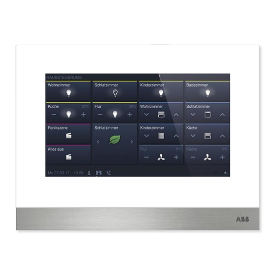
- Page 1 │ 2TMD041900D0001 25.07.2019 Product manual ABB-Welcome IP H82364-. IPTouch 7, basic H82364-.-02 IPTouch 7, basic...
-
Page 2: Table Of Contents
Table of contents Notes on the instruction manual ........................4 Safety ................................4 Intended use ..............................5 Environment ..............................12 ABB devices ............................. 12 Product description ............................13 Control elements ..........................13 Terminal description ......................... 14 Technical data ............................. 15 Mounting/Installation ............................ - Page 3 Table of contents 8.3.4 IP actuator settings .........................85 Operation ..............................94 DES page ............................94 Incoming call ............................ 96 9.2.1 Call from outdoor station/gate station ....................96 9.2.2 Call from guard unit/indoor station ....................98 9.2.3 Call from doorbell ...........................99 Intercom ............................100 9.3.1 Enter intercom page ........................
-
Page 4: Notes On The Instruction Manual
Please keep this manual in a safe place. If you pass the device on, also pass on this manual along with it. ABB accepts no liability for any failure to observe the instructions in this manual. Safety... -
Page 5: Intended Use
Intended use Intended use This device is a central control panel of the ABB-Welcome IP system and operates exclusively with components from this system. The device must only be installed in dry indoor rooms. Product range This product manual applies to the following products: Article no. - Page 6 Intended use Application case Home Community Switch IP actuator IP pushbutton OS H82364-. (Subsidiary mode) Router L AN1 H82364-. (Master mode) IP actuator Smart Access Point (Functional) Guard unit IP touch 5 OS Note H82364-. can be set to master mode and subsidiary mode. Only one indoor station can be set to master mode in the same apartment, however.
- Page 7 Intended use User password The system default is 123456. It can be used to set the following functions: ■ Card management ■ Reset user setting APP setting ■ On the "System settings", "Change password" screen, click "Change user password" to change the user password.
- Page 8 Intended use Engineering password This password is used to make engineering settings. The system default is 345678. On the "Engineering settings", "Password management" screen, click "Engineering password" to change the password. Password rule The user must change the engineering password when accessing the engineering settings for the first time.
- Page 9 Intended use Unlock password This password is used to release the lock of the outdoor station by entering the password. On the "System settings", "Change password" screen, click "Change unlock password", and enter the new password twice to change the password (3…8 digits). Password rule This password must not include continuously increasing or decreasing numbers (e.g.
- Page 10 Intended use Home screen The Home screen displays a "★" at the bottom. The system default home screen is "DES" screen. The Home screen can be set on the "Engineering setting" screen. Please see the "Device settings" chapter for more details. Extra screen The Extra screen displays "-"...
- Page 11 SD card, otherwise this SD card may fail to preform when recording or playing images. ■ ABB is no responsible for the performance of an SDHC card. IP-Cam Note The indoor station supports IP-Cam with onvif protocol (Profile S).
-
Page 12: Environment
ABB devices All packaging materials and devices from ABB bear the markings and test seals for proper disposal. Always dispose of the packing materials and electric devices and their components via an authorized collection facility or disposal company. -
Page 13: Product Description
Product description Product description Control elements Function Touch screen │13 Product manual 2TMD041900D0001... -
Page 14: Terminal Description
Product description Terminal description Function Doorbell connector LAN1 (PoE) Micro USB Upgrade connector Microphone Dismantling switch Micro SD card connector Speaker │14 Product manual 2TMD041900D0001... -
Page 15: Technical Data
Technical data Technical data Designation Value Display size 7" Resolution 1024 x 600 px Product dimensions 198.5 mm × 149.8 mm × 17 mm Operating temperature -10 °C … +55 °C PoE standard IEEE802.3 af 802.11 b/g/n: 2412...2462MHz (for United States) 2412...2472MHz (for European countries) 802.11a/n: Wireless transmission band... -
Page 16: Mounting/Installation
Mounting/Installation Mounting/Installation Warning Electric voltage! Dangerous currents flow through the body when coming into direct or indirect contact with live components. This can result in electric shock, burns or even death. – Disconnect the mains power supply prior to installation and/or disassembly! –... -
Page 17: Product Dimensions
Mounting/Installation Product dimensions Installation height 1 .5 0 m (4 .9 fe e t) │17 Product manual 2TMD041900D0001... -
Page 18: Surface-Mounted Installation
Mounting/Installation Surface-mounted installation This installation method is only suitable for H82361-., H32364-. and H82366-., and is not suitable for H82365-. Surface-mounted box 170.8 mm 60 mm Global VDE&BS&CN 120.7 mm 120.7 mm 83.3 mm 89 mm NEMA NEMA 83.3 mm Swiss NEMA&Italy │18... - Page 19 Mounting/Installation Installation │19 Product manual 2TMD041900D0001...
-
Page 20: Flush-Mounted Installation
Mounting/Installation Flush-mounted installation Pre-installation box Installation │20 Product manual 2TMD041900D0001... -
Page 21: Cavity Wall Installation
Mounting/Installation Cavity wall installation │21 Product manual 2TMD041900D0001... -
Page 22: Desktop Installation
Mounting/Installation Desktop installation This instalation is only fit for H82361-., H32364-. and H82366-., not fit for H82365-. │22 Product manual 2TMD041900D0001... -
Page 23: Dismantling
Mounting/Installation Dismantling │23 Product manual 2TMD041900D0001... -
Page 24: Commissioning
Commissioning Commissioning Initial setup This indoor station enters initial setup automatically when powered on the first time or "Clear all data" is carried out on the "Engineering settings" screen. Please see the "Clear all data" chapter for more details. 1. Select system language │24 Product manual 2TMD041900D0001... - Page 25 Commissioning 2. Accept licensing terms │25 Product manual 2TMD041900D0001...
- Page 26 Commissioning 3. Select country 4. Set date and time │26 Product manual 2TMD041900D0001...
- Page 27 Commissioning 5. Set WIFI (H82364-. only) Please see the "Network settings" chapter for more details. │27 Product manual 2TMD041900D0001...
-
Page 28: System Settings
Commissioning System settings 8.2.1 Enter system setting On the extra screen, click "System" to access the corresponding screen. │28 Product manual 2TMD041900D0001... -
Page 29: Sound
Commissioning 8.2.2 Sound On the "System settings" screen, click "Sound" to enter the sound settings. Function Touch tone setting Ringtone setting Click the drop-down list to select the ringtones for outdoor station, indoor stations, guard unit and doorbell (built-in 4 ringtones). Customized ringtone A maximum of 3 customised ringtones can be added from an SD card. -
Page 30: Language
Commissioning 8.2.3 Language On the "System settings" screen, click "Language" and select the system language. │30 Product manual 2TMD041900D0001... -
Page 31: Network Settings
Commissioning 8.2.4 Network settings WIFI settings (H82364-. only) 1. Connect WIFI Please ensure the "SSID broadcast" function is used on the router. On the "System settings" screen, click "Network settings" - "WIFI settings". The indoor station will obtain an SSID list automatically. Select a WIFI name from the SSID list and enter the password to connect to that WIFI network. - Page 32 Commissioning 2. Disconnect WIFI Select the designated WIFI name from the SSID list, click "Ignore" or "Disconnect" to disconnect the WIFI. Ignore: password needed to reconnect this WIFI. Disconnect: no password needed to reconnect this WIFI. Go back to the "Network settings" screen, the WIFI name will disappear if successful. │32 Product manual 2TMD041900D0001...
- Page 33 Commissioning IP address setting The indoor station uses DHCP to obtain an IP address from the router by default. It is also possible to set the IP address by unticking the checkbox (example below). │33 Product manual 2TMD041900D0001...
-
Page 34: Automatic Snapshot
Commissioning 8.2.5 Automatic snapshot On the "System settings" screen, click "Door Entry System" and tick the "Automatic snapshots" checkbox to enable the function. The indoor station will take 3 snapshots automatically during an incoming call. │34 Product manual 2TMD041900D0001... -
Page 35: Address Of Default Lock
Commissioning 8.2.6 Address of default lock On the "System settings" screen, click "Door Entry System", "Address of default unlock", and select the lock type (e.g. door lock) followed by the device. (e.g. OS-02). Click "OK" to save the setting. │35 Product manual 2TMD041900D0001... - Page 36 Commissioning There will be 2 icons (see below picture) activated on the "Door entry" screen. Click the first icon to release the default lock of the outdoor station. Click the second icon to release the auxiliary lock of the outdoor station by default. The other function can also be set.
-
Page 37: Program Button Setting
Commissioning 8.2.7 Program button setting On the "System settings" screen, click "Door Entry System". "Program button setting", The program button is set to "Open auxiliary lock" by default. The "Program button" function will be disabled if "Invalid" is set. The program button can be set to "Turn on the light", and you need to select IP actuator type and enter the device no. - Page 38 Commissioning On the "Door entry" screen, a light icon will be displayed. Click this icon to turn on IP actuator light. │38 Product manual 2TMD041900D0001...
-
Page 39: Card Management
Commissioning 8.2.8 Card management This indoor station can manage IC cards for IP pushbutton outdoor station. Note It is recommended that IC cards are created and maintained using local outdoor stations or management software only. On the "System settings" screen, click "Door Entry System", "Card management", and enter the user password (the system default is 123456) to access the corresponding screen. - Page 40 Commissioning Card register 1. Enter registering mode On the "Card management" screen, click "Card register", select the device and then click "Card register". The pushbutton module on the outdoor station will flash orange as a prompt to swipe an IC card.
- Page 41 Commissioning Card delete 1. Entering delete mode On the "Card management" screen, click "Card delete", select the device and then click "Card delete". The pushbutton module on the outdoor station will flash orange as a prompt to swipe an IC card.
- Page 42 Commissioning Card clear On the "Card management" screen, click "Card clear", select the device and click "Card clear". Card sync On the "Card management" screen, click "Card sync", select a source device and a target device, then click "Card sync". │42 Product manual 2TMD041900D0001...
-
Page 43: Display
Commissioning 8.2.9 Display On the "System settings" screen, click "Display" to access the corresponding screen. Function Clean screen Please see the "Clean screen" chapter for more details. Brightness Screensaver ■ "Digital clock": displays the current time at a random position on the screen. ■... -
Page 44: Date And Time
Commissioning 8.2.10 Date and time On the "System settings" screen, click "Date and time" to access the corresponding screen. Function Sync time type Tick the checkbox to sync date and time from the management software or from NTP automatically. Time and date setting Set time zone If you don’t sync date and time from management software or from NTP. -
Page 45: Monitor Settings
Commissioning 8.2.11 Monitor settings 1. Home monitor The indoor station and the camera must be on the same network. Note Video streaming between the indoor station and the 3rd party camera is unencrypted. On the "System settings" screen, click "Monitor settings", "Home monitor", then click access the corresponding screen. - Page 46 Commissioning Click to search the IP-Cams and create a camera list automatically. Select a camera from the camera list and click . Enter the name, user account and password, then click "OK". │46 Product manual 2TMD041900D0001...
- Page 47 Commissioning On the "Home monitor" screen, tick "Enable" to enable the function. With this setting, the register IP-Cam can be selected from the drop-down list on the "Door entry" screen. │47 Product manual 2TMD041900D0001...
- Page 48 Commissioning 2. Community monitor On the "System settings" screen, click "Monitor settings", "Community monitor" to access the corresponding screen. Click to download the camera list from the management software. │48 Product manual 2TMD041900D0001...
-
Page 49: App Settings
8.2.12 APP settings 1. Registering an account on the MyBuildings portal https://mybuildings.abb.com Access the link: , and click "Register". Fill in the form as required to register an account. Then activate the user account when you receive the email sent from the MyBuilding portal. - Page 50 Commissioning 2. Logging into the MyBuildings portal on the indoor station │50 Product manual 2TMD041900D0001...
- Page 51 Commissioning 3. Downloading and installing the APP Download the APP from Google Play or the APP Store via the keyword "ABB Welcome". Then install the relevant APP on mobile or tablet. Note The following snapshots used in this document were taken on the IOS system.
- Page 52 Commissioning If you do not grant the permissions, you will be able to add them later on. For example, click " " to access the settings screen on the mobile, swipe the screen down and then click to accept the permissions. │52 Product manual 2TMD041900D0001...
- Page 53 Commissioning 4. Logging into the app On the mobile phone/tablet, click to open the app, enter the user name, password and alias, tick the checkboxes to accept all the terms and conditions, then click "Log in". Note If an incorrect password is entered more than 3 times, no further attempts are permitted within certain period of time.
- Page 54 Commissioning 5. Pairing the devices On the APP "Home" screen, tap "∨", followed by "Pair devices", "IP gateway". Then tap to call up the device list, and select the alias, click "OK" to send a pairing request to the indoor station. Please write down the token ID (e.g. 1849C4BC in this case). │54 Product manual 2TMD041900D0001...
- Page 55 Commissioning On the "System settings", "APP settings" screen of the indoor station, click "Unpaired", select the relevant functions in the pop-up window, and click "Pair". │55 Product manual 2TMD041900D0001...
- Page 56 Commissioning Enter the token ID and click "OK". The indoor station will display "Paired" if successful. │56 Product manual 2TMD041900D0001...
- Page 57 Commissioning 6. Portal Sync If you have purchased a remote service, you can click "Portal sync" on the "APP settings" screen to enable the remote service immediately. │57 Product manual 2TMD041900D0001...
-
Page 58: Contacts
Commissioning 8.2.13 Contacts On the "System settings" screen, click "Contacts" to access the corresponding screen. Click "Contacts" to manage the contacts. Click "Add manually", enter a name and room number, then click "OK" to save the setting. A maximum of 64 contacts can be added. │58 Product manual 2TMD041900D0001... -
Page 59: Reset User Settings
Commissioning 8.2.14 Reset user settings On the "System settings" - "Reset settings" screen. Click "Reset user settings", enter the user password (the system default is 123456) and click "OK" to reset the user settings. │59 Product manual 2TMD041900D0001... -
Page 60: Version Information
Commissioning 8.2.15 Version information On the "System settings" screen, click "About" to view the version information. 8.2.16 Device address On the "System settings" screen, click "About" to view the address information. │60 Product manual 2TMD041900D0001... -
Page 61: Firmware Update
Commissioning 8.2.17 Firmware update It is possible to obtain the latest version on the website via scanning the QR code. Click "Documentation" - "Software" to download the file. │61 Product manual 2TMD041900D0001... - Page 62 Commissioning Note This function is only available when an SD card is inserted. On the "System settings" - "About" screen, click "Firmware update", click the file and then click "OK" to update the firmware. │62 Product manual 2TMD041900D0001...
-
Page 63: Engineering Settings
Commissioning Engineering settings 8.3.1 Enter engineering setting On the "System settings" screen, click "Engineering settings", enter the engineering password to access the settings screen. Note The settings screen will turn back to the home screen if no operations are carried out within 60 s. │63 Product manual 2TMD041900D0001... -
Page 64: Device Settings
Commissioning 8.3.2 Device settings Mode settings Function Call mode Select call mode between "Physical address" (default) and "Logical address". Mode select Please see the "Intended use" – "Application" chapter for more details. Home network port If "Master mode", ■ Wifi by default If "Subsidiary mode", ■... - Page 65 Commissioning Home screen settings Function Home screen setting ■ DES page (default) ■ CCTV Additional function on DES/Extra screen Enable/disable the function displayed on the door entry screen (e.g. call lift, call guard unit) or on the extra screen (e.g. auto unlock). │65 Product manual 2TMD041900D0001...
- Page 66 Commissioning Screen saver settings Click to change the screensaver picture from the SD card. Default guard unit Click “Address of default guard unit" and enter the address. (1…32) │66 Product manual 2TMD041900D0001...
- Page 67 Commissioning Import/export configuration file On the "Local settings" screen, click "Import/export configuration" to access the corresponding screen. Click "Export configuration file" to output a configuration file to the SD card. Click "Export System Log" to output a system log to the SD card. System log includes the events such as updating firmware, changing configuration, entering wrong password, changing password etc.
- Page 68 Commissioning Remote setting On the "Local settings" screen, the "Remote setting" function is only available on the indoor station which is set as "Master mode" or "Independent mode". If the "Remote setting" is enabled (default), this device can be set by the management software. If the "Remote setting"...
- Page 69 Commissioning Clear all data This function is only available within 120 s after the indoor station is powered on. All data including user settings and engineering settings will be reset to the factory defaults. │69 Product manual 2TMD041900D0001...
-
Page 70: Outdoor Station Settings
Commissioning 8.3.3 Outdoor station settings These settings are only supported by the pushbutton outdoor station. Outdoor station enters engineering mode Power on the outdoor station, wait until all 3 LED indicators go out. ■ ■ Press the first button on the outdoor station and hold for 10 s until all 3 LED indicators flash. The outdoor station will exit engineering mode after 5 minutes. - Page 71 Commissioning Device settings Go to the "Outdoor station settings" screen 1. Device type = GS (gate station) Device no. range is 1…32. 2. Device type = OS (outdoor station) Block no. range is 1...999, device no. range is 1...64. │71 Product manual 2TMD041900D0001...
- Page 72 Commissioning 3. Device type = 2nd OS (2nd confirmed outdoor station) [1] Location = Internal The 2nd OS is connected to the router in the apartment (see diagram below). Device no. range is 1...32. │72 Product manual 2TMD041900D0001...
- Page 73 Commissioning [2] Location = External The 2nd OS is connected to the switch outside the apartment (see diagram below). Block no. range is 1…999, the Room no. range is 01…63 + 01…32 (e.g. 0101), and the device no. range is 1...2. Note The external and internal types cannot be used in mixed scenarios in the same apartment.
- Page 74 Commissioning Lock management Go to the "Outdoor station settings" screen. Function Unlock type when swiping Set the lock to be released when swiping. ■ Default lock (default) ■ Subsidiary lock. Lock type Set the lock type for the default lock and subsidiary lock. ■...
- Page 75 Commissioning Door status detection Go to the "Outdoor station settings" screen. Function Door status detection If this function is enable, the outdoor station will send an alarm to the management software if the door is open longer than 120 s (A sensor should first be connected to the outdoor station). Tamper proof alarm If this function is enabled, the outdoor station will send an alarm to the management software if the outdoor station is removed from the wall.
- Page 76 Commissioning Sound Got to the "Outdoor station settings" screen. Function Volume of outdoor station Click "+" or "-" to adjust the ringtone volume and the voice volume on the outdoor station. Button tone Tick the checkbox to enable button tones on the outdoor station. Voice prompt ■...
- Page 77 Commissioning Lift control Only the building's outdoor station is able to use this function. The gate station and the 2nd confirmed outdoor station are not able to use this function. On the "Outdoor station settings" page, tick the checkbox to enable the function. Anti-flicker setting On the "Outdoor station settings"...
- Page 78 Commissioning Call forward Only the building's outdoor station and gate station are able to use this function. The 2nd confirmed outdoor station is not able to use this function. On the "Outdoor station settings" screen, tick the checkbox to enable the function. If this function is enabled, each incoming call from this outdoor station will be transferred to the guard unit.
- Page 79 Commissioning │79 Product manual 2TMD041900D0001...
- Page 80 Commissioning Set the function of pushbutton On the "Outdoor station settings" screen, click "Pushbutton address setting" to access the settings of the pushbuttons. "Columns of button" is only available when detecting bar pushbutton module on the outdoor station. It can be set to 1 column or 2 columns. │80 Product manual 2TMD041900D0001...
- Page 81 Commissioning Time sync setting On the "Outdoor station settings" screen. If "Sync time with management" is selected, the outdoor station will sync the time from the management software. If "Close time sync" is selected, the time and date needs to be set manually. │81 Product manual 2TMD041900D0001...
- Page 82 Commissioning Security mode and compatible mode setting On the "Outdoor station settings" screen, the outdoor station is set to "Security mode" by default (Compatible mode = off). │82 Product manual 2TMD041900D0001...
- Page 83 Commissioning Firmware update Note The outdoor station must exit engineering mode before the firmware is upgraded. On the "Outdoor station settings" screen, click "Firmware update", select the outdoor station and the file from SD card, then click "OK" to update the firmware. │83 Product manual 2TMD041900D0001...
- Page 84 Commissioning Version of outdoor station On the "Outdoor station settings" screen, view the version information. │84 Product manual 2TMD041900D0001...
-
Page 85: Ip Actuator Settings
Commissioning 8.3.4 IP actuator settings IP actuator enters Engineering mode When pressing the reset button of the IP actuator when it is powered on, the LED flashing means that the IP actuator has entered engineering mode. On the "Engineering setting" screen on the indoor station, click "IP actuator settings" to access the corresponding screen. - Page 86 Commissioning Device settings On the "IP actuator settings" screen. 1. Device type = Network IP Actuator Device no. range is 1...32. 2. Device type = Building IP actuator Block no. range is 1...999; device no. range is 1...32 │86 Product manual 2TMD041900D0001...
- Page 87 Commissioning 3. Device type = Private IP Actuator Location of IP actuator = Internal Device no. range is 1...32 (see diagram below). Co mmu n ity n e two rk Ho me n e two rk Master Switch Router D e vi ce ID : 1 ...3 2 │87 Product manual 2TMD041900D0001...
- Page 88 Commissioning Location of IP actuator = External Block no. range is 1…999; Room no. range is 01…63 + 01…32 (e.g. 0101); device no. range is 01…02 (see diagram below). Co mmu n ity n e two rk Ho me n e two rk Master Switch Router...
- Page 89 Commissioning Power lock settings On the "IP actuator settings" screen, set output mode and unlock time. │89 Product manual 2TMD041900D0001...
- Page 90 Commissioning Relay lock settings On the "IP actuator settings" screen, set Relay mode and unlock time. │90 Product manual 2TMD041900D0001...
- Page 91 Commissioning Report when unlock On the "IP actuator settings" screen, if "Report when unlock" is enabled, each unlock record from the IP actuator will be sent to the management software. │91 Product manual 2TMD041900D0001...
- Page 92 Commissioning Exit button On the "IP actuator settings" screen, set the lock type for the exit button ("Power lock" or "Relay lock"). Door status detection On the "IP actuator settings" screen, tick the checkbox to enable the function. Door open period range is 1…600 s.
- Page 93 Commissioning Firmware update The IP actuator must exit engineering mode before the firmware is upgraded. On the "Engineering settings" screen, click "IP actuator settings" - "Firmware update", select IP actuator and the file from SD card, then click "OK" to update the firmware. │93 Product manual 2TMD041900D0001...
-
Page 94: Operation
Operation Operation DES page Function Screen name Surveillance Click this icon to initialize surveillance. Please see the "Surveillance" chapter for more details. Release the default lock This icon is disabled by default. Please see the "Set the address of default lock" chapter for more details. - Page 95 Operation Function Intercom Click this icon to enter intercom page. Please see the "Intercom" chapter for more details. Call guard unit Click this icon to call the guard unit. Please see the "Call guard unit" chapter for more details. History Click this icon to view the history records.
-
Page 96: Incoming Call
Operation Incoming call 9.2.1 Call from outdoor station/gate station This indoor station displays the image as full screen by default. Click to switch to normal screen. Function Caller ID Display the image of the outdoor stations (The countdown will be displayed in the last 9 s). Click this icon to accept the call. - Page 97 Operation Function Click this icon to take a snapshot manually. Click this icon to record a video when the SD is inserted. Select the image of the outdoor station or the camera from the drop-down list. Click "+" or "-" to adjust the volume. Click this icon to end the call.
-
Page 98: Call From Guard Unit/Indoor Station
Operation 9.2.2 Call from guard unit/indoor station Function Caller ID Display the the countdown in the last 9 s. Click this icon to accept the incoming call. Click this icon to mute the ringtone on this device. Click this icon to switch between full screen and normal screen. Click "+"... -
Page 99: Call From Doorbell
Operation 9.2.3 Call from doorbell When the doorbell is pressed, this device will display for 5 s on the status bar. If the doorbell is associated with the camera, this indoor station will display the image from the camera automatically. Please see the "Home monitor" for more details. │99 Product manual 2TMD041900D0001... -
Page 100: Intercom
Operation Intercom 9.3.1 Enter intercom page In standby mode, click on the DES home screen to enter the corresponding screen. │100 Product manual 2TMD041900D0001... -
Page 101: Initiating An Intercom Call
Operation 9.3.2 Initiating an intercom call Home to home On the "Intercom contacts" screen, click "Favorite contacts", select a contact, then click initiate an intercom call. You can also click " and enter the physical address/logic address to initiate an intercom call. │101 Product manual 2TMD041900D0001... - Page 102 Operation Room to room On the "Intercom contacts" screen, click "Indoor extension". Click "Group call" to initiate a call to all indoor stations in the same apartment. Click a room (e.g. "Extension01") to initiate a call to this indoor station. │102 Product manual 2TMD041900D0001...
-
Page 103: Add To Blacklist
Operation 9.3.3 Add to blacklist There are 2 ways to add a contact to the blacklist. Option 1 On the "Intercom contacts" screen, click to access the setting. Click the contact, then select "Blocked" from the drop-down list. Option 2 On the "History"... -
Page 104: Restoring A Contact From The Blacklist
Operation 9.3.4 Restoring a contact from the blacklist On the "Intercom contracts" screen, press to access the setting. Click the contact, then select "Allowed" from the drop-down list. │104 Product manual 2TMD041900D0001... -
Page 105: Surveillance
Operation Surveillance 9.4.1 Surveillance from outdoor station In standby mode, on the DES screen, click to access the corresponding screen. │105 Product manual 2TMD041900D0001... - Page 106 Operation Function Caller ID Display the image from the outdoor station. (The countdown will be displayed in the last 9 s) End the surveillance. Release the default lock Click this icon to release the default lock of the monitored outdoor station. Program button Click this icon to release the subsidiary lock on the monitored outdoor station.
-
Page 107: Surveillance From Ip Camera
Operation 9.4.2 Surveillance from IP camera Function Caller ID Display the image from the cameras. (The countdown will be displayed in the last 9 s) End the surveillance. Click this icon to display the image of the next outdoor station or the next camera. Click here to switch between full screen and normal screen. -
Page 108: Call Guard Unit
Operation Call guard unit "Call guard unit" must be enabled before this function can be used. On the "Engineering settings" screen, click "Local settings", set "Call Guard unit" to on. Then set the address of the default guard unit. │108 Product manual 2TMD041900D0001... - Page 109 Operation On the "Door entry" screen, click to call the default guard unit. │109 Product manual 2TMD041900D0001...
-
Page 110: History
Operation History In standby mode, click on the status bar to access the corresponding screen. A maximum of 30 call records can be stored. Highlighting indicates unread status. │110 Product manual 2TMD041900D0001... - Page 111 Operation Click to play the audio or video record on the pop-up window when an SD card is inserted. Click the picture to see details on the pop up window. Click "<" or ">" to view the pictures. (a maximum of 3 pictures for each record) │111 Product manual 2TMD041900D0001...
- Page 112 Operation Click to enter the settings. Click "Delete All" to delete the entire history record. Click "Copy to SD card" to copy all snapshots to an inserted SD card. │112 Product manual 2TMD041900D0001...
-
Page 113: Voice Message
Operation Voice message Recording a new voice message In standby mode, click on the status bar, then click "New voice message" to access the corresponding screen. Click to record a voice message, click to play the voice message. A maximum of 30 voice messages can be stored. │113 Product manual 2TMD041900D0001... - Page 114 Operation Reading a voice message The indoor station will flash on the status bar if there is an unread message. In standby mode, click on the status bar, then click "Voice message" to access the corresponding screen. Click to play the voice message. │114 Product manual 2TMD041900D0001...
-
Page 115: Absence Message
Operation Absence message The indoor station allows you to leave voice messages for visitors and to record voice message from visitors. Enable "Absence message" At least one voice message must exist before this function can be used. Please see the "Voice message"... - Page 116 Operation Disable "Absence message" On the "System settings" screen, click "Door Entry System", and untick "Absence message". │116 Product manual 2TMD041900D0001...
-
Page 117: Automatic Unlock
Operation Automatic unlock "Unlock timer" should be enabled before this function can be used. On the "System settings" screen, click "Local settings", then switch "Unlock timer" to on. In standby mode, click "Unlock timer" to access the corresponding screen. │117 Product manual 2TMD041900D0001... - Page 118 Operation Click to access the settings. Click "+" to add a new setting. The system allows you to select the days of the week, with the selected options shown with highlighting. After setting the start time and end time, click "OK" to save. A maximum of 10 items is supported.
-
Page 119: Standby Unlock
Operation 9.10 Standby unlock On the extra screen, click "Unlock" to access the settings. Click and then click "+" to add a new setting. The lock type can be selected between "Door lock" and "Actuator lock". Select the lock location from the drop-down list and enter the lock name, then click "OK" to save. - Page 120 Operation Click to save and quit the setting. A maximum of 16 items is supported. In standby mode, click the lock icon to release the lock. = the lock is released = the lock is released = Door lock = Actuator lock │120 Product manual 2TMD041900D0001...
-
Page 121: Mute
Operation 9.11 Mute Mute manually Click on the status bar and select "Activate mute" to mute the ringtone immediately and is displayed on the status bar. Mute automatically Click on the status bar and select "Mute timer" to access the corresponding screen. Click and then click "+"... -
Page 122: Text Message
Operation 9.12 Text message This indoor station will flash on the status bar if there is an unread text message. On the extra screen, click "Text message" or click on the status bar to access the corresponding screen. │122 Product manual 2TMD041900D0001... - Page 123 Operation New text message On the "Text message" screen, click , enter the subject and content, then click to send this message to the management software. │123 Product manual 2TMD041900D0001...
- Page 124 Operation Inbox On the "Text message" screen, click "INBOX" to view the text messages come from management software. means an unread text message. Click to reply the text message. On the "Text message" screen, click "INBOX", then click to access the setting. Click to mark all text message as read.
- Page 125 Operation Outbox On the "Text message" screen, click "OUTBOX" to view the text messages sent to management software. means an undelivered message. Click to resend the text message. │125 Product manual 2TMD041900D0001...
-
Page 126: Call The Lift
Operation 9.13 Call the lift "Lift" must be enabled before this function can be used. On the "Engineering settings" screen, click "Local settings", then switch "Lift" to "on". On the Door Entry screen, click to call the lift to the current floor. │126 Product manual 2TMD041900D0001... - Page 127 Operation will be displayed on the status bar if successful. │127 Product manual 2TMD041900D0001...
-
Page 128: Clean Screen
Operation 9.14 Clean screen On the "System settings" screen, click "Display" , then click to access the corresponding screen. The countdown (1…30) is displayed on the screen. Any operations on the screen will be invalid. This device will exit "Clean screen" mode if an incoming call is received. │128 Product manual 2TMD041900D0001... -
Page 129: Fcc
FCC ID: 2AEBL-H82364 This device complies with Part 15 of the FCC Rules. Operation is subject to the following two conditions: (1) this device may not cause harmful interference, and (2) this device must accept any interference received, including interference that may cause undesired operation. Only operate the device in accordance with the instructions supplied. -
Page 130: Cyber Security
H8236 product, the network, its system and interfaces against any kind of security breaches, unauthorized access, interference, intrusion, leakage and/or theft of data or information. ABB Ltd and its affiliates are not liable for damages and/or losses related to such security breaches, unauthorized access, interference, intrusion, leakage and/or theft of data or information. -
Page 131: Performance And Service
Cyber security 11.2 Performance and service Network performance Type Value Ethernet 36 Mbps (53,568 packets/s) 17 Mbps (25,296 packets/s) ICMP 14 Mbps (20,832 packets/s) 22 Mbps (32,736 packets/sec) Port and service Port Service Purpose 5060 To be used by sip client. 5061 To be used by sip server 5070... -
Page 132: Deployment Guideline
Malware prevention solution The device H8236 is not susceptible to malware, because custom code cannot be executed on the system. The only way to update the software is by firmware upgrading. Only firmware signatured by ABB can be accepted. 11.7 Password rule The user needs to change the engineering password when entering the engineering settings for the first time. - Page 133 We reserve the right to at all times make technical changes as well as changes to the contents of this document without prior notice. The detailed specifications agreed to at the time of ordering apply to all orders. ABB accepts no responsibility for possible errors or incompleteness in this document.
- Page 134 Km 9 National Highway 1A , The detailed specifications agreed P.O.Box 11070 Dubai-UAE Hoang Liet, Hoang Mai, Hanoi, upon apply for orders. ABB accepts T : +971 4 3147 586 Vietnam no responsibility for possible errors F : +971 4 3401 541 T : +84 4 3861 1010 or incompleteness in this document.
- Page 135 Error! Use the Home tab to apply Überschrift 1 to the text that you want to appear here. © Copyright 2019 ABB All rights reserved │135 Product manual 2TMD041900D0001...