Table of Contents
Troubleshooting

Summary of Contents for Honeywell VXP
- Page 1 Manual No. 15372-4 January 13, 2005 System Maintenance Manual Aerospace Electronic Systems Permission has been granted to permit the U. S. Government the right to reproduce, update or change the contents of this commercial manual for Government use only.
- Page 2 This Manual is supplied to the User under license, subject to change without notice and/or recall by Honeywell at any time. The Manual at all times remains the property of Honeywell. The information contained in this Manual is considered confidential. No part of this Manual is to be copied or...
-
Page 3: Safety Precautions
The flash tube is at several atmospheres pressure and may cause injury if broken. Always wear safety shield or safety glasses when testing the Strobex. Warning Do not look directly into the Strobex or into the FasTrak LEDs. Permanent eye damage could occur. VXP System Maintenance Manual... - Page 4 Honeywell...
-
Page 5: Table Of Contents
2.3 VXP System Checkout ........ - Page 6 3.2.1 VXP Manual Operation ........
- Page 7 3-1. VXP System Block Diagram ........3-1...
- Page 8 Honeywell...
- Page 9 4-9. Common VXP System Problems ......4-13 4-10. VXP Error and Action Codes ....... . 4-16 4-11.
- Page 10 Honeywell...
-
Page 11: Chapter 1. Introduction
However, a permanent configuration is available that can serve to monitor aircraft performance at preset intervals. The main components of the VXP are the Acquisition Unit, the Display Unit, which is a small Pentium notebook computer, the CompactFlash Card Adapter, Zio! USB CompactFlash Card Reader/Writer, USB Floppy Disk Drive, and the printer. -
Page 12: System Physical Description
Introduction 1.2 SYSTEM PHYSICAL DESCRIPTION The VXP system main components are shown in Figures 1-1, 1-2, 1-3 and 1-4. The system accessories are shown in Figure 1-5, and the system interconnect cables in Figure 1-6. The system components are listed in Table 1-1, and the cables in Table 1-2. -
Page 13: Display Unit
Introduction Figure 1-2. Display Unit Figure 1-3. Thermal Printer Figure 1-4. USB Floppy Disk Drive VXP System Maintenance Manual... -
Page 14: Compactflash Card And Adapter
Introduction Figure 1-5. CompactFlash Card and Adapter Figure 1-6. Zio! USB CompactFlash Card Reader/Writer and USB Extension Cable Honeywell... -
Page 15: System Accessories
Introduction Figure 1-7. System Accessories VXP System Maintenance Manual... -
Page 16: System Cables
Introduction Figure 1-8. System Cables Honeywell... - Page 17 Introduction Table 1-1. VXP Major Components Part No. Nomenclature Purpose Quantity 15160 Acquisition Unit Acquires and processes data (AU) from the various sensors throughout the aircraft. 15370 Display Unit (DU) A small notebook PC, used to display data and control data 17330 acquisition.
- Page 18 Introduction Table 1-1. VXP Major Components Part No. Nomenclature Purpose Quantity 13955 Accelerometer (ICP) Converts acceleration into an analog voltage signal. 610-199 Printer paper Spare paper rolls for thermal printer. 610-527 Carrying case Allows for all-in-one portability. Protects when not in use.
-
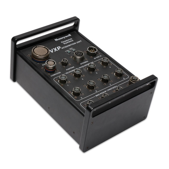
Page 19: Acquisition Unit
Operating Temperature Range -30°C to +60°C Storage Temperature Range -55°C to +85°C Processing 32-bit microprocessor Digital Signal Processor (DSP) RISC based Time Processor Unit (TPU) Memory 6 MB DRAM 2 MB FLASH 2 MB SRAM VXP System Maintenance Manual... - Page 20 0 - 20 Hz to 0 - 75 KHz Frequency Resolution 400 to 51,200 lines Window Types Flat-top, Hanning, Kaiser-Bessel, Uniform Simultaneous Channels 4 vibration 1 azimuth Dynamic Range > 90 dB Averaging Linear, Peak hold Amplitude Accuracy ±2% 1-10 Honeywell...
-
Page 21: Display Unit
4.5 lbs. (2.1 kg) Input Power 15 Vdc @ 25 W nominal 16 Vdc @ 25 W nominal Power Source VXP AU via 902-15371 cable or VXP AU via 902-17317 cable or accessory AC adapter (provided) accessory AC adapter (provided Operating Temperature -30°C to +60°C... -
Page 22: Printer
The printer is configured using three internal DIP switches, which must be set properly in order for the printer to work with the VXP system. Refer to section 2.2.3.2 for information on checking and setting the DIP switches. -
Page 23: Zio! Usb Compactflash Card Reader/Writer
RAM and 1MB of free hard drive space 1.2.5 Zio! USB CompactFlash Card Reader/Writer The VXP system includes a Zio! USB Compact Flash Card Reader/Writer that is used to transfer application and configuration files to the system (upload) and data files from the system (download) for storage. -
Page 24: Usb Floppy Disk Drive
Introduction 1.2.6 USB Floppy Disk Drive The VXP system includes a floppy disk drive that is used to transfer application and configuration files to the system (upload) and data files from the system (download) for storage. The USB Floppy Disk Drive is compatible with 1.44MB high density diskettes and PC formatted 720KB double density diskettes. -
Page 25: Fastrak Day/Night Optical Tracker
-55° to +85° C 1.2.8 Strobex The Strobex is a hand-held strobelight used primarily for tail rotor blade tracking on the VXP. Its flash rate is controlled by the Acquisition Unit and is a multiple of the incoming Photocell pulse rate. -
Page 26: Photocell
10-30 Vdc at less than 25mA (exclusive of load). 10% maximum ripple Response Time 300 microsecond (0.3 millisecond) duration (independent of signal strength) Light Beam Visible red (650 nm) Operating Temperature Range -20° to +70° C (-4° to +158° F) 1-16 Honeywell... -
Page 27: Operating Environment
Introduction 1.3 OPERATING ENVIRONMENT The VXP can be operated either during the day or at night. Testing can be done using a standard 24-32 Vdc power supply. There are no specific environmental restrictions for this equipment. Please see the Safety Precautions page immediately following the Table of Contents for information on the safe operation of this equipment. - Page 28 Introduction 1-18 Honeywell...
-
Page 29: Chapter 2. Preparation For Use
Optional equipment is listed in the introduction. Since the VXP can be attached to a variety of aircraft, there is no set installation procedure. Each aircraft application has specific software with on-line help that includes information on how and where to connect the various sensors that may be needed. -
Page 30: Software Loading
2.2.2.1 DU Software Loading Procedure The software that provides the user interface to the VXP Operational Program (OP) is executed on the DU, and is called the Display Program (DP). It should not be necessary to load the DP, because the DU is provided with the software installed. -
Page 31: Au Software Loading Procedure
VXP Operational Program (OP), SmartCharts, balance models, data collection routes, and other configuration files. Each time the VXP is used on a new aircraft type, an AP specific to that aircraft must be loaded into the AU. Each AP has a unique name and part number. -
Page 32: Printer Preparation
Preparation for Use 2.2.3 Printer Preparation Although any Windows printer can be used with the VXP, the usual configuration for testing aircraft includes a small Seiko thermal printer. The correct paper to use with this printer can be ordered from Chadwick Helmuth. The part number is 610-199. -
Page 33: Printer Dip Switch Settings
ON: Busy Control = H/W Busy OFF: Setting Command = ON: International OFF: Baud Disable OFF: Printing ON: Character ON: Rate ON: Density ON: Set ON: Select ON: = 100% OFF: = USA ON: = 9600 bps VXP System Maintenance Manual... -
Page 34: Vxp System Checkout
The checks listed in this paragraph must be performed to determine that all systems are operating correctly. 2.3.1 Preparation and Checkout Procedure Table 2-2 is a detailed checklist for preparing the VXP for use. The system checks should be performed in the order listed. Table 2-2. Preparation and Checkout Procedure... - Page 35 DP Software Turn on the DU, and wait for the main desktop to appear. Launch the VXP DP by touching the VXP icon on the desktop twice in rapid succession, and verify that the DP starts. Once the DP starts, continue with the remaining checks. If the VXP icon is not present or the DP fails to start, refer to section 2.2.2.1 for...
- Page 36 Preparation for Use Honeywell...
-
Page 37: Chapter 3. System Operations
This manual only provides instructions for completing functional tests of the VXP. 3.1 SYSTEM DESCRIPTION The major components of the VXP system are described here. A system block diagram is shown in Figure 3-1. Figure 3-1. VXP System Block Diagram... -
Page 38: Acquisition Unit
The printer is shown in Figure 1-3. The VXP can also be used with a standard parallel printer, such as an inkjet or laser printer. This would have to be connected to the DU using the parallel port on a Panasonic port replicator, or the USB port on the DU. -
Page 39: Fastrak Optical Tracker
It emits visible-red sensing beams to make alignment easy. 3.1.8 Accelerometer The VXP system is compatible with a variety of accelerometers, including Charge Mode and Low Impedance Voltage Mode (LIVM) types. Accelerometers employ a crystal and a mass to convert acceleration into an analogous output signal. -
Page 40: Charge Mode Accelerometers
Unit. 3.1.11 Cables All of the cables necessary to operate the VXP system are included in the kit. Each separate cable attaches to a specific component and the Acquisition Unit. The Strobex cable is permanently attached to the Strobex, and also connects directly to the Acquisition Unit. -
Page 41: Vxp Operation
System Operations 3.2 VXP OPERATION The VXP is operated manually using the VXP Display Program and notebook computer or other Windows PC. If the touch screen is being used, items may be selected by touching the screen with a stylus or other object with a rounded tip. -
Page 42: Monitor Mode
The VXP can be configured to continuously collect vibration data in flight by uploading a monitor route in a vmssetup.cfg file to the AU. If the VXP has been configured this way, the vibration monitor will run under the following conditions: Power is applied to the AU. -
Page 43: Vxp Log Files
Log files may be viewed as follows: Apply power to the system. After the main desktop appears on the DU, launch the VXP DP by double clicking on (or touching twice in rapid succession) the VXP icon . The Start Up dialog box will appear. -
Page 44: Clear Logs Window
Log files or the database may be cleared as follows: Apply power to the system. After the main desktop appears on the DU, launch the VXP DP by double clicking on (or touching twice in rapid succession) the VXP icon . -
Page 45: Chapter 4. Maintenance
Chadwick-Helmuth for repair. 4.2.1 Inspections The VXP should be inspected each time it is used. At the minimum, a thorough inspection of all of the components should be performed every 12 months. Following are tables showing the routine inspection procedures for each of the major components. -
Page 46: Acquisition Unit
Clean if dirty. If scratched, return to Chadwick-Helmuth for repair. Inspect trigger switch handle for condition Return to Chadwick-Helmuth for repair. and proper operation. CAUTION: If the Strobex is accidentally dropped or damaged, inspect in accordance with Table 4-4. Honeywell... -
Page 47: Fastrak Optical Tracker
NOTE: The infrared light-emitting diodes (LEDs) are factory aligned and may appear to be pointing randomly. This configuration is normal. VXP System Maintenance Manual... -
Page 48: Photocell
Chapter 5. 4.3 FUNCTIONAL TESTS This section contains instructions to test the VXP system performance parameters. If a test step fails, refer to the “Troubleshooting Guide” in Section 4.4 to locate the faulty component. The functional tests provide a high confidence level that the instrument is operating properly and within specifications. -
Page 49: Power-Up Self-Test
The fault log will be displayed on the screen. To print the fault log on the serial printer: Pull down the File menu and select the AU printer, or click on the Print Icon the left side of the display. Select Fault Log from the Print Menu. VXP System Maintenance Manual... -
Page 50: Balance Test
Maintenance The fault log file will be printed on the serial printer. See section 4.4 for an explanation of VXP error messages. Since the vxpfault.log file is an ASCII text file, it can also be viewed with any text editor, such as Notepad. -
Page 51: Functional Test Limits For Accelerometers And Velocimeters
Table 4-8. Functional Test Limits for Accelerometers and Velocimeters using Model 11A Calibrator Sensor Type/ Magnitude Phase Sensitivity Part No. (ips) (hrs:min) Accelerometer (ICP) 10 mV/G 1.00 ±0.15 6:00 ±0:30 906-13728 906-13925 906-13955 Accelerometer (High 100 pC/G 0.055 ±0.008 6:00 ±0:30 Temp) 906-7569A VXP System Maintenance Manual... -
Page 52: Spectrum Test
3.2.1 for detailed instructions on manual operation. In the Measurements Only menu, click on the SPECTRUM MEAS ONLY button. Click on the More button beneath the spectrum display window. Note that the More button toggles between More and Less. Figure 4-4. Spectrum Test Options Honeywell... -
Page 53: Typical Spectrum Results
17. Verify that the RPM display in the upper right corner of the Spectrum Meas Only window indicates 900 ±10. 18. Repeat the preceding steps as needed to test all vibration and azimuth channels. Figure 4-5. Typical Spectrum Results VXP System Maintenance Manual... -
Page 54: Strobex Track Test
Assemble the test set-up as shown in Figure 4-1 using the appropriate sensors and cables. Install a photoprobe in the magnetic pickup hole in the front of the calibrator and lock down with the retaining nut. Remove the interrupter screws from the calibrator disk. 4-10 Honeywell... -
Page 55: Fastrak Test
In the Measurements Only menu, click on the Bal Meas Only button. 10. In the Bal Meas Only menu (Figure 4-3), enter the following settings: • Select AZIMUTH 1 in the AZ CH: pull down window. VXP System Maintenance Manual 4-11... -
Page 56: Special Overlays
4.3.7.1 Special Overlays The figure below can be used to construct the special overlays needed for the FasTrak test. Copy the overlay, and cut the circle to fit the strobe disk of the Model 11A Calibrator. Figure 4-7. Special Overlay 4-12 Honeywell... -
Page 57: Troubleshooting Guide
If a component fails and needs repair, it must be returned to Chadwick-Helmuth. The second table lists the error codes for the VXP system and the action codes for clearing the errors. The third table shows the action codes, and the specific actions that each code requires. If the VXP displays an error message not shown in the table, it must be returned to Chadwick- Helmuth for repair. -
Page 58: Vxp Troubleshooting
Maintenance Table 4-9. Common VXP System Problems (Continued) Symptom Probable Cause Corrective Action The serial printer fails to print The serial cable is not Connect the serial cable. from the AU. connected. The DIP Switch settings Refer to Section 2.2.3.2 for are incorrect. -
Page 59: Error Codes
Maintenance 4.4.2.1 Error Codes Table 4-10 contains error codes that the VXP System might return, along with codes indicating the severity, overwrite mode and error recovery action codes. The Severity Levels given in the Level column of Table 4-10 are: Informational: This log entry may occur during normal system operation. - Page 60 Maintenance Table 4-10. VXP Error and Action Codes Error Over- Code Component Condition Level write Recovery Action 00001 Monitor Memory Usage none A001 00002 Database Memory Usage none A002 00003 P/U Message none none 10101 EPROM Checksum user A003 101xx...
- Page 61 Maintenance Table 4-10. VXP Error and Action Codes (Continued) Error Over- Code Component Condition Level write Recovery Action 11201 112xx Bad Packet internal A004 11202 (DU Comm) Packet Length Invalid internal A004 11203 Packet ID Invalid internal A004 11204 Receive While Xmiting...
- Page 62 Maintenance Table 4-10. VXP Error and Action Codes (Continued) Error Over- Code Component Condition Level write Recovery Action 21101 211xx Queue Create user A011 21102 (pSOS/ Queue Ident user A011 executive) Queue Send user A011 21103 21104 Queue Broadcast user...
- Page 63 Maintenance Table 4-10. VXP Error and Action Codes (Continued) Error Over- Code Component Condition Level write Recovery Action 21201 212xx (MIO MIO Create File user A015 21202 file system) MIO Open File user A015 internal A014 21203 MIO Close File...
-
Page 64: Action Codes
A002 VXP Database Memory Usage. If the VXP Database is more than 80% full, download all or some of the database logs to the DU (M/R Balance, T/R Balance, Advisory, Spectrum, and Fault), then clear the appropriate Database Logs on the VXP AU. - Page 65 Recoverable Hardware Failure. Internally recoverable hardware problems have occurred in the VXP AU. If these problems continue to occur through many power cycles, or if the VXP operates in an unpredictable manner, the system may be operating under marginal conditions and could fail in the future. Maintain copies of the downloaded Fault Logs and contact Chadwick-Helmuth.
- Page 66 A014 File Integrity Error. A VXP file was corrupted resulting in a partial or full loss of the file. To recover any non-corrupted data, consult the Fault Log for the name of the corrupted file, download this file to the DU, then clear the file from the VXP AU using the DU.
-
Page 67: Display Unit Maintenance
Accessories, System Tools, from the main Windows 98 Start Menu. To get to the Start Menu, close the VXP program by either clicking on the X at the upper right hand corner, or choosing File, and Exit from the Menu. - Page 68 Maintenance 4-24 Honeywell...
-
Page 69: Chapter 5. Repair And Cleaning
Chapter 5 Repair and Cleaning The most common repair to the VXP will be changing the battery. Other than that, the only major components in the VXP kit that you will be repairing are the cables. All other repairs of any components will be done by the manufacturer. -
Page 70: Cable Testing And Repair
850 mAh 5.2 CABLE TESTING AND REPAIR All cables should be inspected prior to operating or testing the VXP. If there is any obvious damage to a cable, it must be repaired in accordance with Chadwick-Helmuth MPI-001. This document covers all aspects of cable repair. -
Page 71: Photocell
Table 5-2. Acquisition Unit Photocell Connector Pinouts Pin # Function Attributes High-Speed Photocell Signal In 0.2 to 10 Vac Ground Ground Drive Signal 10 Vac Sensor Power +12 Vdc Figure 5-2. Wiring Schematic for Photocell Cable, P/N 902-10185 VXP System Maintenance Manual... -
Page 72: Magnetic Pickup
Sensor Power +12 Vdc Mag Pickup/Photocell Signal # 0.2 to 10 Vac Spare Ground Ground NOTE: The Magnetic Pickup input is also compatible with the external Chadwick- Helmuth photocell processor. Figure 5-3. Wiring Schematic, Magnetic Pickup Cable P/N 902-10808 Honeywell... -
Page 73: Dc Power
Table 5-4. Acquisition Unit DC Power Connector Pinouts Pin # Function Attributes Aircraft Power Input +28 Vdc Aircraft Power Return/Chassis Chassis Ground/28V Return Ground Spare Spare Figure 5-4. Wiring Schematic for DC Power Cable, P/N 902-10813 VXP System Maintenance Manual... -
Page 74: Fastrak
5-5 shows the wiring schematic for the FasTrak Connector Cable. Table 5-5. Acquisition Unit FasTrak Connector Pinouts Pin # Function Attributes Tracker Power +12 Vdc Tracker Ground Ground Tracker Day/Night Control Tracker Signal 0.2 to 10 Vac Figure 5-5. Wiring Schematic for FasTrak Cable, P/N 902-13279 Honeywell... -
Page 75: Computer Connector
Ground RS-232 RXD2 ±10 Vdc Printer Power Return +12 Vdc Printer Power Ground Printer Power Return +12 Vdc Printer Power Ground USB (+) 0 to 5 Vdc USB (-) 0 to 5 Vdc USB GND Ground VXP System Maintenance Manual... -
Page 76: Wiring Schematic For Computer Connector Cable, Pn 15371
Repair and Cleaning Figure 5-6. Wiring Schematic for Computer Connector Cable, PN 15371 Honeywell... -
Page 77: Icp Accelerometer
(+) Vibration Sensor Power +8 Vdc Velocimeter Signal 19 mVac/IPS Velocity Spare ICP Signal 10 mVac/G Acceleration Figure 5-7. Wiring Schematic for Velocimeter Cable, P/N 902-11210 Figure 5-8. Wiring Schematic for ICP Accelerometer Cable, P/N 902-15384 VXP System Maintenance Manual... -
Page 78: Expansion Cable
(-) Vib. Sensor Power -8 Vdc Velocimeter Signal (Ch. 2, Velo 10) 19 mVac/IPS Velocity Ground Ground (+) Vib. Sensor Power +8 Vdc (-) Vib. Sensor Power -8 Vdc Velocimeter Signal (Ch. 3, Velo 11) 19 mVac/IPS Velocity Ground Ground 5-10 Honeywell... - Page 79 HTA Vibration Signal (Ch. 2, HTA 5) 100 mV/Q Acceleration HTA Vibration Signal Ground Ground HTA Vibration Signal (Ch. 3, HTA 6) 100 mV/Q Acceleration HTA Vibration Signal Ground Ground Tracker Ground Ground Tracker Day/Night Control Tracker Power +12 Vdc VXP System Maintenance Manual 5-11...
- Page 80 ICP Signal (Ch. 2, ICP 22) 10 mVac/G Acceleration ICP Signal (Ch. 3, ICP 23) 10 mVac/G Acceleration ICP Signal Return Ground ICP Signal Return Ground ICP Signal Return Ground ICP Signal Return Ground ICP Signal Return Ground 5-12 Honeywell...
- Page 81 Isolated AC Pulse Tachometer Signal 2 Return Isolated Ground Tachometer Signal 3/Tracker Sig 2 Isolated AC Pulse Tachometer Signal 3 Return Isolated Ground Tachometer Signal 4 Isolated AC Pulse Tachometer Signal 4 Return Isolated Ground VXP System Maintenance Manual 5-13...
-
Page 82: Cleaning
5.3.1 Disk Drive Included with the VXP is a CompactFlash Card Adapter, Zio! CompactFlash Card Reader/Writer, USB Floppy Disk Drive . The manufacturer’s instructions are included in the VXP system. Please consult those instructions for information on cleaning and maintenance. -
Page 83: Chapter 6. Shipping And Storage
Chapter 6 Shipping and Storage The VXP comes in a protective case that is suitable for shipping and storing of the entire unit. The case is environmentally sealed when closed, which makes it suitable for long-term storage as well. There are sufficient storage places in the case to store the system. - Page 84 Note on the fiberboard the date, the name of the equipment (VXP) and the serial number. The components can withstand a temperature range of -45° to +71° C (-50° to +160° F) and a relative humidity of up to 90% for extended periods.
-
Page 85: Chapter 7. Cable Parts List
Chapter 7 Cable Parts List The items in this list are made or supplied by Honeywell for the VXP System. Only items on this list, or their equivalents, should be used to repair the equipment shown. Unless otherwise noted in the tables, parts are manufactured by Honeywell. -
Page 86: Photocell Cable, P/N 902-10185
Cable Parts List Figure 7-1. Photocell Cable, P/N 902-10185 Chadwick-Helmuth Company, Inc. -
Page 87: Photocell Cable, P/N 902-10185
50 405-100B Boot, MS #10-#12 Amphenol/ 9779-513- Black 4 Black 60 704-10258 Cable, Photocell 70 402-0843B MS3116F8-4S Plug, MS Cable #8-4S 80 560-9092 Cable Tie, Velcro, Kent H Landsberg/ Black 65T2BA 90 710-H4SA Tubing, Heat Shrink, VXP System Maintenance Manual... -
Page 88: Magnetic Pickup Cable, P/N 902-10808
Cable Parts List Figure 7-2. Magnetic Pickup Cable, P/N 902-10808 Chadwick-Helmuth Company, Inc. -
Page 89: Magnetic Pickup Cable, P/N 902-10808
Supply/ 122 70 404-10Z5 M85049/41-4A Backshell, MS #10- 80 402-1023A MS3106A- Plug, MS Cable, #10- 10SL-4S 90 660-W03 Cable Tie (Orange) V Velcro/ M130084- 0800-08 #760 100 660-T05 Ty-Rap Marker Panduit/ PLF1M Type F Label, Self- Laminating VXP System Maintenance Manual... -
Page 90: Dc Power Cable, P/N 902-10813
Cable Parts List Figure 7-3. DC Power Cable, P/N 902-10813 Chadwick-Helmuth Company, Inc. -
Page 91: Dc Power Cable, P/N 902-10813
Cable, 4 Cond #18 W/ Shield 70 404-16Z5C Backshell, EMI #16 Glenair/ 380BS014NF1508A 80 402-1621 MS3106A-16- Plug, MS Cable #16- 90 660-W03 Cable Tie (Orange) Velcro/ M130084- 0800-08 #760 100 710-H5SAN Tubing, Heat Shrink Alpha/ FIT-221 3/8 VXP System Maintenance Manual... -
Page 92: Velocimeter Cable, P/N 902-11210
Cable Parts List Figure 7-4. Velocimeter Cable, P/N 902-11210 Chadwick-Helmuth Company, Inc. -
Page 93: Velocimeter Cable, P/N 902-11210
100 402-0841A Plug, MS Cable #8- Bendix PC06P8-4S -110 702-229 Wire, 22 AWG Wht Belden 8503-9 120 660-W03 Cable Tie (Orange) Velcro/ M130084- 0800-08 #760 130 660-T05 Ty-rap Marker Panduit/ PLF1M Type F Label, Self- Laminating VXP System Maintenance Manual... -
Page 94: Fastrak Cable, P/N 902-13279
Cable Parts List Figure 7-5. FasTrak Cable, P/N 902-13279 7-10 Chadwick-Helmuth Company, Inc. -
Page 95: Fastrak Cable, P/N 902-13279
. Washer, #4 Lock Seastrom/5850-11 Split 50 405-100B Boot, MS #10-#12 Amphenol/ 9779-513- Black 4 Black 60 704-8675 Cable, 4 #24, Double Shielded 70 402-0843B MS3116E8-4S Plug, MS Cable, #8-4S 80 710-H4SA Tubing, Heat Shrink, VXP System Maintenance Manual 7-11... - Page 96 Cable Parts List Figure 7-6. Computer Connector Cable, P/N 902-15371 7-12 Chadwick-Helmuth Company, Inc.
-
Page 97: Computer Connector Cable, P/N 902-15371
Cable, 6 Cond, 22 Alpha Wire 25106 Gauge Orange 80 703-622SA Cable, 6 Cond, 22 Alpha Wire 25106 Gauge Black 90 660-W03 Cable Tie, (Orange) Velcro/M130084- 0800-08 #760 MD88012 Jackscrews RND Enterprises Labels, Self- Laminating VXP System Maintenance Manual 7-13... -
Page 98: Icp Accelerometer Cable, P/N 902-15384
Cable Parts List Figure 7-7. ICP Accelerometer Cable, P/N 902-15384 7-14 Chadwick-Helmuth Company, Inc. -
Page 99: Icp Accelerometer Cables, P/N 902-15384
4 Black 70 703-224SA Cable, 2 Cond 24 Gauge Shielded 80 404-08Z5 Backshell, #9 EMI Glenair/ 400HS002M1506L3 90 402-0841A Plug, MS Cable #8-4S Bendix PC06P8-4S 100 660-T05 Ty-rap Marker Type F Panduit/ PLF1M Label, Self- Laminating VXP System Maintenance Manual 7-15... - Page 100 Cable Parts List 7-16 Chadwick-Helmuth Company, Inc.
-
Page 101: Chapter 8. Wiring Diagram
Chapter 8 Wiring Diagram Following are foldout wiring diagrams of the VXP interface. The interface with the separate connectors is shown in the first two diagrams, Figures 8-1 and 8-2. The expansion cable connections are shown in the third foldout, Figure 8-3. - Page 102 Wiring Diagram Honeywell...