
Related Manuals for Bosch AMAX panel 2000


Summary of Contents for Bosch AMAX panel 2000
-
Page 1: Communication Failure
AMAX panel 2000 / AMAX panel 2000 EN ICP-AMAX-P / ICP-AMAX-P-EN Installation Manual... -
Page 3: Communication Failure
ICP-AMAX-P / ICP-AMAX-P-EN Graphics BOSCH AMAX panel 2000 OVERVIEW ICP-AMAX-P-EN ICP-AMAX-P PSTN TELEPHONE NETWORK B420/ DX4020 CENTRAL MONITORING STATION BOSCH OPTION BUS GPRS ITS-DX4020-G DX3010 IUI-AMAX- IUI-AMAX- LCD8 LED8 Bosch Sicherheitssysteme GmbH F.01U.241.127 | V4 | 2011.12... - Page 4 ICP-AMAX-P / ICP-AMAX-P-EN F.01U.241.127 | V4 | 2011.12 Bosch Sicherheitssysteme GmbH...
-
Page 5: Table Of Contents
AMAX panel 2000 / AMAX panel 2000 EN Features Installation Quick start 3.1.1 Setting date and time 3.1.2 AMAX panel 2000 / AMAX panel 2000 EN Zone Defaults System Special Status Definition Programming 3.3.1 Programming with the AMAX Keypad 2000 3.3.2 Programming with the ICP-EZPK Programming key 3.3.3... - Page 6 | Table of Contents AMAX panel 2000 / AMAX panel 2000 EN Fault and Tamper Description Accessory Modules Fail 5.1.1 Keypad 1 fail 5.1.2 Keypad 2 fail 5.1.3 DX3010 Fail 5.1.4 B420/DX4020/ITS-DX4020G Fail Power Faults 5.2.1 AC Failure 5.2.2 Battery Failure 5.2.3...
- Page 7 7.7.6 Call back Telephone Number 7.7.7 Ring Count Access Codes 7.8.1 Installer Code 7.8.2 AMAX panel 2000 / AMAX panel 2000 EN User Codes 7.8.3 User Codes System Informations 2 General overview on zones 8.1.1 Zone Inputs 8.1.2 Zone programming 8.1.3...
- Page 8 | Table of Contents AMAX panel 2000 / AMAX panel 2000 EN 8.1.8 Zone Tamper 8.1.9 Zone Fault 8.1.10 Zone Report 8.1.11 Zone Chime Mode System Reporting Information 8.2.1 System Option Programming Definition 8.2.2 System Report and Memory Definition 8.2.3...
- Page 9 AMAX panel 2000 / AMAX panel 2000 EN Table of Contents | en 10.3.2 Remote Programming/Control 10.3.3 Call back Telephone Number 10.3.4 Exit Time 10.3.5 Entry Time 10.3.6 Keypad Lockout 10.3.7 Single Button STAY/AWAY ARM 10.3.8 Remote Arm by Software/Telephone 10.3.9...
-
Page 10: Short Information
The programming simplicity makes your installation quick, accurate and rewarding. As AMAX panel 2000/AMAX panel 2000 EN continue to improve over the years, they become more powerful. We have addressed the needs of first-time users by maintaining simplicity in the product and its installation guide, which enabled them in turn to evolve as "power users". -
Page 11: System Overview
System Overview AMAX panel 2000 / AMAX panel 2000 EN Features AMAX panel 2000/AMAX panel 2000 EN uses the latest in microprocessor technology to provide you with useful features, and superior reliability and performance. The control panel provides these features: –... -
Page 12: Installation
Installation Quick start The following steps allow you to use the AMAX panel 2000/AMAX panel 2000 EN with factory default values. To become familiar with programming AMAX panel 2000/AMAX panel 2000 EN, read the information in Section 3.3 Programming, page 14. -
Page 13: Setting Date And Time
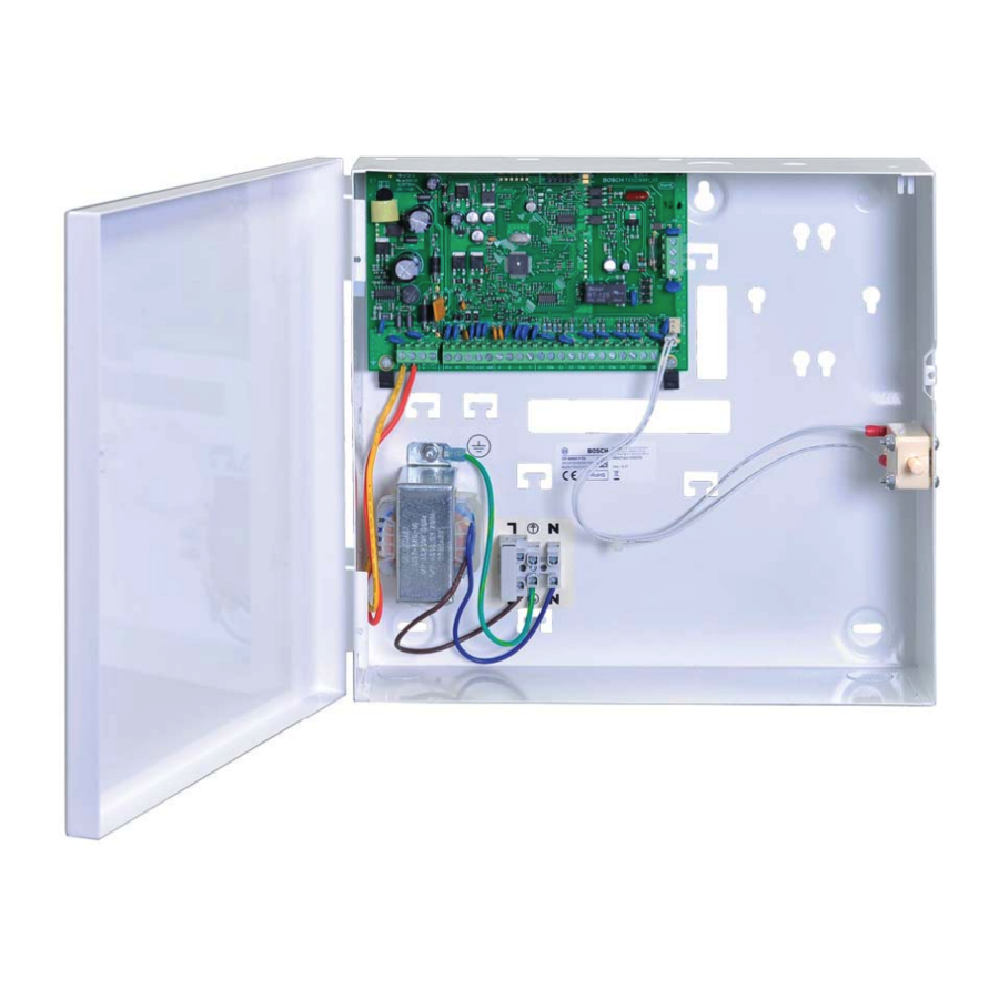
AMAX panel 2000 / AMAX panel 2000 EN Installation | en ICP-AMAX-P ICP-AMAX-P-EN 1 Tamper Switch 2 Zone Switch 3 EOL 2,2 k Keypad 1 Keypad 2 +12V Fuse 500 mA Figure 3.1 Wiring Diagram 3.1.1 Setting date and time Set the date and time after powering up the system, otherwise Date and Time Default to factory settings. -
Page 14: Amax Panel 2000 / Amax Panel 2000 En Zone Defaults
The installer code turns active only when it’s enabled by a user. You cannot enter installer’s programming mode if the system is armed, or during siren run time. You can program the AMAX panel 2000 / AMAX panel 2000 EN using any of these three devices: –... - Page 15 AMAX panel 2000 / AMAX panel 2000 EN Installation | en Enter the four-digit installer code (the factory default is 1234) + (958) and press [#] . Two beeps sound and the STAY and the AWAY indicators flash simultaneously to indicate that you have entered into installer’s programming mode.
-
Page 16: Programming With The Icp-Ezpk Programming Key
After saving information in the programming key, you can easily program other AMAX panel 2000 / AMAX panel 2000 EN with the same programming data. You can also use the programming key to back up existing information. -
Page 17: Prerequisites For An En-Conform Setup Of The System
AMAX panel 2000 / AMAX panel 2000 EN Installation | en If the LED on the control panel PCB does not fast flash, the factory default was unsuccessful. Prerequisites for an EN-conform Setup of the System – System must be mounted inside the monitored area on a stable surface. - Page 18 | Installation AMAX panel 2000 / AMAX panel 2000 EN Figure 3.4 Reassemble the Keypad (it’s now ready for use in you’re EN setup). F.01U.241.127 | V4 | 2011.12 Installation Manual Bosch Sicherheitssysteme GmbH...
-
Page 19: User Guide
AMAX panel 2000 / AMAX panel 2000 EN User Guide | en User Guide ICP-AMAX - LED8 - 8 Zone LED Keypad ICP-AMAX-LCD8 - 8 Zone LCD Keypad Quick keypad operation instructions Arming AWAY arm [code] + [#] / [#] (quick arming) - Page 20 | User Guide AMAX panel 2000 / AMAX panel 2000 EN Keypad Indicators LCD keypad LED keypad Status Definition indicator icons indicator lights Zone (1-8) Zone is triggered. Zone is normal. Fast flash (0.25 seconds lights on/ Zone was alarmed or is in alarm 1 2 3 ….
- Page 21 AMAX panel 2000 / AMAX panel 2000 EN User Guide | en Keypad sounds Sound indicator Definition One short beep A keypad button has been pressed. One single one- The requested operation is refused. Incorrect operation signal. second beep Two short beeps The system accepted the code. The system executed the requested function.
-
Page 22: Arming The System
| User Guide AMAX panel 2000 / AMAX panel 2000 EN Zone description Zone 1 ______________________________________________________ Zone 2 ______________________________________________________ Zone 3 ______________________________________________________ Zone 4 ______________________________________________________ Zone 5 ______________________________________________________ Zone 6 ______________________________________________________ Zone 7 ______________________________________________________ Zone 8 ______________________________________________________ Exit Time ___________________________________________________ sec... -
Page 23: Arming In Stay Mode
AMAX panel 2000 / AMAX panel 2000 EN User Guide | en The AWAY indicator flashes slow, and exit time starts. After exit time, the AWAY indicator is lit. Please contact your installer to enable/disable this function. Telephone remote arming The user dials the control panel number. -
Page 24: Forced Arming
| User Guide AMAX panel 2000 / AMAX panel 2000 EN 4.1.3 Forced arming Arming the system when a zone is not sealed is known as forced arming. If the AWAY indicator does not glow, and if a long beep sounds when you attempt to arm the system in AWAY Mode, then forced arming is not permitted. -
Page 25: Walk Test Mode
AMAX panel 2000 / AMAX panel 2000 EN User Guide | en RF Power Fault Warning Device Failure List Warning Device 1 Disconnected Warning Device 1 Short Warning Device 2 Disconnected Warning Device 2 Short Telephone Line Fail Date and Time Fail... -
Page 26: Reset The Control Panel
| User Guide AMAX panel 2000 / AMAX panel 2000 EN Example: If the events occurred in the following order: Sequence Event System armed in AWAY mode Alarm in Zone 3 Alarm in Zone 4 System disarmed The alarm memory is played back in this order:... -
Page 27: Bypassing Faults And Tamper Conditions (Except Zone Tampers)
AMAX panel 2000 / AMAX panel 2000 EN User Guide | en 4.7.2 Bypassing Faults and Tamper conditions (Except Zone Tampers) Bypassing Faults and Tamper conditions, one or more faults and tamper conditions are disabled for one arming cycle. After bypassing a Fault or Tamper condition, you can arm the system even when a Fault or Tamper condition exists. -
Page 28: Keypad Medical Alarm
| User Guide AMAX panel 2000 / AMAX panel 2000 EN 4.10.4 Keypad medical alarm If you simultaneously press and hold [7] and [9], a silent keypad emergency medical alarm will be transmitted. Please contact your installer to enable/disable the emergency medical alarm functionality. -
Page 29: Fault And Tamper Description
AMAX panel 2000 / AMAX panel 2000 EN Fault and Tamper Description | en Fault and Tamper Description Whenever a system fault or a tamper condition occurs, the FAULT or MAINS indicator flashes and the keypad beeps. To enter fault and tamper condition analysis mode to determine a system fault or tamper condition: Enter your Code and [2] and press [#] two beeps sound.The FAULT indicator remains lit... -
Page 30: Accessory Modules Fail
| Fault and Tamper Description AMAX panel 2000 / AMAX panel 2000 EN Zone Indicator Accessory Modules Fail ( Refer to 5.1 ) Keypad 1 fail (Refer to 5.1.1 ) Keypad 2 fail (Refer to 5.1.2 ) DX 3010 Fail (Refer to 5.1.3 ) B420/DX 4020 /-G Fail (Refer to 5.1.4 ) -
Page 31: Keypad 2 Fail
AMAX panel 2000 / AMAX panel 2000 EN Fault and Tamper Description | en Report the keypad fault to the configured destination programmed on location 140. Flash FAULT indicator on the other keypad in normal operation (refer to the detailed description in chapter keypad indicators). -
Page 32: Power Faults
| Fault and Tamper Description AMAX panel 2000 / AMAX panel 2000 EN Communication with DX4020/ITS-DX4020G is normal and fault is reset. Supervise: Report the DX4020/ITS-DX4020G fault to configured destination on location 140 when the fault is detected. Slow flash FAULT indicator (refer to the detailed description in chapter keypad indicators) When the fault is reset, send the restored report to the configured destinations. -
Page 33: Bosch Option Bus Power Supply Fail
Voltage is raised to 12.5V+-5% and fault is reset. Supervise: Monitor the voltage by MPU. Report the Bosch Option Bus Power Supply fault to the configured destination programmed on location 140. Slow flash FAULT indicator (refer to the detailed description in chapter keypad indicators) When the fault is reset, send the restored report to the configured destinations. -
Page 34: Warning Device 1 Short
| Fault and Tamper Description AMAX panel 2000 / AMAX panel 2000 EN When the fault is reset, send the restored report to the configured destinations. The FAULT indicator is turned off when there is no other system fault. -
Page 35: Date And Time Fail
AMAX panel 2000 / AMAX panel 2000 EN Fault and Tamper Description | en Slow flash FAULT indicator (refer to the detailed description in chapter keypad indicators) When the fault is reset, send the restored report to the configured destinations. The... -
Page 36: Communication Failure 4
| Fault and Tamper Description AMAX panel 2000 / AMAX panel 2000 EN The fault is reset when the first kissoff tone is received and fault is reset. Supervise: Report the fault to configured destination on location 140 when the fault is detected. -
Page 37: Keypad Lock Out
AMAX panel 2000 / AMAX panel 2000 EN Fault and Tamper Description | en The Tamper condition is reset when the Keypad is closed and Tamper condition is reset. Supervise: Report the Tamper condition to configured destination on Location 140 when the Tamper Condition is detected. -
Page 38: External Fault
| Fault and Tamper Description AMAX panel 2000 / AMAX panel 2000 EN Zone Tamper Zone Indication The zone indicator 6 lights to indicate Tamper conditions. Enter [6] to step to Zone Indicator list to identify the Tamper Zone. -
Page 39: System Functions
AMAX panel 2000 / AMAX panel 2000 EN System Functions | en System Functions User Install Function Description Code Code • • Duress alarm (Refer to 6.1 ) • • Siren test (Refer to 6.2 ) • • Fault and Tamper analysis (Refer to 6.3 ) •... -
Page 40: Siren Test
| System Functions AMAX panel 2000 / AMAX panel 2000 EN A Duress Alarm is useful only if your system reports to a monitoring station, because domestic reporting format cannot define the type of alarm that occurred. Siren Test This function allows code holders to test Sirens. -
Page 41: Event Memory Recall Mode
AMAX panel 2000 / AMAX panel 2000 EN System Functions | en If the operation is not carried out within 240 seconds after entering the walk test mode, the system will automatically exit from the setting. Event Memory Recall Mode This function allows you to play back the last 254 system events that occurred. -
Page 42: Initiate A Modem Call
| System Functions AMAX panel 2000 / AMAX panel 2000 EN NOTICE! You can only reset Alarms Faults or Tamper conditions, when the related contact or function is idle. Initiate a Modem Call Enter your Code + [7] and press # two beeps sound and the control panel dials the callback telephone number programmed in Location 154 –... -
Page 43: Bypass All Faults And Tamper Conditions (Except Zone Tamper)
AMAX panel 2000 / AMAX panel 2000 EN System Functions | en Enter your Code + [96] and press [#] . Two beeps sound and the STAY and AWAY indicators flash. Zone type for Zone 1 is shown. Refer to Section Zone Types, page 84 Press [#] to jump to Zone 2 Two beeps sound and the STAY and AWAY indicators flash. -
Page 44: Add/Delete User Codes
| System Functions AMAX panel 2000 / AMAX panel 2000 EN To set the date and time for the 25th of December 2010 at 10:30PM, enter: [1234] [955][#] break until time is shown [1 0 1 2 2 5 2 2 3 0][#] 6.16... -
Page 45: Change Domestic Phone Number
AMAX panel 2000 / AMAX panel 2000 EN System Functions | en To delete a Remote Radio User Code: Enter your Installer Code + 956 and press [#] . Two beeps sound and the STAY and AWAY indicators flash. Enter the number of the code (9 - 16) you want to change and press [#] . Two beeps sound and the corresponding zone indicator lights. -
Page 46: Command 960 - Exit From Installer's Programming Mode With Saving The Programming Data
| System Functions AMAX panel 2000 / AMAX panel 2000 EN 6.21 Command 960 – Exit from installer’s programming mode with saving the programming data This command exits from the installer’s programming mode with saving the programming data. You can exit from installer’s programming mode from any location. -
Page 47: Command 963 - Copy The Programming Key To The Control Panel
AMAX panel 2000 / AMAX panel 2000 EN System Functions | en 6.24 Command 963 – Copy the programming key to the control panel This command copies data from the programming key to the control panel. To copy the programming key to the control panel: Enter the installer code (the default is 1234 + 958) and press [#] to enter into installer’s... -
Page 48: System Informations 1
| System Informations 1 AMAX panel 2000 / AMAX panel 2000 EN System Informations 1 Zone Processing when arming When the system is armed, it will do the following process. Arm precondition: The system should be disarmed. Also the system should not be in programming mode and walk test mode. -
Page 49: Software
Record the event in history. Software You can program or control the AMAX panel 2000 / AMAX panel 2000 EN remotely using a PC and remote programming software. This software allows you to change your customer’s control panel without leaving your office. -
Page 50: Remotely Arm/Disarm System By Programming Softwares
7.6.1 Transmission Formats The AMAX panel 2000 / AMAX panel 2000 EN provides two kinds of transmission formats, Contact ID and CFSK format, for its dialing and communication features. Program the transmission format for Receiver 1, 2, 3 and 4 separately in Location 023, Location 053, Location 083 and Location 113(refer to Section 7.7.4 Receiver 1 - 4 Transmission Format,... -
Page 51: Cfsk Format
AMAX panel 2000 / AMAX panel 2000 EN System Informations 1 | en EEE = Event Code GG = Group Number (always 0) CCC = Zone/ Contact ID, 000 is for no zone/ID message S = Checksum digit Note: Any 0 values must be sent as an 0x0A. -
Page 52: Telephone Number For Receiver 1 - 4/Ip Address And Port
| System Informations 1 AMAX panel 2000 / AMAX panel 2000 EN Digit Required Number to Program Digit Required Number to Program 4 sec pause Terminal Table 7.1 Dialing Digits To program the IP Address and port: Use no punctuation in IP address. If any unit of IP address is less than 3 digits, use 0 to fulfill the data in the higher bits. -
Page 53: Report Transmission Sequence
If Contact ID or CFSK format is selected, the information is transmitted by telephone line; if Bosch Network is selected, then it is connected with B420/DX4020 or ITS-DX4020G GPRS. Transmission format is defaulted as Contact ID. -
Page 54: Receiver 1 - 4 Subscriber Id Number
AMAX panel 2000 / AMAX panel 2000 EN User Codes (Refer to Section 10.6.2 User Codes, page 87.) The AMAX panel 2000/AMAX panel 2000 EN Control Panel can have up to sixteen programmable User Codes (1 - 16) to operate the system. -
Page 55: User Codes
AMAX panel 2000 / AMAX panel 2000 EN System Informations 1 | en 7.8.3 User Codes The purpose of User Codes is to arm and disarm the system and perform system functions. Refer to Section 6 System Functions, page 39. User Codes 1 to 8 can be one to four digits long. -
Page 56: System Informations 2
8.1.1 Zone Inputs On-board Inputs: There are 8 onboard hard-wired inputs for AMAX panel 2000 / AMAX panel 2000 EN. An additional input is provided for enclosure tamper but does not subtract from the 8 onboard totals. On-board Zone Response Time: Each on-board zone response time is: Zone Status trigger time >= 400ms, must response... -
Page 57: Zone Programming
AMAX panel 2000 / AMAX panel 2000 EN System Informations 2 | en 1650 2200 2750 normal 2970 4400 4950 trigerred Using one 2.2K resistor as EOL of the tamper zone, which works together with the zone EOL 2.2K. Refer to the drawing: Figure 8.3 Dual EOL... - Page 58 | System Informations 2 AMAX panel 2000 / AMAX panel 2000 EN AWAY Arm: Zone normal - no Alarm / no report Zone triggered - Alarm / report (Zone triggered during exit time no Alarm / no report) (Zone triggered during entry time Alarm / report is delayed for 30sec or entry time is...
- Page 59 AMAX panel 2000 / AMAX panel 2000 EN System Informations 2 | en Disarm: same as the Instant Zone disarm status AWAY Arm: same as the Delay Zone AWAY Arm status STAY Arm: This Zone will be Ignored and performed as disarm.
- Page 60 | System Informations 2 AMAX panel 2000 / AMAX panel 2000 EN Disarm: Zone normal - no Alarm / no report Zone triggered - Alarm / report AWAY Arm: Zone normal - no Alarm / no report Zone triggered - Alarm / report...
- Page 61 AMAX panel 2000 / AMAX panel 2000 EN System Informations 2 | en STAY Arm: Same as AWAY Arm performance. This zone is mainly for prevention of arming (to ensure exit/entry door is locked before arming the system and no alarm occurs when entering the premise through the entry/...
-
Page 62: Zone Bypass
1. Lockout is activated per arming cycle (that is, a zone programmed for Lockout can activate sirens/report only 1 time). After the system disarm/ arm again, the lockout counting will be reset.The AMAX panel 2000 / AMAX panel 2000 EN Control Panel performs lockout: When the zone is triggered an alarm is created and the siren is activated in an alarm (output for siren run) time. -
Page 63: Zone Tamper
AMAX panel 2000 / AMAX panel 2000 EN System Informations 2 | en 3. 3 Times Alarm Lockout Same as 1 time alarm lockout, but the lock out time is 3. 4. 4- 6 Times Alarm Lockout Same as 3 times alarm lockout, but the lock out time is 6. -
Page 64: System Option Programming Definition
| System Informations 2 AMAX panel 2000 / AMAX panel 2000 EN 8.2.1 System Option Programming Definition If the system programming data is not correct, the keypad beeps to indicate wrong operation but the data is kept as the same. -
Page 65: System Report And Memory Definition
AMAX panel 2000 / AMAX panel 2000 EN System Informations 2 | en 8.2.2 System Report and Memory Definition System Report and Memory List Event CID Point CFSK Report Type Event Event Event Type Memory Code ALL EN Alarm Burglar... - Page 66 | System Informations 2 AMAX panel 2000 / AMAX panel 2000 EN Option Bus Power fail 300 1 System status • Option Bus Power 300 3 System status • restore RF Power fail 300 1 System status • RF Power restore...
- Page 67 AMAX panel 2000 / AMAX panel 2000 EN System Informations 2 | en User code for arming/disarming report Arming/Disarming Method AWAY/STAY arming Disarming Key-switch zone User 17 (Only AWAY arming) User 17 Single button arming User 18 Remote telephone arming...
-
Page 68: Auto Test Report
| System Informations 2 AMAX panel 2000 / AMAX panel 2000 EN Keypad – Medical Report A Medical Report is sent to the base station destination when a user presses [7] and [9] at the same time.Restore Reports are not sent for this event. -
Page 69: System Event Memory Recall
Press [#] to exit from the Event Play Back Mode at anytime. Output Process The AMAX panel 2000 / AMAX panel 2000 EN Control Panel has three outputs on the main board and 8 outputs on the DX3010 relay module. The Output 1 is used as Siren alarm. During the alarm duration, the system can reset the alarm by command “reset”... - Page 70 | System Informations 2 AMAX panel 2000 / AMAX panel 2000 EN The output is reset: When the system is disarmed When the output programmed duration is up. If this duration is programmed as 000, the output will continue till the system disarmed.
- Page 71 AMAX panel 2000 / AMAX panel 2000 EN System Informations 2 | en Only after a Dynamic Battery Test report that the backup battery voltage is normal and fault is reset. When the output programmed duration is up. If this duration is programmed as 000, the output will continue till the AC MAINS power is restored.
-
Page 72: Output Type
| System Informations 2 AMAX panel 2000 / AMAX panel 2000 EN When a new alarm occurred, the alarm will reset the alarm time. 15 – Reset This output operates when a reset is performed in the system. 8.4.2... -
Page 73: Exit Time
8.6.4 A-Link Plus Software This A-Link Plus software package is designed to program the AMAX panel 2000 / AMAX panel 2000 EN Control Panel by remote connect methods. This software can access all options and features and in addition to maintaining history and service reports. Program options to use this feature in Location 153. -
Page 74: B420/Dx4020/Its-Dx4020G Gsm Gprs Communication Module
8.6.6 B420/DX4020/ITS-DX4020G GSM GPRS Communication Module The AMAX panel 2000 / AMAX panel 2000 EN Control Panel supports one B420 or one DX4020 network communication module or ITS-DX4020G GSM/GPRS communication module. Only one can be selected to connect in one system to send reports thought the network. -
Page 75: Technical Data
AMAX panel 2000 / AMAX panel 2000 EN Technical Data | en Technical Data Specification Panel Enclosure : Dimensions (HxWxD): – 260mm x 280mm x 83,5mm Weight: – 1950g Environmental Considerations : Relative Humidity: – 10%-95% Operating Temperature: – -10°C - +55°C... - Page 76 | Technical Data AMAX panel 2000 / AMAX panel 2000 EN Aux (+12V/GND) Output: – Nominal Output Voltage under AC line input: 13,5 VDC +3% / -5% – Output Voltage Range under AC line input: 12,82 VDC to 13,9 VDC –...
-
Page 77: Interface Description
AMAX panel 2000 / AMAX panel 2000 EN Technical Data | en Interface Description 9.2.1 Terminals Internal Description Terminal Description These two terminals are the plug-on type and are the terminal points for the 18 VAC transformer. To ensure correct operation, the voltage of the transformer must be 18 VAC to 22VAC at 1.3 A (minimum) -
Page 78: Programming Sheets
| Programming sheets AMAX panel 2000 / AMAX panel 2000 EN Programming sheets 10.1 Receiver Programming 10.1.1 Receiver Parameters Report Options Location Default Telephone Number/IP Address and Port for Receiver 1 000-016 Subscriber ID Number for Receiver 1 017-022... -
Page 79: Domestic Programming
AMAX panel 2000 / AMAX panel 2000 EN Programming sheets | en Example: For IP Address for receiver 128.73.168.7, communication port 7700, program as: 128 073 168 007 07700 NOTICE! Programming option anti-replay, acknowledge wait time and pulse interval time are only used in Bosch network format. -
Page 80: Test Report Time Interval Setting
| Programming sheets AMAX panel 2000 / AMAX panel 2000 EN Zone Status Reporting Options Report to Receiver 1,2,3,4 Report to destination 1 (2,3,4 backup) Report to destination 1 (2 backup) and destination 3 (4 backup) NOTICE! The system sends no report when programmed to report to the receiver as Option 0. -
Page 81: Keypad Lockout
AMAX panel 2000 / AMAX panel 2000 EN Programming sheets | en 10.3.6 Keypad Lockout Location 179 Location Default 1 - 15= attempt times 0=no lockout EN=10 If an invalid code attempts more times than programmed, the keypad is locked out for 3 minutes. -
Page 82: Ac Fault Detect Time
| Programming sheets AMAX panel 2000 / AMAX panel 2000 EN 10.3.16 AC Fault Detect time Location 189-190 Location Default 0-60 Minutes 189-190 10.3.17 Battery Detect time Location 191 Location Default 1-15 min EN=15 10.3.18 Event Record Count Per Set/Unset Period... - Page 83 AMAX panel 2000 / AMAX panel 2000 EN Programming sheets | en Reserved 228-229 Zone #03 Zone Type (Refer to zone type option) Zone Bypass (Disable=0, Enable=1) Forced Arming (Disable=0, Enable=1) EN=0 Silent Alarm (Enable=1, Disable=0) EN=0 Zone alarm lock out time (disable=0, 1 times=1, 3 times=2, 6...
- Page 84 | Programming sheets AMAX panel 2000 / AMAX panel 2000 EN Silent Alarm (Enable=1, Disable=0) EN=0 Zone alarm lock out time (disable=0, 1 times=1, 3 times=2, 6 times=3, alarm duration=4) Support Detector Tamper (Disable=0, Enable=1) Zone alarm report (Refer to zone report option)
-
Page 85: Output Programming
AMAX panel 2000 / AMAX panel 2000 EN Programming sheets | en Zone Type Description 24-Hour Tamper Fire External Fault Bolt Contact Key Switch Toggle Key Switch on/off 10.5 Output Programming 10.5.1 Keypad Buzzer Location 370 Location Default Keypad beeps when siren on 1=Disable, 1=Enable 10.5.2... - Page 86 | Programming sheets AMAX panel 2000 / AMAX panel 2000 EN Polarity Mode (0=Steady, 1=Pulse) Output Duration (001-999sec/000=on) 387-389 Relay Output 2 Event Type (Refer to output events option) Polarity Mode (0=Steady, 1=Pulse) Output Duration (001-999sec/000=on) 392-394 Relay Output 3...
-
Page 87: Installer/User Code Programming
AMAX panel 2000 / AMAX panel 2000 EN Programming sheets | en Event Type Description No output activate for the events System Disarmed System Armed System Alarm Entry/Exit Delay Warning Telephone Line Fail AC Lost Battery Low RF Power Fault... - Page 88 | Programming sheets AMAX panel 2000 / AMAX panel 2000 EN User #07 460-464 User #08 465-469 RF User #09 470-474 EN=15 RF User #10 475-479 EN=15 RF User #11 480-484 EN=15 RF User #12 485-489 EN=15 RF User #13...
-
Page 89: Troubleshooting
AMAX panel 2000 / AMAX panel 2000 EN Troubleshooting | en Troubleshooting Trouble Causes & Measures No immediate response – To work normally, operate the system one minute after from zone testing right powered up. after powered up. No indication on keypad –... - Page 90 | Troubleshooting AMAX panel 2000 / AMAX panel 2000 EN Trouble Causes & Measures Battery fault still – System test the battery each time arming or every time set indicates after replaced in location 191. Only after testing the battery fault can be with new battery.
- Page 92 Bosch Sicherheitssysteme GmbH Robert-Bosch-Ring 5 85630 Grasbrunn Germany www.boschsecurity.com © Bosch Sicherheitssysteme GmbH, 2011...