Kenwood NX-5000 Series Common Function Reference
Hide thumbs
Also See for NX-5000 Series:
- User manual ,
- Manual (264 pages) ,
- Function reference (190 pages)
Table of Contents
Quick Links
See also:
User Manual
Table of Contents

Related Manuals for Kenwood NX-5000 Series


Summary of Contents for Kenwood NX-5000 Series
- Page 1 NX-5000 series Common Function Reference (Common FUNC) Version: 2.20 Last Updated: June 30, 2017 Language: English Type: K, F © 2017...
- Page 2 CONTENTS CONTENTS CONTENTS About This Manual viii GETTING STARTED How to Read the In-depth Manual Connecting the Transceiver to a PC About Notations Connecting the Transceiver to a PC by About the Notation of the Supported Bluetooth Models Writing the Configuration Data to the About Examples of the Transceiver Transceiver Display...
-
Page 3: Table Of Contents
CONTENTS Transmitting/ Receiving INDICATION AND DISPLAY Viewing the Receive History (Stack) Busy LED Configuring the Display Order of Data in Transmit LED Stack Mode (Stack Order) Selective Call Alert LED Enabling the Storage of Redundant Data (Repeated Calls Stack) Optional Signaling LED Displaying the Caller ID when Displaying Lighting the Backlight (Backlight) - Page 4 CONTENTS Tones that Sound When the Transceiver BATTERY Receives a Call Displaying the Remaining Battery Power Configuring the Alert Tone (Alert Tone Level (Battery Indicator) Pattern) Warning that the Battery Voltage Is Low Tones that Sound When the (Battery Warning) Communication Starts/ Ends Warning the Battery Power of the Vehicle Using Sound to Notify the Timing to Start...
- Page 5 CONTENTS 10.7 Switching the Speaker to Emit Audio 10 BLUETOOTH COMMUNICATION (Bluetooth Speaker) 10.1 Toggling Bluetooth On/ Off Determining the Speaker to Emit by Linking with the Microphone Hook (Off- 10.2 Finding a Bluetooth-compatible Device hook Speaker Revert) (Bluetooth Find Device) 10.8 Resetting the GPS/ Bluetooth Device About the Displayed Contents of a...
- Page 6 CONTENTS 12 FUNCTIONS LINKED TO A 14 ADJUSTING THE TIME ON THE VEHICLE TRANSCEIVER 12.1 Turning the Transceiver ON or OFF 14.1 Displaying the Current Time According to the State of the Ignition Sense 14.2 Adjusting the Time Port (Ignition Sense) Usage of the Ignition Sense Port 15 MODE The Amount of Time Until the...
- Page 7 CONTENTS 16.12 Microphone-hook 16 MULTI RF DECK/ MULTI CONTROL HEAD 16.13 GPS 16.14 Scan 16.1 Description 16.15 Communications in an Emergency 16.2 Structures of Multi RF Deck/ Multi Control (Emergency) Head 16.16 Bluetooth Communication 16.3 Building a Multi RF Deck System Bluetooth On/Off 16.4 Configuring the Initial Configuration...
- Page 8 CONTENTS 17 STRUCTURING A MULTI RF DECK/ 18 VOX MULTI CONTROL HEAD 18.1 Configuring the Input Sensitivity of the Microphone (VOX Gain Level) 17.1 Initial Configuration for Multi RF Deck/ Multi Control Head 18.2 Retaining Transmitting State after VOX Transmission (VOX Delay Time) Attaching KRK-15BM to the RF Deck 18.3...
- Page 9 About This Manual About This Manual This In-depth manual describes the functions of the transceiver (NX-5200/ NX-5300/ NX-5400/ NX-5700/ NX-5800/ NX-5900) used in common in each of an analog, P25, NXDN, and DMR systems. This document is created for the product having the following design specifications. Item Specifications How to Verify...
-
Page 10: Common Func (K, F)/Ver
About This Manual DMR system Function Name Radio Feature License DMR Conventional KWD-5300CV Common Function Name Radio Feature License 4000 Channel KWD-5000CH Front Panel Programming KWD-5001FP microSD KWD-5002SD Bluetooth Serial Port Profile KWD-5003BT KWD-5004MR Multi RF Deck Remote Control KWD-5007RC Implemented before the factory shipment. - Page 11 About Notations About Notations The following notations are used in this manual. The characters in [ ] indicate the name of the operating portion of the transceiver and the key of the PC. “ ” (Double Quotation Mark) The characters in “ ” indicate the name of the functions, buttons, and menus shown on the KPG-D1/ KPG-D1N or the display of the transceiver.
- Page 12 Abbreviations Used in This Document Abbreviations Used in This Document The following abbreviations are used in this in-depth manual. Refer to the abbreviation table below. Abbreviation Full Spelling or Meaning Acknowledgment Active Noise Reduction Advanced Encryption Standard AMBE+2 Advanced Multi-Band Excitation ARC4 Alleged RC4 Auxiliary...
- Page 13 Bluetooth SIG, Inc., and any use of such marks by JVC KENWOOD Corporation is under license. All other trademarks and trade names are the trademarks and trade names of their respective owners.
- Page 14 About the Programming Software About the Programming Software Various functions and parameters of the transceiver can be configured by using the KPG-D1/ D1N software. Various functions can be enabled by connecting the transceiver to a PC by use of the KPG-36U/ KPG-36X (Portable) or KPG-46U/ KPG-46X (Mobile) programming cable and writing the data configured using KPG-D1/ D1N to the transceiver.
- Page 15 About the Programming Software About System Type For KPG-D1/ D1N, a System Type (Analog Conventional, P25 Conventional, NXDN Conventional, P25 Trunking, NXDN Trunking, LTR Trunking, P25 Voting with NAC, NXDN Site Roaming or NXDN Site Roaming with RAN, or DMR Conventional, DMR Site Roaming) needs to be selected in System Information of KPG-D1/ D1N in order to configure the system data or Zone-channel data of each communication system.
- Page 16 About Options to Use the Functions Described in This Document About Options to Use the Functions Described in This Document To use the functions described in this document, the following KENWOOD optional accessories need to be prepared on your own as necessary. Portable/ Mobile...
- Page 17 About the Built-in GPS Receiver Unit About the Built-in GPS Receiver Unit The GPS receiver is built-in for NX-5200/ NX-5300/ NX-5400/ NX-5700/ NX-5800/ NX-5900. Read the following warnings before using the built-in GPS receiver unit of NX-5200/ NX-5300/ NX-5400/ NX-5700/ NX-5800/ NX-5900. On the use of the GPS With frequency interference in the GPS receive frequency range to the transceiver or another transceiver, the GPS receiver may not position normally.
- Page 18 How to Search for Information INDEX Clicking a function name, a title or a page number in the Index pages allows a jump to the corresponding page. Blue Characters in the Main Text Clicking a portion with blue characters in the main context allows a jump to the corresponding page. Blue Characters at the Bottom of Each Page Clicking a portion with blue characters located at the bottom of each page allows a jump to the first page of the contents or index.
- Page 19 Outline of This Transceiver Outline of This Transceiver NX-5200/ NX-5300/ NX-5400/ NX-5700/ NX-5800/ NX-5900 is the VHF/ UHF or 700 MHz/ 800 MHz transceiver for the use of professionals. The transceiver is equipped with the digital communications system (conventional and trunking) which complies with the NXDN, P25, and DMR common air interface specifications, as well as the existing analog FM mode.
- Page 20 Outline of This Transceiver P25 DIGITAL MODES GENERAL P25 Digital Air Interface AMBE+2 VOCODER 12.5 kHz Channel Spacing Individual Call Group Call Emergency Call All Group Call Radio Inhibit / Uninhibit Remote Monitor Ignition On/ Off GPS Reporting (Mobile only) Single Scan, List Scan AES &...
- Page 21 Outline of This Transceiver CONVENTIONAL MODE TRUNKING MODE 63 Radio Access Numbers (RAN) Individual Call Individual Call & Group Call Group Call & Broadcast Call Mixed FM/ Digital Operation Telephone Call Site Roaming Transmission Trunked Mode 2-tone Message Trunked Mode Multi-Zone Scan 4 Priority Monitor IDs Remote Group Add...
- Page 22 Outline of This Transceiver ANALOG MODES GENERAL 12.5 kHz (Narrow)/ 20.0 kHz (Wide 4k) (NX-5400/ NX-5900 only)/ 25.0 kHz (Wide) Channel Spacing Conventional & LTR Systems FleetSync/ FleetSync II, MDC-1200, DTMF QT/ DQT/ 2-tone Single Scan, List Scan Priority Scan Multi-Zone Scan Voice Inversion Scrambler (16 Codes) FleetSync...
- Page 23 Revision History Revision History Date Description Added NX-5900 (700/ 800 MHz model) as a supported model. Added the information of KCH-20R (Featured Panel) as a supported Control Head. Added KPG-36X and KPG-46X as supported programming cables. Changed the description in “About this Manual” as follows: Changed the version information Changed the Left Up key to the [+] key Added Radio Feature License...
- Page 24 Revision History Date Description 28) Added the items of Analog and LTR Trunking to Table 5-1. 29) Added the description of “Full Color White” in “5.6 Changing the Color Scheme of the Transceiver Display (Color Scheme)”. 30) Added a supported icon to Table 5-2. 31) Added the description of “FleetSync ID”...
- Page 25 Revision History Date Description 69) Added the note in “Flow Control of the Communication Port (Flow Control)”. 70) Added the keys of KCH-20R (Featured Panel) to the table in “Key Operations for Each Mode”. 2015.11.30 71) Changed the version number from 1.00 to 1.60. Added the DMR and 5-tone information in “About this Manual”...
- Page 26 Revision History Date Description 37) Added “16.18 Relaying the Received Signal (Mobile Relay Station)”. 38) Added “17.1 Initial Configuration for Multi RF Deck/ Multi Control Head”. 39) Added “17.13 About the Pin Arrangement for KCT-72 When an External Device is Connected”. 40) Added the following items to Table 19-1: Call Interruption, Digit 10x Down, Digit 10x Up, Digit 1x Down, Digit 1x Up, Mobile Relay Station, OVCM, Receive Entry, Remote Control, RF Deck Down, RF Deck Up, System Down, System Down (Continuous), System Lock, System Select,...
- Page 27 Revision History Date Description 23) Added the description of KCH-21R (Handheld Control Head) to the following items: 16.1 Description 16.5 Basic Operations 16.16 Bluetooth Communication 17.9 Changing the Display Positions of a Channel Name and an Icon When Multi RF Deck View Is On “Multi RF Deck View”...
- Page 28 Revision History Date Description 23) Added “External Speaker” to Table 11-3. 24) Added “External Speaker” in “Available Functions for AUX Input Ports”. 25) Added the description about Conventional Channel (DMR) in “TOR” to Table 11-8. 26) Added the note to “AUX Output Status Message 1 to AUX Output Status Message 3” in Table 11-8. 27) Added “Digital Mode”...
- Page 29 CONTENTS BY PURPOSE Configuring Various Functions for the Assigning Functions to the Keys on the Basic Transceiver Transceiver Configurations for Using the Frequencies and signaling for transmission and Various functions can be assigned to the PF Transceiver reception, channel data, including the transmit keys on the transceiver.
- Page 30 CONTENTS BY PURPOSE Lighting the LED While Transmitting and Displaying the Transceiver Received Signal Indication Receiving Strength and Display The transceiver can light or flash the LED while The received signal strength of the transceiver the transceiver is transmitting or receiving. can be displayed on the transceiver display.
- Page 31 CONTENTS BY PURPOSE Turning the Transceiver ON or OFF by Turning the Headlights On of the Vehicle or Functions of Linking with a Vehicle Ignition Making the Horn Sound When the Transceivers Transceiver Receives a Call for Vehicles For Mobile, the transceiver can automatically be turned ON or OFF by linking with the status of For Mobile, by using the horn alert function, the the port linked with the vehicle ignition by using...
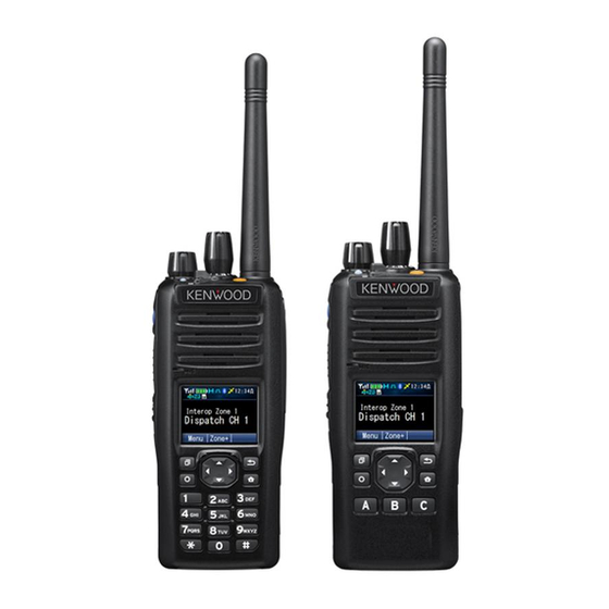
- Page 32 1 FUNCTIONS AND PANEL LAYOUT FUNCTIONS AND PANEL LAYOUT NX-5200/ NX-5300/ NX-5400 Full Key Model Standard Key Model Figure 1-1 NX-5200/ NX-5300/ NX-5400 Front View Selector PTT Switch The preassigned function will be activated or will be Pressing the PTT switch allows transmitting. changed to the active state.
- Page 33 1 FUNCTIONS AND PANEL LAYOUT 1.1 NX-5200/ NX-5300/ NX-5400 [O] (Back) Key [T] (Home) Key The preassigned function will be activated or will be The preassigned function will be activated or will be changed to the active state. In this manual, the [O] changed to the active state.
- Page 34 1 FUNCTIONS AND PANEL LAYOUT 1.2 NX-5700/ NX-5800/ NX-5900 NX-5700/ NX-5800/ NX-5900 KCH-19 (Basic Panel) Figure 1-2 NX-5700/ NX-5800/ NX-5900 Front View (KCH-19 (Basic Panel)) [P] (Power) Switch [Q] (Menu) Key The transceiver is turned ON when this switch is pressed The preassigned function will be activated or will be and the transceiver is turned OFF when this switch is changed to the active state.
- Page 35 1 FUNCTIONS AND PANEL LAYOUT 1.2 NX-5700/ NX-5800/ NX-5900 KCH-20R (Featured Panel) Figure 1-3 NX-5700/ NX-5800 Front View (KCH-20R (Featured Panel)) Transmit LED [P] (Power) Switch This LED lights when the transceiver transmits a signal. The transceiver is turned ON when this switch is pressed and the transceiver is turned OFF when this switch is Busy/ Status LED pressed again.
- Page 36 1 FUNCTIONS AND PANEL LAYOUT 1.2 NX-5700/ NX-5800/ NX-5900 Selector [W] (Function) Key The preassigned function will be activated or will be The preassigned function will be activated or will be changed to the active state. It is normally used to change changed to the active state.
- Page 37 1 FUNCTIONS AND PANEL LAYOUT 1.2 NX-5700/ NX-5800/ NX-5900 KCH-21R (Handheld Control Head) KCH-21R is the Handheld Control Head that can be used by connecting to Mobile. By using KCH-21R, the transceiver can be operated in hand as Portable. Figure 1-4 KCH-21R (Handheld Control Head) Front View [A] Key [G]/ [H] Key The preassigned function will be activated or will be...
- Page 38 1 FUNCTIONS AND PANEL LAYOUT 1.2 NX-5700/ NX-5800/ NX-5900 Keypad [W] (Function) Key The transceiver can be operated by pressing a key. The preassigned function will be activated or will be changed to the active state. In this manual, the [W] (Function) key is described as the Function ([W]) key.
- Page 39 1 FUNCTIONS AND PANEL LAYOUT 1.2 NX-5700/ NX-5800/ NX-5900 External Microphone (KMC-25) Figure 1-6 KMC-25 PTT Switch PF 2 Key Pressing the PTT switch allows transmitting. The preassigned function will be activated or will be changed to the active state. PF 1 Key The preassigned function will be activated or will be changed to the active state.
- Page 40 1 FUNCTIONS AND PANEL LAYOUT 1.3 About LCD About LCD The LCD of the transceiver is as follows. The contents that appear on the LCD varies depending on the transceiver’s status. Portable Basic Frame This frame is used to display the name, such as the channel name. Various icons indicating the transceiver’s status appear in the icon display area.
- Page 41 1 FUNCTIONS AND PANEL LAYOUT 1.3 About LCD Category Icon Frame This frame is used to display the Menu Category in Icon Mode. Displays vary depending on the configuration in Menu Icon Size. The following screens are display examples if Menu Icon Size is configured “Large”. (Refer to Using Menu Mode.) Icon...
- Page 42 1 FUNCTIONS AND PANEL LAYOUT 1.3 About LCD Function Mode Frame 1 This frame is used to display the Function Mode, such as Individual Call Mode and Status Mode. The number, such as the list number or channel number, appears at the right end of the title line. Icon Clock 12 : 34...
- Page 43 1 FUNCTIONS AND PANEL LAYOUT 1.3 About LCD Mobile (KCH-20R (Featured Panel)) Basic Frame This frame is used to display the name, such as the channel name. Various icons indicating the transceiver’s status appear in the icon display area. Icon Clock 12 : 34 Sub Display (6 characters)
- Page 44 1 FUNCTIONS AND PANEL LAYOUT 1.3 About LCD Message Frame This frame is used to display the message, such as the Short Message. Icon Clock 12 : 34 Title (32 characters) XXXXXXXXXXXXXXXXXXXXXXXXXXX XXXXXXXXXXXXXXXXXXXXXXXXXXXXXX Line 1 (32 characters) XXXXXXXXXXXXXXXXXXXXXXXXXXXXXX Line 2 (32 characters) XXXXXXXXXXXXXXXXXXXXXXXXXXXXXX Line 3 (32 characters) XXXXXXXXXXXXXXXXXXXXXXXXXXXXXX...
- Page 45 1 FUNCTIONS AND PANEL LAYOUT 1.3 About LCD Mobile (KCH-21R (Handheld Control Head)) Basic Frame This frame is used to display the name, such as the channel name. Various icons indicating the transceiver’s status appear in the icon display area. Icon Clock 12 : 34...
- Page 46 1 FUNCTIONS AND PANEL LAYOUT 1.3 About LCD Category Icon Frame This frame is used to display the Menu Category in Icon Mode. Icon Clock 12 : 34 Category Icon XXXXX Category Name (14 characters) List Number X XX X XX XX X Key Guide (6 characters) Popup Display...
- Page 47 1 FUNCTIONS AND PANEL LAYOUT 1.3 About LCD Icons Various icons indicating the transceiver’s status appear in the icon display area when a channel name is displayed. Refer “The Icons on the LCD” for details of each icon. Portable 12 : 34 XXXXX XXXXX XXXXX...
- Page 48 1 FUNCTIONS AND PANEL LAYOUT 1.3 About LCD Key Guide The key guide is displayed at the bottom of the LCD. For Portable, the key guide displays the functions that function when the Menu ([Q]), [G] or Back ([O]) key is pressed. For Mobile, the key guide displays the functions that function when the Menu ([Q]), Back ([O]) or [E], [F] key is pressed.
- Page 49 1 FUNCTIONS AND PANEL LAYOUT 1.3 About LCD Function Mode Functions that can be used in each mode appear while the transceiver is in Function Mode, such as Selcall Mode, Status Mode and Stack Mode. However, the key guide for the Up key does not appear if the function which is used to select the list or code is assigned to the [G] or [H] key.
- Page 50 1 FUNCTIONS AND PANEL LAYOUT 1.3 About LCD The following are key guides that appear while the transceiver is in Function Mode. (Refer to Function Mode.) Table 1-1 Key Guide (Function Mode) Key Guide Operation Determines the data of the entered characters, code, or list. Select Determines the data of the selected characters, code, or list.
- Page 51 2 GETTING STARTED GETTING STARTED When the transceiver is turned ON after the power source is attached to the transceiver, the transceiver starts up. To make the transceiver ready for use, the configuration data needs to be created using KPG-D1/ D1N and written to the transceiver. Figure 2-1 KPG-D1/ D1N Main Window By using KPG-D1/ D1N, the zone and channel data needs to be configured and then the parameters for various functions can be configured.
- Page 52 2 GETTING STARTED 2.1 Connecting the Transceiver to a PC Connecting the Transceiver to a PC To write the configuration data to or read the configuration data from the transceiver via serial communications by using a programming cable, “Programming Cable” needs to be selected from Communication Method of COM port. Also, the transceiver and a PC with KPG-D1/ D1N installed need to be connected by using the programming cable.
- Page 53 2 GETTING STARTED 2.2 Connecting the Transceiver to a PC by Bluetooth Connecting the Transceiver to a PC by Bluetooth To write the configuration data to the transceiver or to read the configuration data from the transceiver by using Bluetooth communication, “Bluetooth SPP”...
- Page 54 2 GETTING STARTED 2.3 Writing the Configuration Data to the Transceiver Writing configuration data to multiple transceivers using Bluetooth communication To write configuration data to multiple transceivers by using Bluetooth communication, click the “Multi Write (Bluetooth)” button. A Bluetooth-compatible device (the transceiver) is detected in Write Data to Multiple Transceiver (Bluetooth), and the configuration data can be written to the transceiver by Bluetooth communication.
- Page 55 2 GETTING STARTED 2.5 Embedding a Message in the Transceiver (Embedded Message) Embedding a Message in the Transceiver (Embedded Message) The message can be written to the transceiver as part of the configuration data by using KPG-D1/ D1N. Embedded Message Embedded Message can be used to store a maximum of 64 characters in the transceiver.
- Page 56 2 GETTING STARTED 2.6 Writing Configuration Data Using Wireless Communication (OTAP) Writing Configuration Data Using Wireless Communication (OTAP) OTAP (Over-The-Air Programming) is the function to write configuration data to the transceiver using wireless communications. This function enables configuration data for the transceiver to be updated by remotely controlling from the base station.
- Page 57 3 BASIC OPERATIONS BASIC OPERATIONS Turning the Transceiver ON/ OFF Turning the Transceiver ON For Portable, rotating the Power switch clockwise causes the transceiver to be turned ON. For Mobile, pressing the Power switch causes the transceiver to be turned ON. Also, the transceiver can be turned ON by linking to the status of the Ignition Sense port of a vehicle.
- Page 58 3 BASIC OPERATIONS 3.1 Turning the Transceiver ON/ OFF If the data is written to the transceiver and the transceiver’s password is configured Turn the Transceiver ON. A Power-on Tone A (1 beep) sounds from the transceiver, and then an animated logo appears for 500 ms.
- Page 59 3 BASIC OPERATIONS 3.1 Turning the Transceiver ON/ OFF Note If the firmware is not written to the transceiver correctly, the transceiver will enter Firmware Programming Mode. In this case, write the firmware to the transceiver again. “UNPROGRAM” appears on the main display if no data is written to the transceiver. In this case, data needs to be written to the transceiver by using KPG-D1/ D1N.
- Page 60 3 BASIC OPERATIONS 3.2 Adjusting the Volume Level Adjusting the Volume Level Portable Rotating the Volume control clockwise increases the volume level from the speaker, and rotating the Volume control counterclockwise decreases the volume level from the speaker. Mobile Pressing the Volume Up key increases the volume level in steps of 1. Pressing the Volume Down key decreases the volume level in steps of 1.
- Page 61 3 BASIC OPERATIONS 3.3 Using Function Keys Mode Reset Timer Mode Reset Timer is the timer for canceling the standby status of further key entry in Function Mode, and for canceling the function activation status of 2nd Function. By using this function, Function Mode does not need to be disabled manually. The function also helps by canceling the Function Mode automatically so as not to remain in Function Mode for too long a time.
- Page 62 3 BASIC OPERATIONS 3.3 Using Function Keys Free-dial Entry Mode GPS Mode GPS/Bluetooth Reset Mode GPS Position Display Mode Group Call Mode Group ID Entry Mode High Transmit Power Mode Horn Alert Mode Individual Call Mode Intercom Mode IP Address Mode Key Delete Mode Keyset Select Mode Language Mode...
- Page 63 3 BASIC OPERATIONS 3.3 Using Function Keys Scan Mode Scan Delete/Add Mode Scan Normal Mode Scan Program Mode Scrambler/Encryption Mode Scrambler/Encryption Code Mode SD Card Direct Access Mode Selcall Mode Site Lock Mode Site Select Mode Speaker 1-2 Mute Mode Speaker Type Mode Squelch Level Mode Squelch Off Mode...
- Page 64 3 BASIC OPERATIONS 3.3 Using Function Keys Keypad Operation The keypad operating method can be selected according to the user’s purpose. Functions can be assigned to the keypad by using KPG-D1/ D1N. The following is the list of the functions that can be assigned to the transceiver for Keypad Operation: Table 3-4 Keypad Operation Configuration...
- Page 65 3 BASIC OPERATIONS 3.3 Using Function Keys Configuration Description NXDN system: Pressing the [0] to [9] keys on the keypad allows the transceiver to enter Individual Call Mode in an NXDN system. In Individual Call Mode, a call can be initiated by selecting an Individual ID configured in the Individual ID List or directly entering an Individual ID.
- Page 66 3 BASIC OPERATIONS 3.3 Using Function Keys Configuration Description NXDN Conventional system: Pressing the [0] to [9] keys on the keypad allows the transceiver to enter Group Call Mode in an NXDN Conventional system. In Group Call Mode, a call can be initiated by selecting a Group ID registered in the Group ID List.
- Page 67 3 BASIC OPERATIONS 3.3 Using Function Keys Manual Dialing Manual Dialing is the function to directly enter an Individual ID or status number in an NXDN system or DMR Conventional system. In a P25 system, this function can directly enter an Individual ID. In an analog system, this function can directly enter a Fleet/ ID or an MDC-1200 ID.
-
Page 68: Using Menu Mode
3 BASIC OPERATIONS 3.4 Using Menu Mode Using Menu Mode Menu Mode allows a selecting a function in the menu format and activating the function. Since a maximum of 64 functions can be configured for a maximum of 12 categories, many functions can be used in Menu Mode. - Page 69 3 BASIC OPERATIONS 3.4 Using Menu Mode Select the function to be started from the Function List by pressing the key. 12 : 34 C a l l Individual Group Status N e x t Back Press the Menu ([ ]) or key.
- Page 70 3 BASIC OPERATIONS 3.4 Using Menu Mode Press the Menu ([ ]) or key. The Function List for the selected category appears. 12 : 34 C a l l Individual Group Status N ex t Bac k Select the function to be started from the Function List by pressing the key.
-
Page 71: Changing The Zone
3 BASIC OPERATIONS 3.5 Changing the Zone-channel Changing the Zone-channel The Zone-channel can be changed using the Selector (Portable only) or PF keys. Changing the Zone The zone can be changed by operating the Selector (Portable only) or PF keys. Portable Changing the zone according to the number indicated by the pointer of the Selector Rotating the Selector causes the transceiver to migrate to the zone having the same number specified by the Selector. - Page 72 3 BASIC OPERATIONS 3.5 Changing the Zone-channel Configuration using KPG-D1/ D1N Assigning functions to the PF keys on the transceiver ( Transceiver Settings > Key Assignment) Configuring 16 Zone/Channel Selector to be enabled or disabled ( Transceiver Settings > Key Assignment > Top/Side) Configuring Zone A (Lever A Position) ( Transceiver Settings >...
- Page 73 3 BASIC OPERATIONS 3.5 Changing the Zone-channel Configuration using KPG-D1/ D1N Assigning functions to the PF keys on the transceiver ( Transceiver Settings > Key Assignment) Configuring 16 Zone/Channel Selector to be enabled or disabled ( Transceiver Settings > Key Assignment > Top/Side) Rollover/ End Stop Rollover/ End Stop is the method to configure how a zone or channel migrates when changing the zone or channel using...
- Page 74 3 BASIC OPERATIONS 3.5 Changing the Zone-channel Operating the transceiver Press the Channel Entry key, or press the Group ID/Channel Entry key after selecting a zone other than an NXDN Trunking system zone. The transceiver enters Channel Entry Mode. 12 : 34 The following operations are identical even if the transceiver enters Channel Entry Mode by using the keypad.
- Page 75 3 BASIC OPERATIONS 3.5 Changing the Zone-channel Changing the Group ID by Specifying the ID (Group ID Entry) (NXDN Trunking System Only) Group ID Entry is the function to migrate the transceiver to the channel with the Group ID which is directly selected and to be used in an NXDN Trunking system.
-
Page 76: Touch
3 BASIC OPERATIONS 3.5 Changing the Zone-channel Press the Menu ([ ]) key. The transceiver exits Group ID Entry Mode and then migrates to the channel of the entered Group ID. If there is no channel with the entered Group ID, a Key-entry Error Tone (1 beep) sounds from the transceiver, and then the transceiver exits Group ID Entry Mode. -
Page 77: Direct Channel
3 BASIC OPERATIONS 3.5 Changing the Zone-channel Press the Home Channel key again. A Key Beep B (2 beeps) sounds from the transceiver, and then the 12 : 34 transceiver returns to the previous channel. Z o n e 1 C h a n n e l 1 5 M en u Zo ne+... - Page 78 3 BASIC OPERATIONS 3.5 Changing the Zone-channel Operating the transceiver Migrating to the Direct Channel Press one of the Direct Channel 1 Direct Channel 5 keys. A Key Beep A (1 beep) sounds from the transceiver, and then the 12 : 34 transceiver migrates to the Direct Channel regardless of the selected zone.
- Page 79 3 BASIC OPERATIONS 3.6 Transmitting/ Receiving Transmitting/ Receiving The PTT switch can be used to transmit and receive. Receiving Received audio sounds from the speaker when the transceiver receives a signal and conditions to unmute the speaker are satisfied. To respond, speak into the microphone while pressing the PTT switch. Transmitting Transmitting can be initiated by selecting the desired Zone-channel and then pressing the PTT switch.
- Page 80 3 BASIC OPERATIONS 3.7 Viewing the Receive History (Stack) Viewing the Receive History (Stack) In Stack Mode, the incoming call history (Caller ID) can be viewed. In an analog system (FleetSync/ MDC-1200/ 5-tone), an NXDN system, or a DMR Conventional system, in addition to the incoming call history, received Status Messages and Short Messages can be viewed in Stack Mode.
- Page 81 3 BASIC OPERATIONS 3.7 Viewing the Receive History (Stack) Note The following are the notes only for an NXDN Conventional system and NXDN Trunking system: If the transceiver receives a Group Call from a telephone, the Caller ID is replaced with “Phone Call” and stored in the stack memory of the transceiver.
- Page 82 3 BASIC OPERATIONS 3.7 Viewing the Receive History (Stack) Select any of the “Caller ID”, “Status Message”, or “Short Message” categories and press the Menu ([ key. 12 : 34 S t a c k Caller ID Status Message Short Message N e x t Back The list for the selected category appears.
- Page 83 3 BASIC OPERATIONS 3.7 Viewing the Receive History (Stack) Switching the message display Press the key. The display switches as follows: [E] key: Caller ID Caller ID List N Receive Channel List N Receive Date and Time List N Caller ID List N ... Status/ Short Message Status/ Short Message List N Caller ID List N Receive Channel List N Receive Date and Time List N Status/ Short Message List N ...
- Page 84 3 BASIC OPERATIONS 3.7 Viewing the Receive History (Stack) Note The receive date and time list is displayed only if Time Stamp is enabled. (Refer to Time Stamp.) Refer to Selecting or Clearing Data from a List for instructions on how to clear a message. For Caller ID Stack, if System Type of the selected channel when the transceiver enters Stack Mode does not match System Type of the stack data, a Warning Tone A (continuous beep) sounds from the transceiver and transmission is unavailable even if the PTT switch is pressed.
- Page 85 3 BASIC OPERATIONS 3.7 Viewing the Receive History (Stack) Configuring the Display Order of Data in Stack Mode (Stack Order) Stack Order is the display order of data in Stack Mode. Depending on the configuration of Stack Order, the data is displayed in Stack Mode as follows: Table 3-8 Stack Order Configuration Description...
- Page 86 3 BASIC OPERATIONS 3.7 Viewing the Receive History (Stack) Displaying the Receive Channel (Channel Name (Message Display)) Channel Name (Message Display) is the function to display the receive channel of the stored data in Stack Mode. Configuration using KPG-D1/ D1N Configuring Channel Name (Message Display) to be enabled or disabled ( Transceiver Settings >...
- Page 87 3 BASIC OPERATIONS 3.7 Viewing the Receive History (Stack) Caller ID Stack Caller ID Stack is the function to store IDs of callers in the stack memory. The transceiver can store a maximum of 250 Caller IDs. By selecting a Caller ID and pressing the PTT switch while in Stack Mode, the transceiver can respond to the Caller ID. When the transceiver receives a call, the “...
- Page 88 3 BASIC OPERATIONS 3.7 Viewing the Receive History (Stack) Time Stamp Time Stamp is the function to store a Caller ID, Status Message or Short Message with the stamp of the received time in the stack memory. Configuration using KPG-D1/ D1N Configuring Time Stamp ( Transceiver Settings >...
-
Page 89: Selecting Or Clearing Data From A List
3 BASIC OPERATIONS 3.8 Operating the Transceiver in Each Mode (Common Operation) Operating the Transceiver in Each Mode (Common Operation) This section describes operations common to transceivers, such as list selection, character entry, etc. Selecting or Clearing Data from a List This section explains operations using operating examples for Individual Call Mode and Playback Mode. - Page 90 3 BASIC OPERATIONS 3.8 Operating the Transceiver in Each Mode (Common Operation) Selecting data from a list by using the keypad (Shortcut Entry) The following are the operation examples for selecting “ID 0002”, “ID 0024” or “ID 0245” from a Unit ID List in Individual Call Mode: Selecting “ID 0002”: Press the [0] and [2] keys on the keypad in this order, and then press the Menu ([Q]) or [*] key (OK) to fix.
- Page 91 3 BASIC OPERATIONS 3.8 Operating the Transceiver in Each Mode (Common Operation) Clearing data from a list The following are the operation examples for clearing recorded data in Playback Mode: 12 : 34 Playback 0 1 / 2 3 / ’ 1 4 9 : 2 3 A 0 1 / 2 3 / ’...
-
Page 92: Entering Or Deleting A Code
3 BASIC OPERATIONS 3.8 Operating the Transceiver in Each Mode (Common Operation) Entering or Deleting a Code This section explains operations using operating examples for Individual Call Mode. The displays used in this section are the displays when Individual Call Acknowledge Request in an NXDN Conventional system is enabled. Entering a code using the [G] or [H] key The following is the operation example to enter “ID 12”... - Page 93 3 BASIC OPERATIONS 3.8 Operating the Transceiver in Each Mode (Common Operation) Entering a code using the keypad The following is the operation example to enter “ID 12” in Individual Call Mode: 12 : 34 Individual Ba c k [1] key 12 : 34 Individual Ca ll...
-
Page 94: Entering Or Deleting Characters
3 BASIC OPERATIONS 3.8 Operating the Transceiver in Each Mode (Common Operation) Entering or Deleting Characters This section explains operations using operating examples for Short Message Mode. Entering characters using the [G] and [H] keys The following is the operation example to enter “JVC” in Short Message Mode. 12 : 34 Short Message Message? - Page 95 3 BASIC OPERATIONS 3.8 Operating the Transceiver in Each Mode (Common Operation) Entering characters using the keypad The following is the operation example to enter “KENWOOD” in Short Message Mode. 12 : 34 Short Message Message? B ac k [5] key...
- Page 96 3 BASIC OPERATIONS 3.8 Operating the Transceiver in Each Mode (Common Operation) Moving the cursor Pressing the [E] key moves the cursor to left, and pressing the [F] key moves the cursor to right. Pressing and holding the [E] or [F] key moves the cursor continuously. Enter "JVCKENWOOD"...
- Page 97 3 BASIC OPERATIONS 3.8 Operating the Transceiver in Each Mode (Common Operation) Deleting characters Pressing the Back ([O]) or [#] key deletes one character. If the Back ([O]) or [#] key remains pressed and held, all the characters are deleted. 12 : 34 Short Message J V C K E N W O O D...
- Page 98 3 BASIC OPERATIONS 3.8 Operating the Transceiver in Each Mode (Common Operation) Inserting characters The following is the operation example to correct “JVCKEOOD” to “JVCKENWOOD” in Short Message Mode. 12 : 34 Short Message J V C K E 0 O D S en d D el e t e Press the [6] key twice.
-
Page 99: Scroll Display
3 BASIC OPERATIONS 3.8 Operating the Transceiver in Each Mode (Common Operation) Scroll Display An example of the display of DTMF code (0123456789ABCD0123456789ABCD) is as follows: Autodial Programming Mode 1 second later 200 ms later 200 ms later 1 second later Common FUNC (K, F)/Ver 2.20 CONTENTS INDEX... -
Page 100: Character Entry
3 BASIC OPERATIONS 3.8 Operating the Transceiver in Each Mode (Common Operation) Character Entry Character Entry is the function to enter alphanumeric characters and symbols by using the [0] to[9], [G], or [H] key. Symbols and lower-case characters can be entered by using the [0] to [9], [G], or [H] key on the keypad. The number of key operations for entering characters can be minimized by configuring only necessary characters. - Page 101 3 BASIC OPERATIONS 3.9 Locking the Transceiver Keys (Key Lock) Locking the Transceiver Keys (Key Lock) Key Lock is the function to disable the transceiver key operation. This function prevents the incorrect operation of the transceiver by physically contact while carrying the transceiver, such as around the waist.
- Page 102 3 BASIC OPERATIONS 3.9 Locking the Transceiver Keys (Key Lock) Note Keys assigned with the following functions can be used even while the Key Lock is enabled: Emergency Backlight LCD Brightness Battery Status Call Response Clear Function Key Lock (does not function in a Multi RF Deck/ Multi Control Head structure for Mobile.) Monitor Monitor Momentary Squelch Off...
-
Page 103: Auto Key Lock Timer
3 BASIC OPERATIONS 3.9 Locking the Transceiver Keys (Key Lock) Configuration using KPG-D1/ D1N Assigning functions to the PF keys on the transceiver ( Transceiver Settings > Key Assignment) Configuring Key Lock to be enabled or disabled ( Transceiver Settings > Key Assignment > General > Key Lock) Configuring Mic Key to be enabled or disabled ( Transceiver Settings >... - Page 104 3 BASIC OPERATIONS 3.10 Operations in a Single RF Deck/ Dual Control Head Structure 3.10 Operations in a Single RF Deck/ Dual Control Head Structure By connecting 2 Control Heads to 1 mobile transceiver (RF Deck), a Single RF Deck/ Dual Control Head system can be structured.
-
Page 105: About The Behavior In Function Mode While In A Dual Control Head Structure
3 BASIC OPERATIONS 3.10 Operations in a Single RF Deck/ Dual Control Head Structure About the Behavior in Function Mode While in a Dual Control Head Structure The display and operation in Function Mode while in a Dual Control Head structure are as follows: Display in Function Mode A Control Head (operating side) operated to enter the mode by the operation such as of the PF keys displays the Function Mode display of the appropriate function. -
Page 106: About The Reception Display Of A Short
3 BASIC OPERATIONS 3.10 Operations in a Single RF Deck/ Dual Control Head Structure About the Reception Display of a Short Message When in a Dual Control Head Structure If a Short Message is received while in a Dual Control Head structure, the same content appears for each Control Head. The available key operations are also the same. -
Page 107: Switching The Display Language
3 BASIC OPERATIONS 3.11 Switching the Display Language 3.11 Switching the Display Language The language of the characters that appear on the transceiver display and of the voice guide can be configured as a language other than English, such as Spanish or French. Also, the language can be changed by the operation of the transceiver, such as from English to Spanish or from French to English. -
Page 108: Transmission/ Reception
4 TRANSMISSION/ RECEPTION TRANSMISSION/ RECEPTION Transmit/ Receive Frequencies Transmit and receive frequencies are pairs of frequencies used for transmitting and receiving. In Analog Conventional, P25 Conventional, NXDN Conventional, and DMR Conventional systems, transmit and receive frequencies can be configured for each channel (Personality). In a P25 Trunking system, transmit and receive frequencies to be used for communication with a repeater structuring the P25 Trunking system can be configured in the Trunked Channel Plan table of the P25 Trunking system. - Page 109 4 TRANSMISSION/ RECEPTION 4.2 Transmit Power The “H” icon appears in the icon display area of the transceiver when a channel configured “High” for the transmission power is selected, the “M” icon appears in the icon display area of the transceiver when a channel configured “Medium” for the transmission power is selected, and the “L”...
- Page 110 4 TRANSMISSION/ RECEPTION 4.2 Transmit Power Low Transmit Power The transmission power can be switched to “Low” by selecting a channel in a system where “High”, “Medium”, or “Auto” is configured for the transmission power and operating one of the following: Press the Low Transmit Power key.
-
Page 111: Channel Spacing
4 TRANSMISSION/ RECEPTION 4.2 Transmit Power Configuring Transmit Power in a P25 Trunking system ( Transceiver Settings > Personal > Personal Features > P25 Trunking > General) Configuring Transmit Power in an NXDN Trunking system ( Transceiver Settings > Personal > Personal Features >... - Page 112 4 TRANSMISSION/ RECEPTION 4.3 Channel Spacing DMR Conventional system In a DMR Conventional system, the channel spacing is fixed at “12.5 (Narrow)”. P25 Trunking system The channel spacing can be configured in the Trunked Channel Plan table of a P25 Trunking system within the following range: Table 4-4 Channel Spacing (P25 Trunking) Model...
-
Page 113: Beat Shift
4 TRANSMISSION/ RECEPTION 4.4 Beat Shift Beat Shift Beat Shift is the function to eliminate the influences of heterodyning in the SCM caused by internal oscillators. Due to the transceiver’s circuit configuration, the harmonics of the oscillators may interfere with reception depending on the receive frequency. -
Page 114: Displaying The Signal Strength Level (Rssi Level, Ber) (Maintenance Display)
4 TRANSMISSION/ RECEPTION 4.5 Displaying the Signal Strength Level (RSSI Level, BER) (Maintenance Display) Displaying the Signal Strength Level (RSSI Level, BER) (Maintenance Display) Maintenance Display is the function to check the signal strength level (RSSI level), site information, and simplified BER by displaying them on the transceiver’s LCD as rough indications when structuring a system or executing maintenance of the system. - Page 115 4 TRANSMISSION/ RECEPTION 4.5 Displaying the Signal Strength Level (RSSI Level, BER) (Maintenance Display) NXDN Trunking system Press the Maintenance key. The transceiver enters Maintenance Display Mode, and then the channel 12 : 34 number of the control channel currently acquired or the channel number of M a i n t e n a n c e the selected channel appears in the title line.
- Page 116 4 TRANSMISSION/ RECEPTION 4.5 Displaying the Signal Strength Level (RSSI Level, BER) (Maintenance Display) Switching channels: Pressing the [G] or [H] key switches the channel number of the channel 12 : 34 configured in Frequency Table. If the selected channel number M a i n t e n a n c e satisfies the conditions to acquire a control channel, the channel RSSI Level -101dBm...
- Page 117 4 TRANSMISSION/ RECEPTION 4.5 Displaying the Signal Strength Level (RSSI Level, BER) (Maintenance Display) Switch the frequency display, ID/ channel number display or channel. Switching to the frequency display: 12 : 34 Pressing the [F] key switches the display to the frequency display. M a i n t e n a n c e Pressing the [E] key while the ID/ channel number display is displayed 453.212500MHz...
- Page 118 4 TRANSMISSION/ RECEPTION 4.5 Displaying the Signal Strength Level (RSSI Level, BER) (Maintenance Display) If the selected channel number does not satisfy the conditions for acquiring 12 : 34 a control channel, the transceiver enters the Out of Service state, and then the RSSI icon blinks.
-
Page 119: Indication And Display
5 INDICATION AND DISPLAY INDICATION AND DISPLAY The transceiver has the following indicator and display. LED (TX/ Busy) Selective Call Alert LED Busy LED Busy LED is the function to notify a user visually that the transceiver has received a signal. The LED lights green while the transceiver is receiving a signal in an Analog Conventional system, P25 Conventional system, NXDN Conventional system, and DMR Conventional system. -
Page 120: Selective Call Alert Led
5 INDICATION AND DISPLAY 5.3 Selective Call Alert LED Selective Call Alert LED Selective Call Alert LED is used to notify a user visually that the transceiver has received various calls. When receiving various calls, such as P25, NXDN, or DMR Individual Calls and Group Calls, the LED can flash any of the following 7 colors, and the flashing color can be configured for each type of call: Yellow Purple... -
Page 121: Optional Signaling Led
5 INDICATION AND DISPLAY 5.4 Optional Signaling LED Optional Signaling LED Optional Signaling LED is the function to notify visually by flashing the LED yellow when the received Optional Signaling matches the Optional Signaling configured in the transceiver, or that the transceiver is in the state of voice communication to a telephone. -
Page 122: Lighting The Backlight (Backlight)
5 INDICATION AND DISPLAY 5.5 Lighting the Backlight (Backlight) Lighting the Backlight (Backlight) The backlight is equipped on the back side of the LCD on the transceiver. By lighting the backlight, the LCD can be viewed in dark places or at night. Pressing the Backlight key toggles the backlight between On and Off. - Page 123 5 INDICATION AND DISPLAY 5.5 Lighting the Backlight (Backlight) Individual Call Individual Call Acknowledge Request DMR Conventional Group Call Paging Call Emergency Alarm Emergency Call (MDC-1200) Selcall (FleetSync/ MDC-1200) Analog Call Alert (MDC-1200) Paging Call (FleetSync) Selcall (FleetSync/ MDC-1200) Call Alert (MDC-1200) LTR Trunking Paging Call (FleetSync) Emergency Call (MDC-1200)
- Page 124 5 INDICATION AND DISPLAY 5.6 Changing the Brightness of the Backlight (LCD Brightness) Changing the Brightness of the Backlight (LCD Brightness) The transceiver can be used in dark places or at night by obscuring the brightness of the backlight. The brightness of the backlight can be configured in LCD Brightness by using KPG-D1/ D1N. This configuration can be changed by operating the transceiver.
-
Page 125: Changing The Color Scheme Of The Transceiver Display (Color Scheme)
5 INDICATION AND DISPLAY 5.7 Changing the Color Scheme of the Transceiver Display (Color Scheme) Changing the Color Scheme of the Transceiver Display (Color Scheme) Color Scheme is the function to switch the color scheme of the LCD. The color scheme of the LCD can be configured in Color Scheme by using KPG-D1/ D1N. Pressing the Menu key to enter Menu Mode, and then executing “Color Scheme”... - Page 126 5 INDICATION AND DISPLAY 5.8 Automatically Adjusting the Brightness Level of the LCD (Auto Dimmer) Note This function can be used only if KCH-19 (Basic Panel) or KCH-20R (Featured Panel) is used. In a Dual Control Head structure, the changed configuration is applied to the Control Head for which the configuration of Auto Dimmer is changed.
-
Page 127: The Icons On The Lcd
5 INDICATION AND DISPLAY 5.9 The Icons on the LCD The Icons on the LCD The following icons are displayed in the icon display area of the LCD: Table 5-2 Icon List Icons Description RSSI Icon Indicates the signal strength level. Battery Status Icon (Portable only) Indicates the battery power level. - Page 128 5 INDICATION AND DISPLAY 5.9 The Icons on the LCD Icons Description Priority-channel/ Priority Monitor ID Icon Appears when the Priority Channel or Priority Monitor ID is selected. : Priority 1 Channel/ Priority Monitor ID 1 : Priority 2 Channel/ Priority Monitor ID 2 : Priority Monitor ID 3 : Priority Monitor ID 4 Channel Add Icon...
- Page 129 5 INDICATION AND DISPLAY 5.9 The Icons on the LCD Icons Description Message Stack Icon Appears when the received message is stored in the transceiver stack memory. There are 2 states as follows: Lighted: The state where no messages are unread Blinking: The state where one or more messages are unread microSD Icon (when recognized) Appears when the microSD is recognized.
-
Page 130: Displaying The Signal Strength (Signal Strength Indicator)
5 INDICATION AND DISPLAY 5.9 The Icons on the LCD Icons Description Intercom Icon Appears when Intercom is enabled in a Dual Control Head structure for Mobile. Lone Worker Icon Appears when the Lone Worker is enabled. Activity Detection Icon (Portable only) Appears when the Activity Detection is enabled. -
Page 131: Display Functions Of The Display
5 INDICATION AND DISPLAY 5.11 Display Functions of the Display 5.11 Display Functions of the Display The following functions are relevant to the display. Zone Name display Display Format Power-on Text Sub-LCD Display Clock Display Zone Name Display Zone Name Display is the function to display the Zone Name on the display. 12 : 34 K E N W O O D C h a n n e l 1... -
Page 132: Power-On Text
5 INDICATION AND DISPLAY 5.11 Display Functions of the Display Power-on Text Power-on Text is the function to display characters when the transceiver is turned ON. If Power-on Text is configured, the configured characters appear for 2 sec when the transceiver is turned ON. If “Text”... -
Page 133: Sub-Lcd Display
5 INDICATION AND DISPLAY 5.11 Display Functions of the Display If “%” is used in a string of text when “FleetSync ID” is configured in Message Type, “%” appears replaced with the Fleet (Own) and ID (Own) of the system configured in Preset System Number. Example: Fleet (Own) = 110 ID (Own) = 1911... -
Page 134: Sub-Lcd Display Priority
5 INDICATION AND DISPLAY 5.11 Display Functions of the Display Sub-LCD Display Priority Sub-LCD Display Priority is the function to display the sub-display prioritizing the display contents configured in Sub-LCD Display. Table 5-6 Sub-LCD Display Priority Configuration Description The number display configured in Sub-LCD Display has the highest priority. If a function to display on the sub-display is activated while a function number configured in Sub-LCD Display appears on the sub-display, after the string of text corresponding to the function is displayed for 1 sec, the number display configured in Sub-LCD Display is restored. -
Page 135: Transceiver Is Turned On (Custom Start Up Screen)
5 INDICATION AND DISPLAY 5.13 Displaying a Bitmap Image When the Transceiver is Turned ON (Custom Start-up Screen) 5.13 Displaying a Bitmap Image When the Transceiver is Turned ON (Custom Start-up Screen) Custom Start-up Screen is the function to display a bitmap image when the transceiver is turned ON. The image of a company name, logo, or simple message can be converted into bitmap image data and it can be displayed for 2 sec when the transceiver is turned ON. -
Page 136: Sound
6 SOUND SOUND Tones that Sound When a User Operates the Transceiver or When the Transceiver Status Is Changed The following are the tones that sound from the transceiver: Table 6-1 Tone List Tone Description and Type Remarks Power-on Tone A Power-on Tone Power-on Tone B Key Beep A... - Page 137 6 SOUND 6.1 Tones that Sound When a User Operates the Transceiver or When the Transceiver Status Is Changed Tone Description and Type Remarks Intercept Tone Intercept Tone 2 Deny Tone Call Fail Tone Call Deny Tone Lone Worker Tone Group-registration Invalid Tone Call Processing Tone Network Failure Tone A...
-
Page 138: Power-On Tone
6 SOUND 6.1 Tones that Sound When a User Operates the Transceiver or When the Transceiver Status Is Changed Power-on Tone A Power-on Tone sounds from the transceiver when the transceiver is turned ON. The volume level of Power-on Tone can be configured using KPG-D1/ D1N. (Refer to Configuring the Volume Level of Various Tones (Tone Volume).) - Page 139 6 SOUND 6.1 Tones that Sound When a User Operates the Transceiver or When the Transceiver Status Is Changed Function Description This tone sounds from the transceiver while the transceiver is searching with the Auto Telephone in an LTR Trunking system for an available RIC repeater to be connected. This tone sounds from Queue Tone the transceiver every 1 sec until an available RIC repeater to be connected is found or Auto Telephone is terminated if the transceiver cannot find an available RIC repeater within 60 sec.
-
Page 140: Warning Tone
6 SOUND 6.1 Tones that Sound When a User Operates the Transceiver or When the Transceiver Status Is Changed Warning Tone Warning Tone is a tone that sounds from the transceiver before or when the transceiver is disabled to transmit, when the transceiver becomes unable to transmit, or when the transceiver attempts to transmit while the transceiver is unable to transmit. - Page 141 6 SOUND 6.1 Tones that Sound When a User Operates the Transceiver or When the Transceiver Status Is Changed Function Description While sending a Telephone Call in a P25 Trunking system, this tone sounds from the Not Authorized Tone transceiver when the transceiver receives from the system a response message that service is disabled (Reason Code: $41).
-
Page 142: Locator Tone
6 SOUND 6.1 Tones that Sound When a User Operates the Transceiver or When the Transceiver Status Is Changed Function Description This tone sounds from the transceiver when the PTT switch is pressed while the enabled (Secure) or disabled Ignore Encryption Switch (Clear) state of Encryption in a P25 system differs from the configuration in Encryption (Clear, Secure or Alert Tone Select) for the channel or the Talkgroup ID List. -
Page 143: Sidetone
6 SOUND 6.1 Tones that Sound When a User Operates the Transceiver or When the Transceiver Status Is Changed Sidetone Sidetone sounds from the transceiver when the transceiver can communicate or the transceiver completes a transmission. The volume level of Sidetone can be configured using KPG-D1/ D1N. (Refer to Configuring the Volume Level of Various Tones (Tone Volume).) -
Page 144: Volume Level Tone
6 SOUND 6.1 Tones that Sound When a User Operates the Transceiver or When the Transceiver Status Is Changed Volume Level Tone Volume Level Tone sounds from the transceiver when the volume level is changed. Table 6-8 Volume Level Tone Function Description Fixed Volume Key... -
Page 145: Tones That Sound When The Transceiver
6 SOUND 6.2 Tones that Sound When the Transceiver Receives a Call Tones that Sound When the Transceiver Receives a Call An Alert Tone sounds from the transceiver such as when the transceiver receives a call using an Individual Call or a Group Call, a Status Message, or a Short Message and notifies the user of the reception. - Page 146 6 SOUND 6.2 Tones that Sound When the Transceiver Receives a Call DMR Conventional This tone sounds from the transceiver when the transceiver receives an Alert Tone (Individual Call) Individual Call. This tone sounds from the transceiver when the transceiver receives a Group Alert Tone (Group Call) Call.
- Page 147 6 SOUND 6.2 Tones that Sound When the Transceiver Receives a Call FleetSync This tone sounds from the transceiver when the transceiver receives a Alert Tone (Individual Call) FleetSync Individual Call. This tone sounds from the transceiver when the transceiver receives a Alert Tone (Other Selective Calls) FleetSync Group Call, FleetSync Fleet Call, FleetSync Supervisor Call or FleetSync Broadcast Call.
- Page 148 6 SOUND 6.2 Tones that Sound When the Transceiver Receives a Call Configuring the Alert Tone (Alert Tone Pattern) Alert Tone Pattern is the alert tone pattern when receiving a call with the optional signaling. An Alert Tone that is suitable for a user’s environment can be selected.
- Page 149 6 SOUND 6.3 Tones that Sound When the Communication Starts/ Ends Tones that Sound When the Communication Starts/ Ends These tones sound when the communication starts or ends and notifies the user of it. Using Sound to Notify the Timing to Start Communications (PTT Proceed Tone) PTT Proceed Tone is the tone that sounds from the transceiver when the transceiver becomes available by a user pressing the PTT switch.
- Page 150 6 SOUND 6.3 Tones that Sound When the Communication Starts/ Ends Using Sound to Notify the Other Party that the Communication Ends (PTT Release Tone) PTT Release Tone is the function to notify the receiving party by audible tone that a communication ended by releasing the PTT switch when the communication ends.
- Page 151 6 SOUND 6.4 Functions Related to the Volume Configuration Functions Related to the Volume Configuration The following functions are relevant to the volume configuration. Minimum Volume Maximum Volume Tone Volume Offset Tone Volume Selectable Tone Level Speaker Attenuation Configuring the Minimum Volume Level (Minimum Volume) Minimum Volume varies depending on the configuration in Minimum Volume Type.
- Page 152 6 SOUND 6.4 Functions Related to the Volume Configuration Configuring the Offset Value for Volume Level (Tone Volume Offset) Tone Volume Offset is the function to adjust how much the standard tone volume level can be increased or decreased from the fixed volume position. This function can be used to adjust the volume level of a tone depending on the situation. Configuration using KPG-D1/ D1N Configuring Tone Volume Offset ( Transceiver Settings >...
-
Page 153: Temporarily Reducing The Volume Level
6 SOUND 6.4 Functions Related to the Volume Configuration Changing the Tone Volume Level with a Single Touch (Selectable Tone Level) Selectable Tone Level is the function to enable the Tone Volume to be changed by using a PF key. Pressing the Fixed Volume key causes the volume level to be changed to Low Volume Level (Fixed Volume) or High Volume Level (Fixed Volume)configured using KPG-D1/ D1N. - Page 154 6 SOUND 6.5 Using the Transceiver as a Megaphone (Public Address) Using the Transceiver as a Megaphone (Public Address) Supported Models: Mobile Public Address enables the transceiver to be used in place of a megaphone. Pressing and holding the PTT switch while Public Address is enabled causes the audio spoken into the microphone to be emitted from the external speaker for Public Address that is connected to the rear panel of the transceiver.
- Page 155 6 SOUND 6.5 Using the Transceiver as a Megaphone (Public Address) Even if Public Address is enabled and the PTT switch is pressed while Dropout Delay Time or Dwell Time of Scan is counting down, the timer is not extended. If Public Address is enabled and the PTT switch is pressed while the Auto Reset Timer of each call is counting down, the Auto Reset Timer extends while the PTT switch is pressed and held.
-
Page 156: Receiving A Call (Alert Tone Restriction From 2Nd Call)
6 SOUND 6.6 Restricting Alert Tone When Consecutively Receiving a Call (Alert Tone Restriction from 2nd Call) Restricting Alert Tone When Consecutively Receiving a Call (Alert Tone Restriction from 2nd Call) Alert Tone Restriction from 2nd Call is the function that disables the functions such as the storing of a Caller ID in the transceiver stack memory and the activation of various alerts, if the transceiver consecutively receives an Individual Call from the transceiver having the same Individual ID, or receives a Group Call with the same Group ID after the transceiver receives an Individual Call or a Group Call. - Page 157 6 SOUND 6.6 Restricting Alert Tone When Consecutively Receiving a Call (Alert Tone Restriction from 2nd Call) Behavior examples of when the transceiver receives a Group Call If the transceiver receives a Group Call, various functions such as Alert Tone are not activated when the transceiver receives a Group Call again using the same Group ID while the amount of time configured in Auto Reset Timer elapses.
-
Page 158: Configuring Audio Profile (Audio Profile)
6 SOUND 6.7 Configuring Audio Profile (Audio Profile) Configuring Audio Profile (Audio Profile) The received audio sounds different depending on the usage environment of the transceiver, characteristics of devices, such as the microphone to be combined with the transceiver and external devices, or the tone of voice and manner of speaking of the speaker. -
Page 159: General
6 SOUND 6.7 Configuring Audio Profile (Audio Profile) An audio profile used for the transceiver can be configured using KPG-D1/ D1N. Also, the audio profile to be used can be changed in Audio Profile Mode by operating the transceiver. Pressing the Menu key to enter Menu Mode, and then selecting “Audio Profile” places the transceiver in Audio Profile Mode. (Refer to Using Menu Mode.) - Page 160 6 SOUND 6.7 Configuring Audio Profile (Audio Profile) Speaker Type Description Enables the optimum audio characteristics of the following speakers: Portable: Speaker 3 KMC-25, KMC-47GPS, KMC-47GPSD Mobile: KCH-21R (Handheld Control Head) Enables the optimum audio characteristics of the following speakers: Portable: Speaker 4 KHS-11, KHS-12, KHS-14...
- Page 161 6 SOUND 6.7 Configuring Audio Profile (Audio Profile) Microphone Type (digital channels only) Microphone Type is the function to configure the type of external microphone to be connected to the transceiver and keep the audio quality in optimum condition. The external microphones to be connected to the transceiver have different audio characteristics. Use of this function equalizes audio characteristics and corrects the condition to be optimum for digitalization.
- Page 162 6 SOUND 6.7 Configuring Audio Profile (Audio Profile) Note If using an external microphone unlisted in the table above, configuring “None” in Microphone Type or Microphone Type for Control Head 2 is recommended. Pressing the Menu key places the transceiver in Menu Mode, and then the transceiver enters Microphone Type Mode by selecting “Microphone Type”.
-
Page 163: Rx Audio Response
6 SOUND 6.7 Configuring Audio Profile (Audio Profile) RX Audio Response The following are the common functions of the audio profile related to reception: Auto Gain Control (RX Audio Response) Audio Equalizer (RX Audio Response) These functions can be used only in a P25 system, NXDN system, and DMR system. Auto Gain Control (RX Audio Response) Auto Gain Control (RX Audio Response) is the function to adjust the volume level of the received audio. - Page 164 6 SOUND 6.7 Configuring Audio Profile (Audio Profile) Table 6-17 Audio Equalizer (RX Audio Response) Audio Equalizer Description High The audible frequency characteristics for the high range can be configured. High Midrange The audible frequency characteristics for the middle to high range can be configured. Midrange The audible frequency characteristics for the middle range can be configured.
-
Page 165: Tx Digital Audio Response
6 SOUND 6.7 Configuring Audio Profile (Audio Profile) TX Digital Audio Response The following are the common functions of the audio profile related to transmission: Auto Gain Control (TX Audio Response) Audio Equalizer (TX Audio Response) These functions can be used only in a P25 system, NXDN system, and DMR system. Auto Gain Control (TX Audio Response) Auto Gain Control (TX Audio Response) is the function to adjust the volume level of the transmitted audio. - Page 166 6 SOUND 6.7 Configuring Audio Profile (Audio Profile) Table 6-20 Audio Equalizer (TX Audio Response) Audio Equalizer Description High The audible frequency characteristics for the high range can be configured. High Midrange The audible frequency characteristics for the middle to high range can be configured. Midrange The audible frequency characteristics for the middle range can be configured.
-
Page 167: Active Noise Reduction
6 SOUND 6.7 Configuring Audio Profile (Audio Profile) Active Noise Reduction Active Noise Reduction (ANR) is the function to cancel the noise component of the collected audio in order to improve the transmitted audio quality. The noise cancellation function can be collectively configured according to the usage environment. Also, selecting “Custom” enables the detailed configuration of the noise cancellation function. - Page 168 6 SOUND 6.7 Configuring Audio Profile (Audio Profile) ANR Preset Description Vibrator (Alert Device) (Portable only): In Vibration (Alert Device), whether to delete the audio component of Vibration Noise when a Vibration Noise is detected can be configured. Vibration Noise is a periodic, abrupt sound emitting from a vibrating function being used, such as on a firefighting mask.
- Page 169 6 SOUND 6.8 Using Voice Guidance (Voice Announcement) Using Voice Guidance (Voice Announcement) Voice Announcement is the function to notify the following contents by voice: The selected Zone-channel number when the transceiver is turned ON and the new Zone-channel number when the Zone-channel is changed (Refer to Zone-Channel Guide.)
- Page 170 6 SOUND 6.8 Using Voice Guidance (Voice Announcement) Configuration using KPG-D1/ D1N Configuring Voice and Display Language ( Transceiver Settings > Optional Features > Optional Features 1) Configuring Voice Announcement Type ( Transceiver Settings > Optional Features > Optional Features 1 > Voice Announcement) Registering an audio file in Audio Library ( Tools >...
- Page 171 6 SOUND 6.8 Using Voice Guidance (Voice Announcement) When the transceiver is turned ON, when the zone is changed, or when the Direct Channel key (1 to 5) is operated, voice guidance is executed according to the configuration in Voice Announcement of the new zone and channel. If only one zone is configured in the transceiver, voice guidance is executed according to the configuration in Voice Announcement of the new channel.
- Page 172 6 SOUND 6.8 Using Voice Guidance (Voice Announcement) The following transceiver statuses are notified by voice: Table 6-28 Function Guide (Transceiver Status) Item Transceiver Status Voice Guidance Contents (in English) The transceiver was operated when in Transceiver Password “Radio Locked” Transceiver Password Mode.
- Page 173 6 SOUND 6.8 Using Voice Guidance (Voice Announcement) Function Guide (Transceiver Status): Whether to execute voice guidance can be configured for each of the following transceiver statuses: Table 6-31 Function Guide (Transceiver Status) Configuration Description Radio Locked The transceiver was operated when in Transceiver Password Mode. Status Message Denied The target party did not receive the data or message.
- Page 174 6 SOUND 6.8 Using Voice Guidance (Voice Announcement) Configuration using KPG-D1/ D1N Configuring Voice Announcement for each Status List FleetSync ( Transceiver Settings > FleetSync > Status List) NXDN ( Transceiver Settings > NXDN > Status List) P25 ( Transceiver Settings > P25 > Status List) DMR ( Transceiver Settings >...
-
Page 175: Battery
7 BATTERY BATTERY For Portable, a user can be notified on the level of the remaining battery power on the LCD and by LED. And, a user can also use the function to save the battery consumption. For Mobile, a user can be notified by the LED that the battery voltage of the vehicle battery is low. Displaying the Remaining Battery Power Level (Battery Indicator) Portable... - Page 176 7 BATTERY 7.1 Displaying the Remaining Battery Power Level (Battery Indicator) Table 7-2 Battery Status Icon (Portable only) Icons Status Full Sufficient Very Low (Flashing) Configuration using KPG-D1/ D1N Configuring Battery Indicator ( Transceiver Settings > Optional Features > Optional Features 1 > Battery) Warning that the Battery Voltage Is Low (Battery Warning) Supported Models: Portable Battery Warning can be used to notify a user by emitting a beep or flashing the LED when the remaining battery power is...
-
Page 177: Warning The Battery Power Of The Vehicle Battery Is Low (Battery Warning)
7 BATTERY 7.3 Warning the Battery Power of the Vehicle Battery Is Low (Battery Warning) Warning the Battery Power of the Vehicle Battery Is Low (Battery Warning) Supported Models: Mobile Battery Warning for Mobile notifies a user by the LED or warning tone that a transmission is restricted because the battery power of the vehicle battery is low. -
Page 178: Reducing Battery Consumption (Battery Saver)
7 BATTERY 7.5 Reducing Battery Consumption (Battery Saver) Reducing Battery Consumption (Battery Saver) Supported Models: Portable Battery Saver allows the transceiver to reduce power consumption by receiving intermittently. The transceiver receives intermittently when there is no carrier and no key is pressed for 5 sec or more, or when the transceiver is in the following states: Analog Conventional channel When there is a carrier, but the QT tone or DQT code does not match the tone or code preconfigured for the transceiver... - Page 179 7 BATTERY 7.6 Displaying the Remaining Battery Power When the Transceiver Is Turned ON (Power-on Battery Information) Displaying the Remaining Battery Power When the Transceiver Is Turned ON (Power-on Battery Information) Supported Models: Portable Power-on Battery Information is the function to display the remaining capacity of an Intelligent Battery when the transceiver is turned ON.
-
Page 180: Checking The Detailed Information Of A Battery (Battery Information Display)
7 BATTERY 7.7 Checking the Detailed Information of a Battery (Battery Information Display) Checking the Detailed Information of a Battery (Battery Information Display) Supported Models: Portable Battery Information Display is the function for checking the detailed information of an Intelligent Battery. The information of an Intelligent Battery, such as the battery consumption level and the performance temperature, can be checked. -
Page 181: Gps Position Display
8 GPS POSITION DISPLAY GPS POSITION DISPLAY Global Positioning System (GPS) is the system that allows a user to check the current location of latitude and longitude by receiving signals from the Global Positioning System satellites orbiting the earth. GPS Position Display is the function to show the location information on the transceiver display. -
Page 182: Displaying The Location Information
8 GPS POSITION DISPLAY 8.1 Configuring the GPS Position Display Altitude This function can be used to configure whether the altitudinal value appears on the transceiver display. If this function is enabled, the altitudinal value appears on the transceiver display in GPS Position Display Mode. For convenience of the user, either meters or feet can be configured for the format to display the altitudinal value. - Page 183 8 GPS POSITION DISPLAY 8.2 Displaying the Location Information Operating the transceiver Press the GPS Position Display key. The transceiver enters GPS Position Display Mode. The following operations are identical even if the transceiver enters GPS Position Display Mode by pressing the Menu key.
-
Page 184: Data
9 STORING RECORDED AUDIO/ GPS DATA STORING RECORDED AUDIO/ GPS DATA By using the internal memory of the transceiver or using a microSD card or microSDHC card mounted on the transceiver, audio can be recorded (Auto Recording) or played back (Playback), or functions such as GPS Data Storage can be used. The recorded audio and acquired GPS data is stored in the internal memory of the transceiver or a microSD card or microSDHC card mounted on the transceiver. -
Page 185: Formatting A Microsd Card
9 STORING RECORDED AUDIO/ GPS DATA 9.1 About microSD Card Formatting a microSD Card In order to use a microSD card on the transceiver, the microSD card needs to be formatted in advance in Format SD Card Mode. Pressing the Format SD Card key places the transceiver in Format SD Card Mode. Or, pressing the Menu key to enter Menu Mode and then selecting “Format SD Card”... -
Page 186: Removing The Microsd Card
9 STORING RECORDED AUDIO/ GPS DATA 9.1 About microSD Card Press the Menu ([ ]) or key. The formatting starts after a Key Beep A (1 beep) sounds from the 12 : 34 transceiver. Z o n e 1 Note C h a n n e l 1 If the formatting fails, “Format Error”... -
Page 187: Folder Structure Of A Microsd Card
If a microSD card is formatted, all the data in the microSD card is deleted, and then folders are created in the following structure: PRIVATE KENWOOD SAVED Figure 9-1 Folder Structure of a microSD Card Common FUNC (K, F)/Ver 2.20... - Page 188 9 STORING RECORDED AUDIO/ GPS DATA 9.1 About microSD Card About file name GPS folder GPS data files acquired by using GPS Data Storage are stored. Saved folder Audio data files recorded by using Auto Recording or Voice Memo can be stored. (Refer to Storing Audio Data in the Saved Folder.)
-
Page 189: Remaining Memory Capacity (Low Memory Warning)
9 STORING RECORDED AUDIO/ GPS DATA 9.1 About microSD Card Note The method of storing an audio data file when the full capacity of a microSD card or the full capacity of the internal memory has been used varies depending on the configuration in First-in First-out Deletion. (Refer to Configuring the Storage Method of an Audio Data File (First-in First-out Deletion).) -
Page 190: Audio Data File (First-In First-Out Deletion)
9 STORING RECORDED AUDIO/ GPS DATA 9.1 About microSD Card Configuring the Storage Method of an Audio Data File (First-in First-out Deletion) First-in First-out Deletion is the function to delete the oldest audio data file in order to store a new audio data file if the full capacity of the microSD card or the full capacity of the internal memory has been used. - Page 191 9 STORING RECORDED AUDIO/ GPS DATA 9.2 Recording Received Audio Automatically (Auto Recording) Recording Received Audio Automatically (Auto Recording) Auto Recording is the function to record transmitted or received audio automatically to the internal memory or to a microSD card. This function is used if the audio needs to be listened again after a part of the conversation is missed, or if the previous conversation needs to be kept as a record.
- Page 192 9 STORING RECORDED AUDIO/ GPS DATA 9.2 Recording Received Audio Automatically (Auto Recording) Starting Auto Recording If Auto Recording starts recording the received or transmitted audio at the timing configured in Recording Type, the “R” icon blinks. The recording start date and time is stored. Also, if “Individual Call” is configured in Recording Type, the ID information of the transmitting transceiver is stored.
- Page 193 9 STORING RECORDED AUDIO/ GPS DATA 9.2 Recording Received Audio Automatically (Auto Recording) If Auto Recording does not start because a file having the same file name exists “SD Card Error” appears on the display for 1 sec. 12 : 34 I n d i v i d u a l T R U C K 8 2 4 S D C a r d E r r o r...
-
Page 194: Configuring Recording Time (Maximum Recording Length)
9 STORING RECORDED AUDIO/ GPS DATA 9.2 Recording Received Audio Automatically (Auto Recording) Configuration using KPG-D1/ D1N Configuring Auto Recording to be enabled or disabled ( Transceiver Settings > Optional Features > Optional Features 2 > microSD/Memory > Auto Recording) Configuring Recording Type ( Transceiver Settings >... - Page 195 9 STORING RECORDED AUDIO/ GPS DATA 9.3 Recording Audio to a microSD Card (Voice Memo) Recording Audio to a microSD Card (Voice Memo) Voice Memo is the function to record audio to a microSD card manually. The content of a conversation around the transceiver can be recorded.
-
Page 196: About The Audio To Be Recorded
9 STORING RECORDED AUDIO/ GPS DATA 9.3 Recording Audio to a microSD Card (Voice Memo) If 10 minutes elapse after recording starts and the transceiver exits Voice Memo Mode, a Record Stopped Tone (4 beeps) sounds from the transceiver, and “Record Stopped” appears on the display for 2 sec. 12 : 34 Z o n e 1 C h a n n e l 1... - Page 197 9 STORING RECORDED AUDIO/ GPS DATA 9.4 Playing Back the Recorded Audio (Playback) Playing Back the Recorded Audio (Playback) If the transceiver enters in Playback Mode, the audio data recorded by using Auto Recording can be played back. Unnecessary recorded data can be deleted. Pressing the Playback key places the transceiver in Playback Mode.
- Page 198 9 STORING RECORDED AUDIO/ GPS DATA 9.4 Playing Back the Recorded Audio (Playback) Selecting a category folder and pressing the Menu ([Q]) key displays 12 : 34 the audio data folders stored in the category folder. Playback 0 7 / 2 8 / ’ 1 5 1 1 : 3 5 A 0 7 / 2 7 / ’...
- Page 199 9 STORING RECORDED AUDIO/ GPS DATA 9.4 Playing Back the Recorded Audio (Playback) Table 9-6 Operations during Playback Transmission Description Operation Pressing the Menu ([Q]) or [*] key pauses the playback of audio data. Pressing the Menu ([Q]) Pause or [*] key again resumes the playback of audio data. Pressing the [E] key cues to the beginning of the audio file being played back, and then starts the playback.
- Page 200 9 STORING RECORDED AUDIO/ GPS DATA 9.4 Playing Back the Recorded Audio (Playback) Press the Menu ([ ]) or key. The delete process of the audio data starts. When the delete process 12 : 34 completes, the list display is restored. Playback 0 1 / 2 3 / ’...
- Page 201 9 STORING RECORDED AUDIO/ GPS DATA 9.4 Playing Back the Recorded Audio (Playback) Deleting an audio data folder Press the Playback key to display the audio data folders in the microSD card. Refer to step 1 of “Playing back the audio data”.
-
Page 202: Storing Audio Data In The Saved Folder
9 STORING RECORDED AUDIO/ GPS DATA 9.4 Playing Back the Recorded Audio (Playback) Storing Audio Data in the Saved Folder Audio data in the Auto Recording or Voice Memo folder can be copied and stored in the Saved folder. Press the Playback key to display the audio data folders in the microSD card. -
Page 203: Storing The Gps Data (Gps Data Storage)
9 STORING RECORDED AUDIO/ GPS DATA 9.5 Storing the GPS Data (GPS Data Storage) Storing the GPS Data (GPS Data Storage) GPS Data Storage is the function to enable the GPS data to be stored in the internal memory and microSD card. At the time intervals configured in GPS Storage Interval, the GPS data acquired from the GPS receiver unit is stored to both in the internal memory and microSD card. -
Page 204: Confirming Microsd Card Contents Via A Pc (Sd Card Direct Access)
9 STORING RECORDED AUDIO/ GPS DATA 9.5 Storing the GPS Data (GPS Data Storage) Configuration using KPG-D1/ D1N Configuring GPS Data Storage to be enabled or disabled ( Transceiver Settings > Optional Features > Optional Features 2 > microSD/Memory > GPS Data) Configuring GPS Storage Interval ( Transceiver Settings >... - Page 205 9 STORING RECORDED AUDIO/ GPS DATA 9.6 Confirming microSD Card Contents via a PC (SD Card Direct Access) If KCH-19 is not attached to the RF Deck: Connect the transceiver to the PC by using the KPG-46X programming cable. The screen to confirm whether to enter SD Card Direct 12 : 34 Access Mode appears.
- Page 206 9 STORING RECORDED AUDIO/ GPS DATA 9.6 Confirming microSD Card Contents via a PC (SD Card Direct Access) Press the key to select “Start”, and then press the Menu ([ ]) or key. A Key Beep A (1 beep) sounds from the transceiver, and the 12 : 34 SD card slots that can be selected appear.
-
Page 207: Toggling Bluetooth On/ Off
10 BLUETOOTH COMMUNICATION BLUETOOTH COMMUNICATION Bluetooth can be used to wirelessly connect a Bluetooth-compatible device and the transceiver. As the main method of use, wirelessly connecting by Bluetooth a Bluetooth-compatible headset and the transceiver can execute a voice call using the mic and speaker of the headset. Note The transceiver complies with Bluetooth standard Version 3.0. - Page 208 10 BLUETOOTH COMMUNICATION 10.1 Toggling Bluetooth On/ Off Disabling Bluetooth Press the Bluetooth key when Bluetooth is enabled. A Key Beep B (2 beeps) sounds from the transceiver and Bluetooth is 12 : 34 disabled. The “V” icon disappears. Z o n e 1 C h a n n e l 1 M en u Zo ne+...
- Page 209 10 BLUETOOTH COMMUNICATION 10.2 Finding a Bluetooth-compatible Device (Bluetooth Find Device) Press the key to select “Find Device”, and then press the Menu ([ ]) or key. A Key Beep A (1 beep) sounds from the transceiver, and then the 12 : 34 transceiver enters Bluetooth Find Device Mode.
- Page 210 10 BLUETOOTH COMMUNICATION 10.2 Finding a Bluetooth-compatible Device (Bluetooth Find Device) About the Displayed Contents of a Bluetooth-compatible Device A found Bluetooth-compatible device is displayed in the format of either the Bluetooth device name, Bluetooth device address, or device class. Pressing the [G] key or [H] key can switch the display. Bluetooth device name: The name of the Bluetooth-compatible device.
-
Page 211: Of The Transceiver (Bluetooth Device Name)
While the transceiver is in Unprogramming Mode, the Bluetooth device name becomes the combination of Model Name and Market Code of the Kenwood ESN. If the combination of characters for Model Name and Market Code is 15 or more, the number of characters of Model Name are removed from the end to display the name within 14 characters. For example, if the configuration is such as the following, the Bluetooth device name becomes “1234567890ABCD”. - Page 212 10 BLUETOOTH COMMUNICATION 10.2 Finding a Bluetooth-compatible Device (Bluetooth Find Device) Checking the Bluetooth Device Name (Bluetooth Information) In Bluetooth Information, the own Bluetooth device name configured for the transceiver can be confirmed on the display. Pressing the Menu key to enter Menu Mode and executing “Bluetooth Information” sounds a Key Beep A (1 beep) from the transceiver and places the transceiver in Bluetooth Information Mode.
- Page 213 10 BLUETOOTH COMMUNICATION 10.2 Finding a Bluetooth-compatible Device (Bluetooth Find Device) Note Bluetooth Discoverable Mode ends upon lapse of 60 sec after the transceiver enters the mode. Or, pressing the Menu ([Q]), Home, or [*] key sounds a Key Beep A (1 beep) from the transceiver and ends the mode. If the transceiver enters Bluetooth Discoverable Mode when Bluetooth is disabled, Bluetooth becomes enabled automatically.
-
Page 214: Bluetooth-Compatible Device (Bluetooth Find Device)
10 BLUETOOTH COMMUNICATION 10.3 Registering and Connecting a Bluetooth-compatible Device to the Transceiver (Pairing/ HSP Connection) About Authentication The authentication of pairing differs as follows depending on whether the Bluetooth-compatible device supports Secure Simple Pairing: If Secure Simple Pairing is not supported If authenticating a Bluetooth-compatible device found in Bluetooth Find Device Mode, the same PIN Code needs to be entered on both the transceiver and the Bluetooth-compatible device. - Page 215 10 BLUETOOTH COMMUNICATION 10.3 Registering and Connecting a Bluetooth-compatible Device to the Transceiver (Pairing/ HSP Connection) A Key Beep A (1 beep) sounds from the transceiver and pairing starts. An LED flashes blue during pairing. 12 : 34 Find Device Connecting If the selected Bluetooth-compatible device is already registered in the transceiver, the connection process starts by HSP Connection without pairing occurring.
- Page 216 10 BLUETOOTH COMMUNICATION 10.3 Registering and Connecting a Bluetooth-compatible Device to the Transceiver (Pairing/ HSP Connection) Enter the PIN Code. Refer to “Entering or Deleting a Code” for entry methods. 12 : 34 Find Device 123456 C on f r m Del ete Press the Menu ([Q]) or [*] key.
-
Page 217: Registering And Connecting Using Pf Keys (Define Bluetooth Device)
10 BLUETOOTH COMMUNICATION 10.3 Registering and Connecting a Bluetooth-compatible Device to the Transceiver (Pairing/ HSP Connection) Complete pairing. When pairing completes, the Bluetooth-compatible device is registered in the transceiver, and the connection process starts by HSP Connection. If a connected Bluetooth-compatible device exists, the connection process starts after the connection is reset. A Ring Tone sounds from the Bluetooth-compatible device during the connection process. - Page 218 10 BLUETOOTH COMMUNICATION 10.3 Registering and Connecting a Bluetooth-compatible Device to the Transceiver (Pairing/ HSP Connection) If the Bluetooth-compatible device having an address configured in Define Bluetooth Device is already registered in the transceiver, the connection process starts by HSP Connection without pairing occurring. Proceed to step 3. If the Bluetooth-compatible device having an address configured in Define Bluetooth Device is not registered in the transceiver, the transceiver checks whether the Bluetooth-compatible device supports Secure Simple Pairing.
- Page 219 10 BLUETOOTH COMMUNICATION 10.3 Registering and Connecting a Bluetooth-compatible Device to the Transceiver (Pairing/ HSP Connection) If the Passkeys do not match: Pairing cannot occur with this Bluetooth-compatible device. Pressing the Home ([T]) key ends pairing. Note If the Passkeys do not match, pairing ends even if the Menu ([Q]) or [*] key is pressed. Complete pairing.
-
Page 220: Receive A Pairing Request From A Bluetooth-Compatible Device
10 BLUETOOTH COMMUNICATION 10.3 Registering and Connecting a Bluetooth-compatible Device to the Transceiver (Pairing/ HSP Connection) Receive a pairing request from a Bluetooth-compatible device. When the transceiver receives a pairing request from a Bluetooth-compatible device, the Bluetooth device name or Bluetooth device address appears on the transceiver and whether to connect can be selected. - Page 221 10 BLUETOOTH COMMUNICATION 10.3 Registering and Connecting a Bluetooth-compatible Device to the Transceiver (Pairing/ HSP Connection) Complete pairing. When pairing completes, the Bluetooth-compatible device is registered in the transceiver, and the connection process starts by HSP Connection or SPP Connection. However, if a connected Bluetooth-compatible device exists, the connection process by HSP Connection or SPP Connection does not start.
- Page 222 10 BLUETOOTH COMMUNICATION 10.3 Registering and Connecting a Bluetooth-compatible Device to the Transceiver (Pairing/ HSP Connection) Check whether the Passkey displayed on the transceiver and the Passkey displayed on the Bluetooth- compatible device are the same. 12 : 34 LMIC Passkey 123456 If the Passkeys match:...
-
Page 223: Behavior Of The Transceiver When Pairing Cannot Occur
10 BLUETOOTH COMMUNICATION 10.3 Registering and Connecting a Bluetooth-compatible Device to the Transceiver (Pairing/ HSP Connection) Note The connection process continues even if a Voice Call or Data Call is received during the connection process. Mode Reset Timer is extended during the connection process. If a pairing request is received from a Bluetooth-compatible device when Key Lock is enabled, Key Lock is temporarily disabled with the “... - Page 224 10 BLUETOOTH COMMUNICATION 10.4 Displaying a Bluetooth-compatible Device (Bluetooth My Devices) 10.4 Displaying a Bluetooth-compatible Device (Bluetooth My Devices) Bluetooth My Devices is the function to display a Bluetooth-compatible device registered in the transceiver. If the transceiver enters Bluetooth My Devices Mode, a Bluetooth-compatible device registered in the transceiver appears on the display.
- Page 225 10 BLUETOOTH COMMUNICATION 10.4 Displaying a Bluetooth-compatible Device (Bluetooth My Devices) Note A Bluetooth-compatible device registered in the transceiver is displayed in the format of either the Bluetooth device name, Bluetooth device address, or device class. Pressing the [E] or [F] key can switch the display. (Refer to About the Displayed Contents of a Bluetooth-compatible Device.)
- Page 226 10 BLUETOOTH COMMUNICATION 10.4 Displaying a Bluetooth-compatible Device (Bluetooth My Devices) If a connected Bluetooth-compatible device is selected: 12 : 34 The connection to the Bluetooth-compatible device is reset. In this case, a Bluetooth Disconnect Tone (2 beeps) sounds from the transceiver, Z o n e 1 the “V”...
- Page 227 10 BLUETOOTH COMMUNICATION 10.4 Displaying a Bluetooth-compatible Device (Bluetooth My Devices) Deregistering all Bluetooth-compatible devices In Bluetooth My Devices Mode, press and hold the Back ([ ]) or key. A Key Beep A (1 beep) sounds from the transceiver, and then the screen 12 : 34 to confirm whether to deregister a Bluetooth-compatible device appears.
-
Page 228: About Headset Profile (Hsp Connection Hsp Disconnection)
10 BLUETOOTH COMMUNICATION 10.5 About Headset Profile (HSP Connection/ HSP Disconnection) 10.5 About Headset Profile (HSP Connection/ HSP Disconnection) HSP Connection is the function to connect a registered Bluetooth-compatible device to the transceiver by Headset Profile. If connected by Headset Profile, a voice call can be made using the mic and speaker of the Bluetooth-compatible device. For connecting by Headset Profile, a Bluetooth-compatible device needs to support Headset Profile. - Page 229 10 BLUETOOTH COMMUNICATION 10.5 About Headset Profile (HSP Connection/ HSP Disconnection) The configuration in Tone Volume applies to the volume level of a tone emitted from a Bluetooth-compatible device as follows. (Refer to Configuring the Volume Level of Various Tones (Tone Volume).) Table 10-6 Tone Volume Tone Volume...
-
Page 230: Behave (Bluetooth Headset Connection Type)
10 BLUETOOTH COMMUNICATION 10.5 About Headset Profile (HSP Connection/ HSP Disconnection) When a Pairing Cannot Occur with the Bluetooth-compatible Device or the Bluetooth-compatible Device Does Not Behave (Bluetooth Headset Connection Type) An appropriate Headset Profile connection sequence exists for each of the Bluetooth-compatible devices (headsets) to be connected with the transceiver by using Headset Profile. -
Page 231: Resetting The Connection By Headset Profile
10 BLUETOOTH COMMUNICATION 10.5 About Headset Profile (HSP Connection/ HSP Disconnection) Configuration using KPG-D1/ D1N Configuring Bluetooth Headset Connection Type (Control Head 2) ( Transceiver Settings > Optional Features > Optional Features 2 > GPS/Bluetooth > Bluetooth > Control Head 2) Configuring Bluetooth Headset Connection Type (Portable) ( Transceiver Settings >... -
Page 232: Connecting To A Bluetooth-Compatible Device Fails (Headset Profile)
10 BLUETOOTH COMMUNICATION 10.5 About Headset Profile (HSP Connection/ HSP Disconnection) Behavior of the Transceiver When Connecting to a Bluetooth-compatible Device Fails (Headset Profile) If connection to a Bluetooth-compatible device fails by Headset Profile, the transceiver behaves as follows: Table 10-9 Behavior of the Transceiver When Connecting to a Bluetooth-compatible Device Fails Status Transceiver Behavior If connection to a Bluetooth-compatible device is started using Bluetooth My Devices Mode or the... -
Page 233: About Serial Port Profile (Spp Connection Spp Disconnection)
10 BLUETOOTH COMMUNICATION 10.6 About Serial Port Profile (SPP Connection/ SPP Disconnection) 10.6 About Serial Port Profile (SPP Connection/ SPP Disconnection) SPP Connection is the function to connect a registered Bluetooth-compatible device with the transceiver by Serial Port Profile. Connecting by Serial Port Profile enables the communication to KPG-D1/ D1N without using a programming cable and the use of the PC Interface Protocol. -
Page 234: Profile
If a connection request by Headset Profile is received, the connection is established once; however, the connection is immediately disconnected. The transceiver also rejects a pairing request automatically even if the request is received. Bluetooth Device Name becomes the combination of Model Name and Market Code of the Kenwood ESN. Configuration using KPG-D1/ D1N Configuring Bluetooth Serial Port Profile to be enabled or disabled ( Model >... - Page 235 10 BLUETOOTH COMMUNICATION 10.7 Switching the Speaker to Emit Audio (Bluetooth Speaker) 10.7 Switching the Speaker to Emit Audio (Bluetooth Speaker) Bluetooth Speaker is the function to switch the speaker to emit audio between the speaker of the Bluetooth-compatible device connected to the transceiver by Headset Profile and the internal speaker of the transceiver. Pressing the Bluetooth Speaker key can switch among Off, Only, Both (Bluetooth+Radio) (Mobile only) of Bluetooth Speaker.
-
Page 236: Linking With The Microphone Hook (Off Hook Speaker Revert)
10 BLUETOOTH COMMUNICATION 10.7 Switching the Speaker to Emit Audio (Bluetooth Speaker) Connection Status Configuration Status Audio Output Pattern Bluetooth- Bluetooth- External Internal External compatible External Speaker Bluetooth Speaker compatible Speaker Speaker Speaker Device Device Internal + External (Mobile only) Only No output No output... - Page 237 10 BLUETOOTH COMMUNICATION 10.8 Resetting the GPS/ Bluetooth Device (GPS/Bluetooth Reset) 10.8 Resetting the GPS/ Bluetooth Device (GPS/Bluetooth Reset) GPS/Bluetooth Reset is the function to execute the hardware reset of the GPS/Bluetooth device. By using this function, the GPS/Bluetooth device can be restored to the normal state without turning OFF the transceiver. If the device does not function normally when the Bluetooth function is used, “BT Failure”...
-
Page 238: A Bluetooth-Compatible Device (Bluetooth Interface Selection)
10 BLUETOOTH COMMUNICATION 10.9 Configuring the Connection Destination of a Bluetooth-compatible Device (Bluetooth Interface Selection) 10.9 Configuring the Connection Destination of a Bluetooth- compatible Device (Bluetooth Interface Selection) Bluetooth Interface Selection is the function to select whether to use the Bluetooth device equipped in the transceiver or the Bluetooth device equipped in KCH-20R (Featured Panel) or KCH-21R (Handheld Control Head) when using KCH-20R (Featured Panel) or KCH-21R (Handheld Control Head). -
Page 239: Universal Connector
11 EXTERNAL PORTS EXTERNAL PORTS The transceiver is equipped with function ports that can be programmed using KPG-D1/ D1N. 11.1 Universal Connector Supported Models: Portable For Portable, the transceiver is equipped with a function port that can be programmed for use with the 14-pin universal connector located on the side of the transceiver. -
Page 240: Using The Vibrator
11 EXTERNAL PORTS 11.1 Universal Connector Using the Vibrator Vibrator is the function to vibrate the transceiver when the transceiver receives an individual call with Optional Signaling, an NXDN Status Message or a Short Message. With this function, a user can recognize that the transceiver is receiving a call even in noisy environments or an environment requiring silence. - Page 241 11 EXTERNAL PORTS 11.1 Universal Connector Operating the transceiver Press the Vibrator key. The “ ” icon appears and then the Vibrator function is enabled. The 12 : 34 vibrator vibrates for a second. Z o n e 1 C h a n n e l 1 M en u Zo ne+ Press the...
-
Page 242: D-Sub 25-Pin Connector
11 EXTERNAL PORTS 11.2 D-sub 25-pin Connector 11.2 D-sub 25-pin Connector Supported Models: Mobile For Mobile, the transceiver is equipped with function ports (AUX Input/ AUX Output) that can be programmed for use with the D-sub 25-pin connector located on the rear panel of the transceiver. Available Functions for AUX Input Ports This section describes each function that can be assigned to AUX Input ports. - Page 243 11 EXTERNAL PORTS 11.2 D-sub 25-pin Connector External PTT (Voice) External PTT (Voice) is the transmission request port for voice channels. This port can be used for a transmission request from a headset or external microphone. The transceiver starts transmitting if the External PTT (Voice) port goes low level. The transceiver ends transmitting if the External PTT (Voice) port goes high level.
- Page 244 11 EXTERNAL PORTS 11.2 D-sub 25-pin Connector Data PTT Data PTT is the transmission request port for data communications. The transceiver migrates to a Data Zone-Channel/ System-Personality to start the transmission when the Data PTT port goes low level. The transceiver ends transmitting if the Data PTT port goes high level. The transceiver remains on the data channel for the amount of time configured in Data Dwell Time after the Data PTT port goes high level.
- Page 245 11 EXTERNAL PORTS 11.2 D-sub 25-pin Connector DTC is the port that migrates the transceiver to the Data Zone-Channel/ System-Personality used for data communications. Normally, establishing a link is required for each data communication when making data communications in an LTR Trunking system.
- Page 246 11 EXTERNAL PORTS 11.2 D-sub 25-pin Connector Mic Mute Mic Mute is the port that is used to mute the microphone modulation line. The Mic Line (Front Mic and MI2) is muted when the Mic Mute port goes low level. The Mic Line (Front Mic and MI2) is unmuted when the Mic Mute port goes high level.
- Page 247 11 EXTERNAL PORTS 11.2 D-sub 25-pin Connector AUX Input Status Message 1 to AUX Input Status Message 3 AUX Input Status Message 1 to AUX Input Status Message 3 are the trigger ports that are used to send a FleetSync, NXDN, or DMR Status Message.
- Page 248 11 EXTERNAL PORTS 11.2 D-sub 25-pin Connector Light Sense Light Sense is the port that is used to control the backlight of the LCD and the operation of the LCD Brightness key. When the Light Sense port goes low level, LCD Brightness is configured as follows: KCH-19 (Basic Panel)/ KCH-20R (Featured Panel): “Level 1”...
-
Page 249: Available Functions For Aux Output Ports
11 EXTERNAL PORTS 11.2 D-sub 25-pin Connector Available Functions for AUX Output Ports The following functions can be assigned to AUX Output ports: Table 11-8 Available Functions for AUX Output Ports Function Name Description None No function is assigned. For a Conventional Channel (Analog/ NXDN/ DMR/ P25): The output port is active while the transceiver is transmitting. - Page 250 11 EXTERNAL PORTS 11.2 D-sub 25-pin Connector Function Name Description The TOR or Channel Busy output port is active while the conditions to activate TOR or the TOR or Channel Busy conditions to activate Channel Busy are satisfied. If conditions to activate the TOR and Channel Busy are not satisfied, the TOR or Channel Busy output port is inactive.
- Page 251 11 EXTERNAL PORTS 11.2 D-sub 25-pin Connector Function Name Description The status of these ports are changed when the transceiver receives a FleetSync, NXDN, or DMR Status Message. The transceiver alternates the status of the AUX Output port (High to Low or Low to High) when the received Status Message matches the Status number preconfigured for the port.
-
Page 252: Data Dwell Time
11 EXTERNAL PORTS 11.2 D-sub 25-pin Connector Data Dwell Time Data Dwell Time is the delay time to return to the voice channel when the state of the DTC port or Data PTT port on the AUX Input port changes from active to inactive. This function can be used when an external device waits to receive an acknowledgment from the receiving transceiver. -
Page 253: State Hold Timer (Active Low)
11 EXTERNAL PORTS 11.2 D-sub 25-pin Connector State Hold Timer (Active Low) State Hold Timer (Active Low) is the length of time that the AUX Output Status Message ports remain at the low level after these ports go low level. The AUX Output Status Message ports go high level when the amount of time configured in State Hold Timer (Active Low) elapses. -
Page 254: External Ptt (Voice), External Ptt Data), And Data Ptt
11 EXTERNAL PORTS 11.2 D-sub 25-pin Connector Functions When Sending by Using the External PTT (Voice), External PTT (Data), and Data PTT The following functions that are used for sending by using the External PTT (Voice), External PTT (Data), and Data PTT can be configured using KPG-D1/ D1N. -
Page 255: Connected External Device (Remote Zone-Channel)
11 EXTERNAL PORTS 11.2 D-sub 25-pin Connector Migrating to a Zone-channel by Using a Connected External Device (Remote Zone- Channel) Remote Zone-Channel is the function to migrate to one of a maximum of 15 zones and channels by using the Channel Select A to Channel Select D ports. -
Page 256: Optimizing Various Signal Levels
11 EXTERNAL PORTS 11.2 D-sub 25-pin Connector Optimizing Various Signal Levels The DI Level, DEO Level, and AFO Level can be configured using KPG-D1/ D1N. DI Level DI Level is the input signal level of the DI port available on the D-sub 25-pin connector of the transceiver. The input signal level can be optimized according to the devices that are connected to the transceiver. - Page 257 11 EXTERNAL PORTS 11.3 Selecting the Audio Input Line If Detaching and Using Control Head (Control Head Mic Input) 11.3 Selecting the Audio Input Line If Detaching and Using Control Head (Control Head Mic Input) Control Head Mic Input is the function to select whether to input audio from the microphone connected to 8 Pin Modular Jack of Control Head or from the MIC Input side of the connection cable (KCT-72).
-
Page 258: Port (Ignition Sense)
12 FUNCTIONS LINKED TO A VEHICLE FUNCTIONS LINKED TO A VEHICLE Supported Models: Mobile When the transceiver is installed in a vehicle, functions linked to the vehicle, such as Ignition Sense or Horn Alert, can be used. 12.1 Turning the Transceiver ON or OFF According to the State of the Ignition Sense Port (Ignition Sense) Ignition Sense is the function to automatically turn the transceiver ON or OFF according to the status of the Ignition Sense port of a vehicle. - Page 259 12 FUNCTIONS LINKED TO A VEHICLE 12.1 Turning the Transceiver ON or OFF According to the State of the Ignition Sense Port (Ignition Sense) The Amount of Time Until the Transceiver Is Turned OFF (Timed Power-off) Timed Power-off is the amount of time from when the vehicle engine stops running (the state of the Ignition Sense port is at low level) until the transceiver is automatically turned OFF.
- Page 260 12 FUNCTIONS LINKED TO A VEHICLE 12.2 Controlling Vehicle Operation According to the State of the Horn Alert Port (Horn Alert) Operating the transceiver Enabling the Horn Alert Press the Horn Alert key while Horn Alert is disabled. Horn Alert is enabled, and then the “ ”...
- Page 261 12 FUNCTIONS LINKED TO A VEHICLE 12.2 Controlling Vehicle Operation According to the State of the Horn Alert Port (Horn Alert) Conditions to Activate the Horn Alert The conditions to activate the Horn Alert vary on a Conventional Channel (Analog/ NXDN/ P25/ DMR), in an LTR Trunking system, in a P25 Trunking system, or in an NXDN Trunking system.
- Page 262 12 FUNCTIONS LINKED TO A VEHICLE 12.2 Controlling Vehicle Operation According to the State of the Horn Alert Port (Horn Alert) If Horn Alert is not configured for both the Horn Alert key and Menu Mode Horn Alert is activated in the following conditions: When the received Group ID matches if “None”...
- Page 263 12 FUNCTIONS LINKED TO A VEHICLE 12.2 Controlling Vehicle Operation According to the State of the Horn Alert Port (Horn Alert) Horn Alert Logic Signal Horn Alert Logic Signal is the function to activate the Horn Alert port depending on the configuration when Horn Alert functions.
-
Page 264: Is Turned On (Horn Alert Mode)
12 FUNCTIONS LINKED TO A VEHICLE 12.2 Controlling Vehicle Operation According to the State of the Horn Alert Port (Horn Alert) Activating Horn Alert According to the Microphone Hook (Off-hook Horn Alert) Off-hook Horn Alert is the function to activate the Horn Alert according to the microphone hook status when Horn Alert functions. - Page 265 TRANSCEIVER DATA PROTECTION WITH 13 TRANSCEIVER DATA PROTECTION WITH PASSWORD PASSWORD The transceiver has password functions for protecting the transceiver operation and the security of the configuration data. 13.1 Password for Transceiver Operation (Transceiver Password) Transceiver Password protects the transceiver from unauthorized usage. Placing the transceiver in Transceiver Password Mode prevents the transceiver from being used.
- Page 266 13 TRANSCEIVER DATA PROTECTION WITH PASSWORD 13.1 Password for Transceiver Operation (Transceiver Password) Configuration using KPG-D1/ D1N Configuring Transceiver Password ( Transceiver Settings > Optional Features > Optional Features 1 > Password) Assigning functions to the PF keys on the transceiver ( Transceiver Settings >...
- Page 267 13 TRANSCEIVER DATA PROTECTION WITH PASSWORD 13.3 Password for Writing Configuration Data (Overwrite Password) 13.3 Password for Writing Configuration Data (Overwrite Password) Overwrite Password is the function to protect the configuration data from being overwritten by unauthorized persons if the transceiver should ever be stolen.
- Page 268 14 ADJUSTING THE TIME ON THE TRANSCEIVER ADJUSTING THE TIME ON THE TRANSCEIVER The transceiver is equipped with an internal clock IC. Using the internal clock IC, the current time can be displayed on the display. 14.1 Displaying the Current Time Pressing the Clock key displays the current time on the display.
- Page 269 14 ADJUSTING THE TIME ON THE TRANSCEIVER 14.2 Adjusting the Time 14.2 Adjusting the Time Pressing the Clock Adjustment key causes the transceiver to enter Clock Adjustment Mode and then date and time can be adjusted. Also, pressing the Menu key causes the transceiver to enter Menu Mode, and then the transceiver enters Clock Adjustment Mode by selecting “Clock Adjustment”...
- Page 270 14 ADJUSTING THE TIME ON THE TRANSCEIVER 14.2 Adjusting the Time Configure the day by pressing the key, and then press the key. 12 : 34 Clock Adjust D a t e 1 4 / 0 5 / 2 0 T i m e 1 2 : 3 4 PM Bac k...
- Page 271 15 MODE MODE The transceiver has the following modes: the mode for adjusting the transceiver, the mode for copying the configuration data to another transceiver, the mode to change the configuration of the transceiver, and the mode for updating the firmware and confirming the version number of the firmware.
- Page 272 15 MODE 15.2 Adjusting the Transmit and Receive Capabilities of the Transceiver (Panel Tuning Mode) 15.2 Adjusting the Transmit and Receive Capabilities of the Transceiver (Panel Tuning Mode) Panel Tuning Mode can be used to adjust transmit and receive capabilities of the transceiver by using the operation panel of the transceiver.
- Page 273 The following data cannot be copied in Clone Mode: Tuning Data Embedded Message with Password KENWOOD ESN Data P25 ESN Data NXDN ESN Data If the data is copied to a transceiver having a different firmware version number, this may result in an error or a failure of the transceiver to function correctly.
- Page 274 15 MODE 15.4 Changing the Configuration of the Transceiver (Front Panel Programming Mode) 15.4 Changing the Configuration of the Transceiver (Front Panel Programming Mode) This mode can be used to change data, such as the frequency on a Conventional Channel, and to add a Conventional Channel in the transceiver only.
- Page 275 15 MODE 15.4 Changing the Configuration of the Transceiver (Front Panel Programming Mode) Note Refer to the service manual for instructions on how to operate the transceiver in Front Panel Programming Mode. To exit Front Panel Programming Mode, press the Home ([T]) key, and then press the Menu ([Q]) or [*] key on the confirmation screen.
- Page 276 15 MODE 15.6 Checking the Firmware Version (Transceiver Information Mode) 15.6 Checking the Firmware Version (Transceiver Information Mode) Transceiver Information Mode is the function to display the version of the firmware written in the transceiver and the firmware version and hardware version of the SCM. Operating the transceiver Turn the transceiver ON while pressing and holding the Side 3...
- Page 277 15 MODE 15.6 Checking the Firmware Version (Transceiver Information Mode) Note To end Transceiver Information Mode, the transceiver must be turned OFF. Configuration using KPG-D1/ D1N Configuring whether to permit the use of Transceiver Information Mode ( Transceiver Settings > Optional Features >...
-
Page 278: Head
16 MULTI RF DECK/ MULTI CONTROL HEAD MULTI RF DECK/ MULTI CONTROL HEAD Supported Models: Mobile By connecting 1 or 2 Control Heads to multiple mobile transceivers (RF Decks), 1 Multi RF Deck system can be structured. Figure 16-1 Multi RF Deck/Multi Control Head “RF Deck”... -
Page 279: Structures Of Multi Rf Deck/ Multi Control Head
16 MULTI RF DECK/ MULTI CONTROL HEAD 16.2 Structures of Multi RF Deck/ Multi Control Head 16.2 Structures of Multi RF Deck/ Multi Control Head For Multi RF Deck/Multi Control Head, the following 5 types of structures except Single RF Deck/Single Control Head are available: Single Control Head Dual Control Head... -
Page 280: Building A Multi Rf Deck System
16 MULTI RF DECK/ MULTI CONTROL HEAD 16.3 Building a Multi RF Deck System 16.3 Building a Multi RF Deck System By connecting 1 or 2 Control Heads to multiple RF Decks, a Multi RF Deck/ Multi Control Head system can be built. Refer to “STRUCTURING A MULTI RF DECK/ MULTI CONTROL HEAD”... - Page 281 16 MULTI RF DECK/ MULTI CONTROL HEAD 16.4 Configuring the Initial Configuration The following is the procedure to write the firmware if 3 RF Decks are used: Make the system in a Single RF Deck/ Single Control Head structure. Combination of Remote Kits varies depending on the type of Control Head. Basic Panel (KCH-19) Featured Panel (KCH-20R) R F D eck...
- Page 282 16 MULTI RF DECK/ MULTI CONTROL HEAD 16.4 Configuring the Initial Configuration Note The firmware is written to KRK-14H and KCH-20R at the factory. If the firmware of the Control Head and the firmware of the RF Deck do not match, “FIRM MISMATCH” appears. Because the firmware needs to be written to each panel to make a system in a Dual Control Head structure, update the firmware by using both Control Heads.
-
Page 283: Configuring The Fpu Data And Writing The Fpu Data To Each Rf Deck
16 MULTI RF DECK/ MULTI CONTROL HEAD 16.4 Configuring the Initial Configuration Configuring the FPU Data and Writing the FPU Data to Each RF Deck FPU data that supports Multi RF Deck/ Multi Control Head can be created by using KPG-D1/ D1N having firmware version 1.60 or later. - Page 284 16 MULTI RF DECK/ MULTI CONTROL HEAD 16.4 Configuring the Initial Configuration Figure 16-7 KPG-D1 > Model > Product Information Configure the channel information, Assignment, and other functions. Store the created FPU data for VHF. With the same procedure described in step 2 to step 4, create FPU data for UHF and for 700/ 800 MHz, and store each FPU data.
- Page 285 16 MULTI RF DECK/ MULTI CONTROL HEAD 16.4 Configuring the Initial Configuration In RF Deck Data A, RF Deck Data B, and RF Deck Data C of Multi RF Deck Setup, open all FPU data for RF Decks created beforehand by clicking the “Select File” button. Master Operation Data is a configuration item in common in all RF Decks.
- Page 286 16 MULTI RF DECK/ MULTI CONTROL HEAD 16.4 Configuring the Initial Configuration Click the “Write” button. RF Deck Selection appears. Select “RF Deck Data A”, the data for VHF, from FPU Data Selection of RF Deck 1. Figure 16-10 RF Deck Selection Click the “OK”...
- Page 287 16 MULTI RF DECK/ MULTI CONTROL HEAD 16.4 Configuring the Initial Configuration Connect all RF Decks and Control Heads, and configure the Dip switch. The Dip switch needs to be configured to place the transceiver in the Triple RF Deck/ Dual Control Head state. KRK-15B KRK-15B (RF Deck 1)
- Page 288 16 MULTI RF DECK/ MULTI CONTROL HEAD 16.4 Configuring the Initial Configuration If “FPU MISMATCH” appears on the transceiver after connection, write each RF Deck Data to all transceivers. Select “RF Deck Data A”, the data for VHF, from FPU Data Selection of RF Deck 1. Select “RF Deck Data B”, the data for UHF, from FPU Data Selection of RF Deck 2.
-
Page 289: Configuring The Dip Switch
16 MULTI RF DECK/ MULTI CONTROL HEAD 16.4 Configuring the Initial Configuration Configuring the DIP Switch The configuration of the DIP switch is important for making a system in a Multi RF Deck/ Multi Control Head structure behave properly. KRK-14H (Remote Kit for Head), KRK-15B (Remote Kit for RF Deck), and KCH-20R (Featured Panel) are equipped with the DIP switch. - Page 290 16 MULTI RF DECK/ MULTI CONTROL HEAD 16.4 Configuring the Initial Configuration Data communication of Control Heads and RF Decks occurs by using CAN. According to the High Speed CAN standards, a 120 ohm termination is required for CAN. The following figure is a block diagram of CAN communication between a Control Head and an RF Deck: C ontrol H ead Side R F D eck Side...
- Page 291 16 MULTI RF DECK/ MULTI CONTROL HEAD 16.4 Configuring the Initial Configuration The switch status configured in each hardware structure The following is the switch status configured in each hardware structure: Case 1: Single RF Deck/ Single Control Head KRK-15B KCH-20R (RF Deck 1) (Control Head 1)
- Page 292 16 MULTI RF DECK/ MULTI CONTROL HEAD 16.4 Configuring the Initial Configuration Case 3: Dual RF Deck/ Single Control Head KRK-15B (RF Deck 2) KRK-15B KCH-20R (RF Deck 1) (Control Head 1) KCT-71 Figure 16-20 Case 3: Dual RF Deck/ Single Control Head Case 4: Dual RF Deck/ Dual Control Head KRK-15B KCH-20R...
- Page 293 16 MULTI RF DECK/ MULTI CONTROL HEAD 16.4 Configuring the Initial Configuration Case 5: Triple RF Deck/ Single Control Head KRK-15B (RF Deck 3) KRK-15B (RF Deck 2) K RK -14H KRK-15B (Control Head 1) (RF Deck 1) KCT-71 KRK-15B (RF Deck 3) KRK-15B (RF Deck 2)
- Page 294 16 MULTI RF DECK/ MULTI CONTROL HEAD 16.4 Configuring the Initial Configuration Case 6: Triple RF Deck/ Dual Control Head KRK-15B K CH -20R (Control Head 2) (RF Deck 3) KRK-15B (RF Deck 2) K RK -14H KRK-15B (RF Deck 1) (Control Head 1) KCT-71 KRK-15B...
-
Page 295: Basic Operations
16.5 Basic Operations For the NX-5000 series, each RF Deck can behave independently. However, as an exception, some functions behave as a Multi RF Deck/Multi Control Head structure. In the following description of basic operations, the terms “Selected RF Deck” and “Unselected RF Deck” are used. - Page 296 16 MULTI RF DECK/ MULTI CONTROL HEAD 16.5 Basic Operations Note For Dual Control Head, basically all Control Heads display the same contents (display mirroring). However, as an exception, display mirroring may be disabled. For Dual Control Head, the LEDs of all Control Heads function together. The LED lights green when receiving and lights red when transmitting.
- Page 297 16 MULTI RF DECK/ MULTI CONTROL HEAD 16.5 Basic Operations Note RF Deck 1 always becomes the Selected RF Deck after the FPU data is written. Multi RF Deck View For KCH-20R or KCH-21R, if Multi RF Deck View is enabled, the channel names of all RF Decks in a Multi RF Deck system can be displayed simultaneously on the display.
-
Page 298: Receiving
16 MULTI RF DECK/ MULTI CONTROL HEAD 16.5 Basic Operations Receiving If operating in a Multi RF Deck system, all RF Decks can receive simultaneously. The received audio of the Selected RF Deck is emitted from the speaker of a Control Head. Similarly, if operating in a Dual Control Head structure, the received audio of the Selected RF Deck is emitted from the speakers of both Control Heads. -
Page 299: Transmitting
16 MULTI RF DECK/ MULTI CONTROL HEAD 16.5 Basic Operations Case 3: Received by the Selected RF Deck + received by the Unselected RF Deck (simultaneous reception) The audio received by the Selected RF Deck is emitted from Control Head 1, Control Head 2, and the external speaker connected to the Selected RF Deck. - Page 300 16 MULTI RF DECK/ MULTI CONTROL HEAD 16.5 Basic Operations Case 2: Transmitting by the External PTT connected to a D-sub connector If the External PTT is connected to all RF Decks, each RF Deck transmits individually. If the External PTT connected to the D-sub connector of the Selected RF Deck is operated, the behavior is the same as that of Case 1.
-
Page 301: Modulation Line
16 MULTI RF DECK/ MULTI CONTROL HEAD 16.6 Modulation Line 16.6 Modulation Line In a Multi RF Deck/ Multi Control Head structure, audio input by the Mic PTT, by the Ext PTT, and by Bluetooth are available for the Modulation Line. (Refer to EXTERNAL PORTS.) The following figure is the configuration screen of Modulation Line of KPG-D1/ D1N:... - Page 302 16 MULTI RF DECK/ MULTI CONTROL HEAD 16.6 Modulation Line Case 1: Without Bluetooth Figure 16-35 Case 1: Without Bluetooth The Modulation Line configuration of the Mic PTT of KPG-D1/ D1N and the Mic Lines enabled when the PTT (microphone) switch of Control Head 1 or Control Head 2 is pressed are as follows: Table 16-2 Mic Line (Mic PTT) (Without Bluetooth) Modulation Line Setting...
- Page 303 16 MULTI RF DECK/ MULTI CONTROL HEAD 16.6 Modulation Line The Modulation Line configuration of the External PTT (Voice) of KPG-D1/ D1N and the Mic Lines enabled when each External PTT (Voice) port (AUX Input) is operated are as follows: Table 16-3 Mic Line (External PTT (Voice)) (Without Bluetooth) Modulation Line Setting Operation...
- Page 304 16 MULTI RF DECK/ MULTI CONTROL HEAD 16.6 Modulation Line Case 2: Selected RF Deck with Bluetooth If a Bluetooth headset is connected to the Selected RF Deck, pressing the PTT switch of the Bluetooth headset enables the Mic Line of the Bluetooth headset regardless of the Modulation Line configuration. Figure 16-36 Case 2: Selected RF Deck with Bluetooth The Modulation Line configuration of the Mic PTT of KPG-D1/ D1N and the Mic Lines enabled when the PTT (microphone) switch of Control Head 1 or Control Head 2 is pressed are as follows:...
- Page 305 16 MULTI RF DECK/ MULTI CONTROL HEAD 16.6 Modulation Line The Modulation Line configuration of the External PTT (Voice) of KPG-D1/ D1N and the Mic Lines enabled when each External PTT (Voice) port (AUX Input) is operated are as follows: Table 16-5 Mic Line (External PTT (Voice)) (Selected RF Deck with Bluetooth) Modulation Line Setting Operation...
- Page 306 16 MULTI RF DECK/ MULTI CONTROL HEAD 16.6 Modulation Line Case 3: Unselected RF Deck with Bluetooth If a Bluetooth headset is connected to an Unselected RF Deck, pressing the PTT switch of the Bluetooth headset enables the Mic Line of the Bluetooth headset regardless of the Modulation Line configuration. Figure 16-37 Case 3: Unselected RF Deck with Bluetooth The Modulation Line configuration of the Mic PTT of KPG-D1/ D1N and the Mic Lines enabled when the PTT (microphone) switch of Control Head 1 or Control Head 2 is pressed are as follows:...
- Page 307 16 MULTI RF DECK/ MULTI CONTROL HEAD 16.6 Modulation Line The Modulation Line configuration of the External PTT (Voice) of KPG-D1/ D1N and the Mic Lines enabled when each External PTT (Voice) port (AUX Input) is operated are as follows: Table 16-7 Mic Line (External PTT (Voice)) (Selected RF Deck with Bluetooth) Modulation Line Setting Operation...
- Page 308 16 MULTI RF DECK/ MULTI CONTROL HEAD 16.6 Modulation Line Case 4: Featured Panel with Bluetooth If a Bluetooth headset is connected to Featured Panel 1, pressing the PTT switch of the Bluetooth headset enables the Mic Line of the Bluetooth headset regardless of the Modulation Line configuration. Figure 16-38 Case 4: Featured Panel with Bluetooth The Modulation Line configuration of the Mic PTT of KPG-D1/ D1N and the Mic Lines enabled when the PTT (microphone) switch of Control Head 1 or Control Head 2 is pressed are as follows:...
- Page 309 16 MULTI RF DECK/ MULTI CONTROL HEAD 16.6 Modulation Line The Modulation Line configuration of the External PTT (Voice) of KPG-D1/ D1N and the Mic Lines enabled when each External PTT (Voice) port (AUX Input) is operated are as follows: Table 16-9 Mic Line (External PTT (Voice)) (Featured Panel with Bluetooth) Modulation Line Setting Operation...
-
Page 310: Audio Function
16 MULTI RF DECK/ MULTI CONTROL HEAD 16.7 Audio Function 16.7 Audio Function This section describes the audio function available in a Multi RF Deck/ Multi Control Head structure. Specifying a Control Head for Controlling the Volume (Master Volume Control) Master Volume Control is the function to specify a Control Head for controlling the volume of an RF Deck. -
Page 311: External Speaker (Unselected Rf Deck Speaker)
16 MULTI RF DECK/ MULTI CONTROL HEAD 16.7 Audio Function Note If a PC command for changing the volume is received from a D-sub 25-pin connector by using KAS-10, etc., only the volume of the RF Deck to which the D-sub 25-pin connector is connected is changed. Both the Selected RF Deck and the Unselected RF Deck behave the same way. -
Page 312: External Speaker (Unselected Speaker Offset)
16 MULTI RF DECK/ MULTI CONTROL HEAD 16.7 Audio Function Adjusting the Output Level of the External Speaker (Unselected Speaker Offset) Unselected Speaker Offset is the function to lower the output level of the external speaker connected to the Unselected RF Deck. -
Page 313: Communicating Directly Between Control Heads (Intercom)
16 MULTI RF DECK/ MULTI CONTROL HEAD 16.7 Audio Function Communicating Directly Between Control Heads (Intercom) Intercom is the function to directly communicate (simplex communication) between Control Head 1 and Control Head 2 with a wired connection. The function is for Dual Control Head. This function is used as means of contact between 2 Control Heads when the Control Heads are at remote locations. - Page 314 16 MULTI RF DECK/ MULTI CONTROL HEAD 16.7 Audio Function Procedure of the Intercom behavior Pressing the Intercom key on Control Head 1 or Control Head 2. Intercom turns on and the transceiver enters Intercom Mode. At this time, voice communication is not initiated. When in Intercom Mode, the “...
-
Page 315: Monitoring The Communications Of Control Heads (Transmit Audio Monitor)
16 MULTI RF DECK/ MULTI CONTROL HEAD 16.7 Audio Function Monitoring the Communications of Control Heads (Transmit Audio Monitor) Transmit Audio Monitor is the function to monitor the audio of the transmitting Control Head by the speaker of the other Control Head when transmitting on the connected Control Head 1 and Control Head 2. - Page 316 16 MULTI RF DECK/ MULTI CONTROL HEAD 16.7 Audio Function w talk Interrupt The audio of the transmitting Control Head can be monitored by the other Control Head when transmitting. Also, “Intercom” appears on the display of the other Control Head, and the “ ”...
- Page 317 16 MULTI RF DECK/ MULTI CONTROL HEAD 16.7 Audio Function Muting the Speaker of a Control Head (Speaker 1-2 Mute) Speaker 1-2 Mute is the function to forcibly mute the output of the speaker of the other Control Head by key operations on the connected Control Head 1 and Control Head 2.
- Page 318 16 MULTI RF DECK/ MULTI CONTROL HEAD 16.7 Audio Function Using the Transceiver as a Megaphone (Public Address) Public Address (PA) enables the transceiver to be used in place of a megaphone. This function is used for a bus announcement, etc. This section describes behaviors unique to a Multi RF Deck/ Multi Control Head structure.
-
Page 319: Received Audio And Beep (Multi Rf Deck Audio Output Type)
16 MULTI RF DECK/ MULTI CONTROL HEAD 16.7 Audio Function Note When Public Address is enabled, the PTT switch can be operated on both Control Heads, but the PTT switch pressed earlier becomes enabled. At this time, while the PTT switch of one Control Head is being pressed, nothing behaves even if the PTT switch of the other Control Head is pressed. - Page 320 16 MULTI RF DECK/ MULTI CONTROL HEAD 16.7 Audio Function Example of received audio output The transceiver emits the received audio as follows according to the combination of configurations in Multi RF Deck Audio Output Type and External Speaker: b If “Off” is configured in External Speaker: When Single Audio Output is configured The audio received by RF Deck 1 (Selected RF Deck) sounds from the speaker of the Control Head.
- Page 321 16 MULTI RF DECK/ MULTI CONTROL HEAD 16.7 Audio Function b If “On” is configured in External Speaker: When Single Audio Output is configured The audio received by RF Deck 1 sounds from the external speaker connected to RF Deck 1. Received Audio Output External Speaker...
- Page 322 16 MULTI RF DECK/ MULTI CONTROL HEAD 16.7 Audio Function b If “Internal + External” is configured in External Speaker: When Single Audio Output is configured The audio received by RF Deck 1 sounds from both the speaker of the Control Head and the external speaker connected to RF Deck 1.
- Page 323 16 MULTI RF DECK/ MULTI CONTROL HEAD 16.7 Audio Function Example of received audio output by the priority level when Single Audio Output is configured If “Single Audio Output” is configured in Multi RF Deck Audio Output Type, the transceiver emits the received audio as follows according to the output priority level.
- Page 324 16 MULTI RF DECK/ MULTI CONTROL HEAD 16.7 Audio Function When audio is received by RF Deck 1 in the state of step 1), the audio that sounds from the speaker of the Control Head and from the external speaker connected to RF Deck 1 switches to the audio received by RF Deck 1. Received Audio Output External Speaker...
- Page 325 16 MULTI RF DECK/ MULTI CONTROL HEAD 16.7 Audio Function When audio reception of RF Deck 1 finishes, the audio received by RF Deck 2 sounds from the speaker of the Control Head and the external speaker connected to RF Deck 1. Received Audio Output External Speaker...
-
Page 326: Inhibiting Transceiver Behaviors By Remote Control (Inhibit/ Stun)
16 MULTI RF DECK/ MULTI CONTROL HEAD 16.8 Inhibiting Transceiver Behaviors by Remote Control (Inhibit/ Stun) 16.8 Inhibiting Transceiver Behaviors by Remote Control (Inhibit/ Stun) Inhibit/ Stun is the function to inhibit transceiver behaviors by remote control. This function is used to prevent the unauthorized use by a third party when the transceiver is stolen or lost. -
Page 327: Communication Ports
16 MULTI RF DECK/ MULTI CONTROL HEAD 16.8 Inhibiting Transceiver Behaviors by Remote Control (Inhibit/ Stun) Note In Multi RF Deck operation, when RF Decks are in the Inhibit/ Stun state, if one of the RF Decks is replaced with an RF Deck that is not in the Inhibit/ Stun state, the RF Deck that is not in the Inhibit/ Stun state enters the Inhibit/ Stun state. -
Page 328: Pc Interface Protocol
16 MULTI RF DECK/ MULTI CONTROL HEAD 16.9 Communication Ports PC Interface Protocol In a Multi RF Deck/ Multi Control Head structure, the remote control by applications such as KAS-10 is available by using a serial interface port of the transceiver. If a PC command is executed from COM 1 or COM 2 of a D-sub 25-pin connector of an RF Deck, the communication ports of each RF Deck behave individually according to the configuration for the connected RF Deck, regardless of whether the RF Deck is the Selected RF Deck or Unselected RF Deck. -
Page 329: Restrictions When Configuring Aux Input/ Output
16 MULTI RF DECK/ MULTI CONTROL HEAD 16.10 External Ports (AUX Input/ Output) External Speaker AUX function executed Figure 16-60 Example of When the AUX Input Is Configured for Control Heads Restrictions When Configuring AUX Input/ Output AUX Input configuration In a Dual Control Head structure, if a function is configured for one of the Control Heads, the same function cannot be configured for the other Control Head. -
Page 330: Ignition Sense
16 MULTI RF DECK/ MULTI CONTROL HEAD 16.11 Ignition Sense 16.11 Ignition Sense In a Multi RF Deck/ Multi Control Head structure, turning the transceiver ON or OFF can be controlled by the ignition switch of a vehicle. (Refer to FUNCTIONS LINKED TO A VEHICLE.) RF Decks and Control Heads are equipped with an Ignition terminal. -
Page 331: Microphone-Hook
16 MULTI RF DECK/ MULTI CONTROL HEAD 16.12 Microphone-hook 16.12 Microphone-hook Hook Control exists as a function to control the microphone hook status for Mobile. Hook Control is the function to specify the conditions to place the transceiver in the on-hook state if both the Local Mic Hook and the External Hook are used. -
Page 332: Scan
16 MULTI RF DECK/ MULTI CONTROL HEAD 16.13 GPS Transferring GPS Data Transferring GPS Data Figure 16-63 GPS 16.14 Scan Regarding the scan behavior when Multi RF Deck is operated, each RF Deck can individually perform the scan behavior. While scanning stops, the audio received by the Selected RF Deck sounds from the Control Head, and the audio received by the Unselected RF Deck sounds only from an external speaker connected to each Unselected RF Deck. - Page 333 16 MULTI RF DECK/ MULTI CONTROL HEAD 16.15 Communications in an Emergency (Emergency) 16.15 Communications in an Emergency (Emergency) Emergency is the function to notify the base station or people around of the emergency situation by sending radio signals or emitting an alarm when a user is placed in the emergency state. In a Multi RF Deck system, one of the multiple RF Decks executes the Emergency behavior in Emergency Mode, and the other RF Decks do not transmit and receive.
-
Page 334: Bluetooth Communication
16 MULTI RF DECK/ MULTI CONTROL HEAD 16.16 Bluetooth Communication 16.16 Bluetooth Communication This section describes the operation method for Bluetooth in a Multi RF Deck/ Multi Control Head structure. A Bluetooth device is equipped in an RF Deck and a Control Panel (KCH-20R). If Multi RF Deck/ Multi Control Head is structured using KCH-20R, multiple available Bluetooth devices exist. - Page 335 16 MULTI RF DECK/ MULTI CONTROL HEAD 16.16 Bluetooth Communication If “RF Deck” is configured in Bluetooth Interface Selection: Out of Bluetooth-compatible devices equipped in each RF Deck, which device to be used can be configured. In a Triple RF Deck structure, devices equipped in all RF Decks can be used.
-
Page 336: Bluetooth On/Off
16 MULTI RF DECK/ MULTI CONTROL HEAD 16.16 Bluetooth Communication Bluetooth On/Off The Bluetooth function can be toggled between on and off. The toggling behavior varies according to the configuration in Bluetooth Interface Selection (RF Deck, Control Head). RF Deck Bluetooth of the Selected RF Deck can be toggled between on and off by any of the following key operations: Pressing the Bluetooth key toggles Bluetooth between on and off. -
Page 337: Bluetooth Device Name
RF Deck A Bluetooth device name can be configured for each RF Deck by using KPG-D1/ D1N. If Model Name and Market Code of Kenwood ESN are used as a Bluetooth device name, each RF Deck uses own Kenwood ESN. - Page 338 If “FleetSync ID”, “Unit ID”, “Unit ID Name” or “ESN” is configured in Name Type, or if Model Name and Market Code of Kenwood ESN are used as the Bluetooth device name (for example, if the configuration in Preset System Number is left blank), a Bluetooth device name needs to be configured according to the configuration for the Selected RF Deck.
-
Page 339: Registering A Bluetooth Connection Device (Pairing)
16 MULTI RF DECK/ MULTI CONTROL HEAD 16.16 Bluetooth Communication Checking the Bluetooth Device Name (Bluetooth Information) In Bluetooth Information, the own Bluetooth device name configured for each RF Deck or KCH-20R can be confirmed on the display. The displayed Bluetooth device name varies according to the configuration in Bluetooth Interface Selection (RF Deck, Control Head). -
Page 340: Displaying A Bluetooth-Compatible Device (Bluetooth My Devices)
16 MULTI RF DECK/ MULTI CONTROL HEAD 16.16 Bluetooth Communication Displaying a Bluetooth-compatible Device (Bluetooth My Devices) A Bluetooth-compatible device registered for each RF Deck or KCH-20R can be confirmed. The Bluetooth-compatible device which can be confirmed varies according to the configuration in Bluetooth Interface Selection (RF Deck, Control Head). RF Deck By pressing the Menu key to enter Menu Mode, and then executing “Bluetooth Device”, Bluetooth Device Mode is entered. - Page 341 16 MULTI RF DECK/ MULTI CONTROL HEAD 16.16 Bluetooth Communication Audio Input VOX Transmission RF Deck 1 (Selected) Audio Input VOX Transmission RF Deck 2 (Unselected) Audio Input VOX Transmission RF Deck 3 (Unselected) Figure 16-72 VOX Transmission (RF Deck) Control Head By pressing the VOX key, or by pressing the Menu key to enter Menu Mode and then executing “VOX”, VOX for the Control Head can be toggled between on and off.
- Page 342 16 MULTI RF DECK/ MULTI CONTROL HEAD 16.16 Bluetooth Communication If “Control Head 1” is configured in Control Head for VOX: The VOX function is executed using the headset connected to Control Head 1. If the headset is not connected to Control Head 1, VOX does not function.
- Page 343 16 MULTI RF DECK/ MULTI CONTROL HEAD 16.16 Bluetooth Communication Switching the Speaker to Emit Audio (Bluetooth Speaker) In a Multi RF Deck/ Multi Control Head structure, whether to emit audio from the speaker of the Bluetooth-compatible device connected by Headset Profile, or from the internal or the external speaker can be toggled by the configuration in Bluetooth Speaker (Off, Only, Both (Bluetooth+Radio)).
- Page 344 16 MULTI RF DECK/ MULTI CONTROL HEAD 16.16 Bluetooth Communication Table 16-11 Pattern of Emitting Audio (RF Deck) Audio Output Pattern Configuration Status Control Head RF Deck 1 RF Deck 2 RF Deck 3 External External Speaker Speaker Bluetooth- Bluetooth- Bluetooth- Bluetooth External...
- Page 345 16 MULTI RF DECK/ MULTI CONTROL HEAD 16.16 Bluetooth Communication Control Head By pressing the Bluetooth Speaker key, or by pressing the Menu key to enter Menu Mode and then executing “Bluetooth Speaker”, the configuration in Bluetooth Speaker can be changed. In the following diagram, a Bluetooth speaker is connected to all Control Heads.
- Page 346 16 MULTI RF DECK/ MULTI CONTROL HEAD 16.16 Bluetooth Communication Table 16-12 Pattern of Emitting Audio (Control Head) Audio Output Pattern Configuration Status Control Head 1 Control Head 2 RF Deck 1 RF Deck 2 RF Deck 3 External Bluetooth- External Bluetooth- Bluetooth...
-
Page 347: Microsd
16 MULTI RF DECK/ MULTI CONTROL HEAD 16.17 microSD 16.17 microSD This section describes the operation method for microSD/ Memory in a Multi RF Deck/ Multi Control Head structure. The audio during transmission and reception, or the GPS location information can be stored in a microSD card. An SD card slot is equipped in the RF Deck and the Control Panel (KCH-20R). -
Page 348: Formatting A Microsd Card (Format Sd Card)
16 MULTI RF DECK/ MULTI CONTROL HEAD 16.17 microSD If “Control Head 1” is configured in SD Card Selection: Audio and GPS data can be stored in the microSD card inserted in the SD card slot of Control Head 1 (KCH-20R). Audio data and GPS data are stored as follows depending on the availability of a microSD card: Table 16-14 SD Card Selection (Control Head 1) No microSD Card Is in Control Head 1... -
Page 349: Resetting The Recognition Of Microsd Card (Eject Sd Card)
16 MULTI RF DECK/ MULTI CONTROL HEAD 16.17 microSD Resetting the Recognition of microSD Card (Eject SD Card) Eject SD Card Mode is used to reset the recognition of microSD card from an RF Deck and KCH-20R. A microSD card for which the recognition is reset varies depending on the configuration in SD Card Selection (RF Deck, Control Head 1, Control Head 2). - Page 350 16 MULTI RF DECK/ MULTI CONTROL HEAD 16.17 microSD Playing Back the Recorded Audio (Playback) The audio data recorded in the microSD card or internal memory of each RF Deck can be played back. The audio data which can be played back in Playback Mode varies according to the configuration in SD Card Selection (RF Deck, Control Head 1, Control Head 2).
- Page 351 16 MULTI RF DECK/ MULTI CONTROL HEAD 16.17 microSD Storing the GPS Data (GPS Data Storage) GPS data can be stored in both internal memory and a microSD card. In a Multi RF Deck/ Multi Control Head structure, the GPS data acquired by RF Deck 1 at the time interval configured in GPS Storage Interval is transferred to RF Deck 2 and RF Deck 3.
- Page 352 16 MULTI RF DECK/ MULTI CONTROL HEAD 16.17 microSD Control Head 1/ Control Head 2 The GPS data is temporarily stored in the RAM of each RF Deck at the time interval configured in GPS Storage Interval. If 3 pieces of GPS data are stored, these pieces of data are stored in both the internal memory of each RF Deck and a micro SD card of Control Head 1/ Control Head 2 (KCH-20R).
-
Page 353: Relaying The Received Signal (Mobile Relay Station)
16 MULTI RF DECK/ MULTI CONTROL HEAD 16.18 Relaying the Received Signal (Mobile Relay Station) 16.18 Relaying the Received Signal (Mobile Relay Station) Mobile Relay Station is the function to relay the received signal by 2 RF Decks in a Multi RF Deck structure. If this function is used, as shown in the diagram below, if RF Deck 1 transfers the signal received from Transceiver A to RF Deck 2, the signal can be transferred from RF Deck 2 to Transceiver B. -
Page 354: Examples Of Mobile Relay Station Operation
16 MULTI RF DECK/ MULTI CONTROL HEAD 16.18 Relaying the Received Signal (Mobile Relay Station) Examples of Mobile Relay Station Operation The following examples of the operation describes the behavior in a P25 Conventional system, but ID, frequency, and Signaling (QT/DQT, RAN) are transferred by the same the behavior in Analog Conventional and NXDN Conventional systems. - Page 355 16 MULTI RF DECK/ MULTI CONTROL HEAD 16.18 Relaying the Received Signal (Mobile Relay Station) Operation example 2 This is the example of the operation if Mobile Relay Station is used via a repeater with the UHF transceiver as the transmitting unit and the VHF transceiver as the receiving unit in a P25 Conventional system.
-
Page 356: Configuring Mobile Relay Station
16 MULTI RF DECK/ MULTI CONTROL HEAD 16.18 Relaying the Received Signal (Mobile Relay Station) Configuring Mobile Relay Station Preparation in advance The configuration conditions of the Mobile Relay Station function are as follows: Firmware version of the transceiver: Firmware version 2.00.00 or later FPU: KPG-D1/ D1N V2.00 or later Structure of transceivers:... - Page 357 16 MULTI RF DECK/ MULTI CONTROL HEAD 16.18 Relaying the Received Signal (Mobile Relay Station) Configure the communication port to be used in Mobile Relay Station Mode in Mobile Relay Station DB-25 Cable. Figure 16-84 Mobile Relay Station DB-25 Cable Table 16-18 Mobile Relay Station DB-25 Cable Configuration Description...
-
Page 358: Connecting The Rf Deck By Using A D Sub 25-Pin Cable
16 MULTI RF DECK/ MULTI CONTROL HEAD 16.18 Relaying the Received Signal (Mobile Relay Station) Connecting the RF Deck by Using a D-sub 25-pin Cable Caution Connect a D-sub 25-pin cable to the transceiver after confirming that the FPU data for Mobile Relay Station is written. - Page 359 16 MULTI RF DECK/ MULTI CONTROL HEAD 16.18 Relaying the Received Signal (Mobile Relay Station) COM port 1 RF Deck 1 and RF Deck 2 can be connected by a commercially available Null Modem cable. In this case, “Cross Cable (Occupy COM port 1)” needs to be configured in Mobile Relay Station DB-25 Cable by using KPG-D1/ D1N.
- Page 360 16 MULTI RF DECK/ MULTI CONTROL HEAD 16.18 Relaying the Received Signal (Mobile Relay Station) COM port 2 To connect RF Deck 1 and RF Deck 2 by COM port 2 of a D-sub 25-pin connector, refer to the following wiring diagram and create a D-sub 25-pin cable.
-
Page 361: Creating A Dedicated Mobile Relay Station Cable
16 MULTI RF DECK/ MULTI CONTROL HEAD 16.18 Relaying the Received Signal (Mobile Relay Station) Creating a Dedicated Mobile Relay Station Cable For connecting RF Deck 1 and RF Deck 2 by COM port 2, a D-sub 25-pin cable dedicated for Mobile Relay Station is created. Required components D-sub 25-pin connector (male) (soldering type) Comparable product to HDBB-25P(05) (Hirose) - Page 362 16 MULTI RF DECK/ MULTI CONTROL HEAD 16.18 Relaying the Received Signal (Mobile Relay Station) After slipping the heat shrink tubing on each cable, solder each cable to the D-sub 25-pin connector. Solder according to the wiring diagram of “Connecting the RF Deck by Using a D-sub 25-pin Cable”.
-
Page 363: Connecting The External Speaker
16 MULTI RF DECK/ MULTI CONTROL HEAD 16.18 Relaying the Received Signal (Mobile Relay Station) Figure 16-92 Completed Part Connecting the External Speaker Connect an external speaker to the RF Deck to monitor the received signal of a Mobile Relay Channel in Mobile Relay Station Mode. -
Page 364: Placing The Transceiver In Mobile Relay Station Mode
16 MULTI RF DECK/ MULTI CONTROL HEAD 16.18 Relaying the Received Signal (Mobile Relay Station) Placing the Transceiver in Mobile Relay Station Mode Mobile Relay Station functions if RF Deck 1 and RF Deck 2 are placed in Mobile Relay Station Mode. Placing the RF Decks in Mobile Relay Station Mode RF Deck 1 and RF Deck 2 can be placed in Mobile Relay Station Mode by one of the following methods: Pressing the Mobile Relay Station key... - Page 365 16 MULTI RF DECK/ MULTI CONTROL HEAD 16.18 Relaying the Received Signal (Mobile Relay Station) Exiting Mobile Relay Station Mode Mobile Relay Station Mode can be exited by one of the following methods: Pressing the Menu ([Q]) key Deactivating the Mobile Relay Station port Receiving a PC command from the communication port to disable Mobile Relay Station Mode When Mobile Relay Station ends, the transceiver restarts in user mode.
- Page 366 STRUCTURING A MULTI RF DECK/ MULTI 17 STRUCTURING A MULTI RF DECK/ MULTI CONTROL HEAD CONTROL HEAD Supported Models: Mobile This chapter describes the steps to structure a Multi RF Deck/ Multi Control Head system by connecting 1 or 2 Control Heads to multiple RF Decks.
- Page 367 17 STRUCTURING A MULTI RF DECK/ MULTI CONTROL HEAD 17.1 Initial Configuration for Multi RF Deck/ Multi Control Head Remove the flat cable from the display unit connector (CN6) of KCH-19M. Remove the cable from the display unit connector (CN2) of KCH-19M. KCH-19M Figure 17-2 Removal of the Cables Plug the cable into the connector (CN2) of KRK-15BM.
- Page 368 17 STRUCTURING A MULTI RF DECK/ MULTI CONTROL HEAD 17.1 Initial Configuration for Multi RF Deck/ Multi Control Head Embed KRK-15BM on the front of the chassis by using 4 tabs. Dip Switch Figure 17-4 Attachment of KRK-15BM Note As in image above, attach KRK-15BM so that the Dip switch is on the left side. Common FUNC (K, F)/Ver 2.20 CONTENTS INDEX...
- Page 369 17 STRUCTURING A MULTI RF DECK/ MULTI CONTROL HEAD 17.1 Initial Configuration for Multi RF Deck/ Multi Control Head Attaching KRK-14HM to KCH-19M To use KCH-19RM, KRK-14HM needs to be attached to KCH-19RM. Note If KCH-20RM is used, KRK-14HM does not need to be attached to KCH-20RM. Plug the cable into the connector (CN2) of KCH-19M.
- Page 370 17 STRUCTURING A MULTI RF DECK/ MULTI CONTROL HEAD 17.1 Initial Configuration for Multi RF Deck/ Multi Control Head Embed the 4 tabs of KRK-14HM in KCH-19M. Figure 17-6 Attaching KRK-14HM Note Lock KRK-14HM in place by applying appropriate pressure. Confirm the DIP switch configuration.
- Page 371 17 STRUCTURING A MULTI RF DECK/ MULTI CONTROL HEAD 17.1 Initial Configuration for Multi RF Deck/ Multi Control Head Updating the Firmware Write the firmware version 1.62.00 or later into each of the following devices: NX-5000 RF Deck with KRK-15BM KCH-19M with KRK-14HM KCH-20RM NX-5000 RF Deck...
- Page 372 Write the firmware. The firmware is written after the programming cable is connected to Control Head 1. Start up KFL to open the firmware (Ver.1.62.00 or later) of the NX-5000 series. Configure COM Port, and configure “Auto” in Baud Rate.
- Page 373 17 STRUCTURING A MULTI RF DECK/ MULTI CONTROL HEAD 17.1 Initial Configuration for Multi RF Deck/ Multi Control Head About the Connection of the Control Head to the RF Deck This section describes how to connect the Control Head and RF Deck. The following explanations use images of the Dip switch.
- Page 374 17 STRUCTURING A MULTI RF DECK/ MULTI CONTROL HEAD 17.1 Initial Configuration for Multi RF Deck/ Multi Control Head 2) 5BBM/ 5FFM DECK KCT-71 KCT-71 HEAD HEAD Figure 17-13 Single Deck Dual Head Remote Mount 3) 5BMM/ 5FMM (-MR) DECK DECK KCT-71 KCT-71...
- Page 375 17 STRUCTURING A MULTI RF DECK/ MULTI CONTROL HEAD 17.1 Initial Configuration for Multi RF Deck/ Multi Control Head 6) 5BBMMM/ 5FFMMM (-MR) DECK DECK DECK KCT-71 KCT-71 KCT-71 KCT-71 HEAD HEAD Figure 17-17 Triple Deck Dual Head Remote Mount 17.2 Adding an RF Deck/ Control Head The system structure can be changed by adding Control Heads and RF Decks in a system that is operating.
- Page 376 17 STRUCTURING A MULTI RF DECK/ MULTI CONTROL HEAD 17.2 Adding an RF Deck/ Control Head Add the Control Head. Install the Control Head in a Multi RF Deck system. RF Deck 2 Deck 3 Deck 1 KRK-15B KRK-15B KRK-15B Control Head Control Head Control Head...
- Page 377 17 STRUCTURING A MULTI RF DECK/ MULTI CONTROL HEAD 17.2 Adding an RF Deck/ Control Head Turn ON all RF Decks and Control Heads. If either Control Head is turned ON, all RF Decks and Control Heads are turned ON. Deck 1 RF Deck 2 Deck 3...
- Page 378 17 STRUCTURING A MULTI RF DECK/ MULTI CONTROL HEAD 17.2 Adding an RF Deck/ Control Head Write the FPU data. The FPU data for Triple RF Deck/ Dual Control Head is written to the Multi RF Deck system after the programming cable is connected to Control Head 1.
- Page 379 17 STRUCTURING A MULTI RF DECK/ MULTI CONTROL HEAD 17.2 Adding an RF Deck/ Control Head Adding an RF Deck This section describes the steps to add an RF Deck to a system of a Dual RF Deck/ Dual Control Head structure. Note An RF Deck can be added with the same procedure when adding the RF Deck to a system of the following RF Deck/ Control Head structures:...
- Page 380 17 STRUCTURING A MULTI RF DECK/ MULTI CONTROL HEAD 17.2 Adding an RF Deck/ Control Head Add the RF Deck. Install RF Deck 3 and KCT-71 in a Multi RF Deck system. Deck 1 RF Deck 2 Deck 3 Deck 3 KRK-15B KRK-15B KRK-15B...
- Page 381 17 STRUCTURING A MULTI RF DECK/ MULTI CONTROL HEAD 17.2 Adding an RF Deck/ Control Head Turn ON all RF Decks and Control Heads. If either Control Head is turned ON, all RF Decks and Control Heads are turned ON. Deck 1 RF Deck 2 Deck 3...
- Page 382 17 STRUCTURING A MULTI RF DECK/ MULTI CONTROL HEAD 17.2 Adding an RF Deck/ Control Head Write the firmware. To activate Multi RF Deck/ Multi Control Head, the firmware version 1.62.00 or later needs to be written. The firmware version of a Control Head can be confirmed in Radio Mode Selection. Deck 1 RF Deck 2 Deck 3...
- Page 383 17 STRUCTURING A MULTI RF DECK/ MULTI CONTROL HEAD 17.3 Replacing an RF Deck/ Control Head 17.3 Replacing an RF Deck/ Control Head The Control Heads and RF Decks in a system that is operating can be replaced. Replacing a Control Head This section describes the procedure to replace a Control Head in a system of a Triple RF Deck/ Dual Control Head structure.
- Page 384 17 STRUCTURING A MULTI RF DECK/ MULTI CONTROL HEAD 17.3 Replacing an RF Deck/ Control Head Remove the Control Head. Remove the Control Head from a Multi RF Deck system. Deck 1 RF Deck 2 Deck 3 KRK-15B KRK-15B KRK-15B Control Head Control Head Control Head...
- Page 385 17 STRUCTURING A MULTI RF DECK/ MULTI CONTROL HEAD 17.3 Replacing an RF Deck/ Control Head Change the DIP switch. Change the DIP switch to the Triple RF Deck/ Dual Control Head configuration. Deck 1 RF Deck 2 Deck 3 KRK-15B KRK-15B KRK-15B...
- Page 386 17 STRUCTURING A MULTI RF DECK/ MULTI CONTROL HEAD 17.3 Replacing an RF Deck/ Control Head Write the firmware. To activate Multi RF Deck/ Multi Control Head, the firmware version 1.62.00 or later needs to be written. The firmware version of a Control Head can be confirmed in Radio Mode Selection. Deck 1 RF Deck 2 Deck 3...
- Page 387 17 STRUCTURING A MULTI RF DECK/ MULTI CONTROL HEAD 17.3 Replacing an RF Deck/ Control Head Replacing an RF Deck This section describes the procedure to replace an RF Deck in a system of a Triple RF Deck/ Dual Control Head structure. Note An RF Deck can be replaced with the same procedure when replacing the RF Deck in a system of the following RF Deck/ Control Head structures:...
- Page 388 17 STRUCTURING A MULTI RF DECK/ MULTI CONTROL HEAD 17.3 Replacing an RF Deck/ Control Head Install the new RF Deck. Install the new RF Deck in a Multi RF Deck system. Deck 3 Deck 1 RF Deck 2 Deck 3 KRK-15B KRK-15B KRK-15B...
- Page 389 17 STRUCTURING A MULTI RF DECK/ MULTI CONTROL HEAD 17.3 Replacing an RF Deck/ Control Head Turn ON all RF Decks and Control Heads. If either Control Head is turned ON, all RF Decks and Control Heads are turned ON. Deck 1 RF Deck 2 Deck 3...
- Page 390 17 STRUCTURING A MULTI RF DECK/ MULTI CONTROL HEAD 17.3 Replacing an RF Deck/ Control Head Write the FPU data. The FPU data for Triple RF Deck/ Dual Control Head is written in a Multi RF Deck system. Always write the FPU data in a Multi RF Deck system.
-
Page 391: Removing A Control Head
17 STRUCTURING A MULTI RF DECK/ MULTI CONTROL HEAD 17.4 Removing an RF Deck/ Control Head 17.4 Removing an RF Deck/ Control Head The system structure can be changed by removing the Control Heads and RF Decks in a system that is operating. Removing a Control Head This section describes the procedure to change a system to a Triple RF Deck/ Single Control Head structure by removing a Control Head from the system of a Triple RF Deck/ Dual Control Head structure. - Page 392 17 STRUCTURING A MULTI RF DECK/ MULTI CONTROL HEAD 17.4 Removing an RF Deck/ Control Head Remove the Control Head. Remove the Control Head and KCT-71 from a Multi RF Deck system. Deck 1 RF Deck 2 Deck 3 KRK-15B KRK-15B KRK-15B Removal...
- Page 393 17 STRUCTURING A MULTI RF DECK/ MULTI CONTROL HEAD 17.4 Removing an RF Deck/ Control Head Turn ON all RF Decks and Control Heads. If a Control Head is turned ON, all RF Decks are also turned ON. Deck 1 RF Deck 2 Deck 3 KRK-15B...
- Page 394 17 STRUCTURING A MULTI RF DECK/ MULTI CONTROL HEAD 17.4 Removing an RF Deck/ Control Head Removing an RF Deck This section describes the procedure to change a system to a Dual RF Deck/ Dual Control Head structure by removing an RF Deck from the system of a Triple RF Deck/ Dual Control Head structure.
- Page 395 17 STRUCTURING A MULTI RF DECK/ MULTI CONTROL HEAD 17.4 Removing an RF Deck/ Control Head Remove the RF Deck. Remove RF Deck 3 and KCT-71 from a Multi RF Deck system. Deck 3 Deck 1 RF Deck 2 Deck 3 KRK-15B KRK-15B KRK-15B...
- Page 396 17 STRUCTURING A MULTI RF DECK/ MULTI CONTROL HEAD 17.4 Removing an RF Deck/ Control Head Change the DIP switch configuration. Change the DIP switch to the Dual RF Deck/ Dual Control Head configuration. Deck 1 RF Deck 2 KRK-15B KRK-15B Control Head Control Head...
- Page 397 17 STRUCTURING A MULTI RF DECK/ MULTI CONTROL HEAD 17.4 Removing an RF Deck/ Control Head Write the FPU data. The FPU data for Triple RF Deck/ Single Control Head is written in a Multi RF Deck system. Always write the FPU data in a Multi RF Deck system.
- Page 398 17 STRUCTURING A MULTI RF DECK/ MULTI CONTROL HEAD 17.6 Updating Firmware While a System in a Multi RF Deck/ Multi Control Head Structure Is Operating 17.6 Updating Firmware While a System in a Multi RF Deck/ Multi Control Head Structure Is Operating While a system in a Multi RF Deck/ Multi Control Head structure is operating, the firmware can be collectively written at the same time to all RF Decks and Control Heads.
- Page 399 17 STRUCTURING A MULTI RF DECK/ MULTI CONTROL HEAD 17.7 Reconnecting a Removed RF Deck 17.7 Reconnecting a Removed RF Deck This section describes the procedure for RF Deck removal when RF Deck 3 breaks and the procedure for installation after the repair of RF Deck 3 is completed while a system in a Triple RF Deck/ Dual Control Head structure is operating.
- Page 400 17 STRUCTURING A MULTI RF DECK/ MULTI CONTROL HEAD 17.7 Reconnecting a Removed RF Deck Remove RF Deck 3 and KCT-71. Deck 3 Deck 1 RF Deck 2 Deck 3 KRK-15B KRK-15B KRK-15B KRK-15B KCT-71 Control Head Control Head Figure 17-59 Removal of RF Deck 3/ KCT-71 Note If the removed RF Deck 3 is not broken, by changing the configuration of the DIP switch, the system can operate in a system of a Single RF Deck/ Single Control Head structure even without overwriting the configuration data.
- Page 401 17 STRUCTURING A MULTI RF DECK/ MULTI CONTROL HEAD 17.7 Reconnecting a Removed RF Deck Even if RF Deck 3 is removed, by connecting Control Head 2 to KCT-71 of RF Deck 2 and by changing the configuration of the DIP switch, the system can operate in a system of a Dual RF Deck/ Dual Control Head structure even without overwriting the configuration data.
- Page 402 17 STRUCTURING A MULTI RF DECK/ MULTI CONTROL HEAD 17.7 Reconnecting a Removed RF Deck Configure the DIP switch. RF Deck 2 RF Deck 3 RF Deck 1 Deck 1 RF Deck 2 Deck 3 KRK-15B KRK-15B KRK-15B Control Head 1 Control Head 2 Control Head Control Head...
-
Page 403: Control Head Structure Is Operating
17 STRUCTURING A MULTI RF DECK/ MULTI CONTROL HEAD 17.8 Changing Configuration Data of 1 RF Deck While a System in a Multi RF Deck/ Multi Control Head Structure Is Operating 17.8 Changing Configuration Data of 1 RF Deck While a System in a Multi RF Deck/ Multi Control Head Structure Is Operating The configuration data of an RF Deck can be changed while a system in a Multi RF Deck/ Multi Control Head structure is operating. - Page 404 17 STRUCTURING A MULTI RF DECK/ MULTI CONTROL HEAD 17.8 Changing Configuration Data of 1 RF Deck While a System in a Multi RF Deck/ Multi Control Head Structure Is Operating Select the configuration data of each RF Deck in Program >...
- Page 405 17 STRUCTURING A MULTI RF DECK/ MULTI CONTROL HEAD 17.8 Changing Configuration Data of 1 RF Deck While a System in a Multi RF Deck/ Multi Control Head Structure Is Operating Configure FPU Data Select and click the “OK” button. From RF Deck Data A to RF Deck Data C configured in step 3, the configuration data of which RF Deck is to be written is configured for each RF Deck.
- Page 406 17 STRUCTURING A MULTI RF DECK/ MULTI CONTROL HEAD 17.9 Changing the Display Positions of a Channel Name and an Icon When Multi RF Deck View Is On 17.9 Changing the Display Positions of a Channel Name and an Icon When Multi RF Deck View Is On If Multi RF Deck View is enabled when KCH-20R (Featured Panel) or KCH-21R (Handheld Control Head) is used for a Control Head, the channel names of all RF Decks in the Multi RF Deck system can be displayed simultaneously on the display.
- Page 407 17 STRUCTURING A MULTI RF DECK/ MULTI CONTROL HEAD 17.9 Changing the Display Positions of a Channel Name and an Icon When Multi RF Deck View Is On Press the Power switch of Control Head 1 or Control Head 2 to turn OFF the power. RF Deck 2 RF Deck 3 RF Deck 1...
- Page 408 17 STRUCTURING A MULTI RF DECK/ MULTI CONTROL HEAD 17.9 Changing the Display Positions of a Channel Name and an Icon When Multi RF Deck View Is On Change the DIP switch configuration. RF Deck 2 RF Deck 3 RF Deck 1 Deck B RF Deck C Deck A...
-
Page 409: About Configuration Using Kpg-D1/ D1N
17 STRUCTURING A MULTI RF DECK/ MULTI CONTROL HEAD 17.10 Troubleshooting in Single RF Deck/ Single Control Head 17.10 Troubleshooting in Single RF Deck/ Single Control Head If “FIRMWARE PROG” or “FIRM MISMATCH” appears on the display in a system of a Single RF Deck/ Single Control Head structure, the firmware of the RF Deck and the firmware of the Control Head are different. - Page 410 17 STRUCTURING A MULTI RF DECK/ MULTI CONTROL HEAD 17.11 About Configuration Using KPG-D1/ D1N Configure various functions of each RF Deck and Control Head in Transceiver Settings. Select the configuration data of each RF Deck in Program > Multi RF Deck Setup.
- Page 411 17 STRUCTURING A MULTI RF DECK/ MULTI CONTROL HEAD 17.11 About Configuration Using KPG-D1/ D1N Configure FPU Data Select and click the “OK” button. From RF Deck Data A to RF Deck Data C configured in step 3, the configuration data of which RF Deck is to be written is configured for each RF Deck.
-
Page 412: Configuration In Kpg-D1/ D1N If Rf Decks Are Switched
17 STRUCTURING A MULTI RF DECK/ MULTI CONTROL HEAD 17.11 About Configuration Using KPG-D1/ D1N Configuration in KPG-D1/ D1N if RF Decks Are Switched Select the configuration data of each RF Deck in Program > Multi RF Deck Setup. Clicking the “Select File” button of RF Deck Data A to RF Deck Data C selects the configuration data file of each RF Deck. - Page 413 17 STRUCTURING A MULTI RF DECK/ MULTI CONTROL HEAD 17.11 About Configuration Using KPG-D1/ D1N Click the “OK” button. Figure 17-81 Information Message Box RF Deck Selection appears. Configure FPU Data Select and click the “OK” button. From RF Deck Data A to RF Deck Data C configured in step 1, the configuration data of which RF Deck is to be written is configured for each RF Deck.
- Page 414 17 STRUCTURING A MULTI RF DECK/ MULTI CONTROL HEAD 17.11 About Configuration Using KPG-D1/ D1N Click the “Write” button. Figure 17-83 Write Data to the Transceiver The writing of configuration data starts. When the writing of configuration data completes, a writing complete message box appears. Click the “OK”...
-
Page 415: Configuration In Kpg-D1/ D1N If Control Heads Are Switched
17 STRUCTURING A MULTI RF DECK/ MULTI CONTROL HEAD 17.11 About Configuration Using KPG-D1/ D1N Configuration in KPG-D1/ D1N If Control Heads Are Switched Change the configuration of the Control Head in Product Information. Each Control Head to be used is configured in Control Head 1 and Control Head 2 of Control Head Configuration. -
Page 416: Changed From A Multi Rf Deck System To A Single Rf Deck Structure
17 STRUCTURING A MULTI RF DECK/ MULTI CONTROL HEAD 17.11 About Configuration Using KPG-D1/ D1N Configuration in KPG-D1/ D1N If Changed from a Multi RF Deck System to a Single RF Deck Structure Disable Multi RF Deck in Product Information. Multi RF Deck is disabled in Feature Selection. -
Page 417: About The Message Display
17 STRUCTURING A MULTI RF DECK/ MULTI CONTROL HEAD 17.12 About the Message Display 17.12 About the Message Display While building a Multi RF Deck/ Multi Control Head system, the messages that appear in the FPU are as follows: Table 17-1 Message Display Message Description This message is displayed if Multi RF Deck Setup is opened while editing the... -
Page 418: About The Pin Arrangement For Kct-72 And The Connection Of External Devices
17 STRUCTURING A MULTI RF DECK/ MULTI CONTROL HEAD 17.13 About the Pin Arrangement for KCT-72 and the Connection of External Devices 17.13 About the Pin Arrangement for KCT-72 and the Connection of External Devices The following is the pin arrangement for KCT-72: Table 17-2 Pin Arrangement for KCT-72 Pin No. -
Page 419: Connecting The External Speaker
17 STRUCTURING A MULTI RF DECK/ MULTI CONTROL HEAD 17.13 About the Pin Arrangement for KCT-72 and the Connection of External Devices Connecting the External Speaker Connect the external speaker (KES-5) to KCT-72 as follows: Connect the black cable of KES-5 to pin 10 of the KCT-72 connector. Connect the white cable of KES-5 to pin 11 of the KCT-72 connector. - Page 420 18 VOX VOX is the function to transmit audio just by speaking into a microphone without pressing the PTT switch. This function can be used when a user cannot press the PTT switch, for instance, when a user is using both hands for other tasks.
- Page 421 18 VOX Configuration using KPG-D1/ D1N Configuring VOX Function to be enabled or disabled ( Transceiver Settings > Optional Features > Optional Features 2 > Conventional > VOX) Assigning functions to the PF keys on the transceiver ( Transceiver Settings > Key Assignment) 18.1 Configuring the Input Sensitivity of the Microphone (VOX Gain Level)
- Page 422 18 VOX 18.1 Configuring the Input Sensitivity of the Microphone (VOX Gain Level) Configuration using KPG-D1/ D1N Configuring VOX Gain Level ( Transceiver Settings > Optional Features > Optional Features 2 > Conventional > VOX) Assigning functions to the PF keys on the transceiver ( Transceiver Settings >...
- Page 423 18 VOX 18.4 Disabling the VOX by Using the PTT Switch (Cancel Operation) 18.4 Disabling the VOX by Using the PTT Switch (Cancel Operation) Cancel Operation is the function to disable VOX by pressing the PTT switch when VOX is enabled. If Cancel Operation is enabled, VOX is disabled by operating the PTT switch, the External PTT (Voice) port, or the PTT switch of a Bluetooth-compatible device when VOX is enabled.
- Page 424 19 CONFIGURATION FOR EACH FUNCTION CONFIGURATION FOR EACH FUNCTION 19.1 Available Functions for the PF Keys The following are the functions that can be assigned to the PF keys: Table 19-1 Available Functions for the PF Keys Available Communication Function Name Description Systems None...
- Page 425 19 CONFIGURATION FOR EACH FUNCTION 19.1 Available Functions for the PF Keys Available Communication Function Name Description Systems Alternates the status of the AUX C Output port. The AUX C Output port status is changed to inactive if the status is active; or, the AUX C Output port status AUX C (Mobile is changed to active if the status is inactive.
- Page 426 19 CONFIGURATION FOR EACH FUNCTION 19.1 Available Functions for the PF Keys Available Communication Function Name Description Systems A Call Interruption request message is sent. Call Interruption DMR Conventional DMR FUNC Terminating Voice Communications by a Transceiver Other Than the Transmitting Transceiver (Call Interruption) Pressing the Call Response key when receiving an Individual Call causes the transceiver to respond.
- Page 427 19 CONFIGURATION FOR EACH FUNCTION 19.1 Available Functions for the PF Keys Available Communication Function Name Description Systems The code in the 2nd digit from the last digit of the Selcall code of 5-tone decreases by one. Digit 10x Down Analog Conventional 5-tone FUNC Changing the Selcall Code with the Digit Specified...
- Page 428 19 CONFIGURATION FOR EACH FUNCTION 19.1 Available Functions for the PF Keys Available Communication Function Name Description Systems Enters Format SD Card Mode, and the formatting of a microSD card is enabled. Format SD Card Formatting a microSD Card Waits for the activation of the Key Function assigned to the 2nd Function and starts counting down the Mode Reset Timer.
- Page 429 19 CONFIGURATION FOR EACH FUNCTION 19.1 Available Functions for the PF Keys Available Communication Function Name Description Systems Analog Conventional: The transceiver enters Selcall Mode of FleetSync or of MDC-1200. Pressing the [F] key while the transceiver is in Selcall Mode of FleetSync places the transceiver in Short Message Mode.
- Page 430 19 CONFIGURATION FOR EACH FUNCTION 19.1 Available Functions for the PF Keys Available Communication Function Name Description Systems Analog Conventional/ P25 Conventional/ NXDN Conventional/ DMR Conventional: Selecting a channel configured “Medium” or “Low” for the transmission power and then pressing the High Transmit Power key switches the transmission power to “High”.
- Page 431 19 CONFIGURATION FOR EACH FUNCTION 19.1 Available Functions for the PF Keys Available Communication Function Name Description Systems Analog Conventional: The transceiver enters Selcall Mode of FleetSync or of MDC-1200. Pressing the [F] key while the transceiver is in Selcall Mode of FleetSync places the transceiver in Short Message Mode.
- Page 432 19 CONFIGURATION FOR EACH FUNCTION 19.1 Available Functions for the PF Keys Available Communication Function Name Description Systems Toggles the Key Lock between enabled and disabled. Locking the Transceiver Keys (Key Lock) Key Lock Note For Mobile, this function cannot be used in a Multi RF Deck/ Dual Control Head structure.
- Page 433 19 CONFIGURATION FOR EACH FUNCTION 19.1 Available Functions for the PF Keys Available Communication Function Name Description Systems Analog Conventional: The transceiver disables the QT tone or DQT code and the Optional Signaling and unmutes the speaker upon detection of a carrier. P25 Conventional: The transceiver disables the NAC and unmutes the speaker upon detection Analog Conventional...
- Page 434 19 CONFIGURATION FOR EACH FUNCTION 19.1 Available Functions for the PF Keys Available Communication Function Name Description Systems Toggles the OVCM between enabled and disabled. OVCM DMR Conventional DMR FUNC Causing Transceivers Other than the Transceiver of the Specified ID to Participate in a Conversation (Open Voice Channel Mode) Enters Playback Mode.
- Page 435 19 CONFIGURATION FOR EACH FUNCTION 19.1 Available Functions for the PF Keys Available Communication Function Name Description Systems Switches the RF Deck (mobile transceiver) to be operated. RF Deck Select Note (Mobile only) This function can be used only in a Multi RF Deck system of Mobile. RF Deck Up The selected RF Deck switches in the order of Deck 3 N Deck 2 N Deck 1.
- Page 436 19 CONFIGURATION FOR EACH FUNCTION 19.1 Available Functions for the PF Keys Available Communication Function Name Description Systems Pressing and holding the Scrambler/ Encryption key causes the transceiver to enter Scrambler/ Encryption Code Mode. In Scrambler/Encryption Code Voice Scrambler: Mode, the Scrambler Code or Encryption Key data can be changed. Analog Conventional Note Encryption:...
- Page 437 19 CONFIGURATION FOR EACH FUNCTION 19.1 Available Functions for the PF Keys Available Communication Function Name Description Systems Temporarily attenuates the volume level of the speaker. Speaker Attenuation Temporarily Reducing the Volume Level of the Speaker (Speaker Attenuation) Pressing the Speaker 1-2 Mute key of Control Head 1 mutes the speaker of Control Head 2.
- Page 438 19 CONFIGURATION FOR EACH FUNCTION 19.1 Available Functions for the PF Keys Available Communication Function Name Description Systems Toggles the Surveillance between enabled and disabled. While the Surveillance function is enabled, the transceiver does not emit a tone or light the backlight even when the transceiver functions.
- Page 439 19 CONFIGURATION FOR EACH FUNCTION 19.1 Available Functions for the PF Keys Available Communication Function Name Description Systems The Talkgroup ID changed in Talkgroup ID Select Mode is restored to the value configured using KPG-D1/ D1N. Talkgroup Reset P25 Conventional P25 FUNC Making a Group Call Telephone...
- Page 440 19 CONFIGURATION FOR EACH FUNCTION 19.1 Available Functions for the PF Keys Available Communication Function Name Description Systems Pressing and holding the VOX key toggles VOX between enabled and disabled. Analog Conventional Note NXDN Conventional VOX Function VOX Function can be configured only in Hold for the VOX key, and the P25 Conventional configuration cannot be changed.
- Page 441 19 CONFIGURATION FOR EACH FUNCTION 19.1 Available Functions for the PF Keys Key Function Function Mode Group Group Call Mode Group + Short Message Selcall Mode (FleetSync or MDC-1200) Group + Status Group ID/Channel Entry Group ID Entry Mode Individual Individual Call Mode Individual + Short Message Selcall Mode (FleetSync or MDC-1200)
- Page 442 19 CONFIGURATION FOR EACH FUNCTION 19.1 Available Functions for the PF Keys Mobile: [G]/ [H] key [E]/ [F] key Menu ([Q]) key Back ([O]) key Function ([W]) key Home ([T]) key Microphone Keypad PTT switch To directly enter a Unit ID or status in FleetSync, MDC-1200, an NXDN system, a P25 system, or a DMR system, Manual Dialing needs to be enabled using KPG-D1/ D1N.
- Page 443 19 CONFIGURATION FOR EACH FUNCTION 19.2 Available Functions for Menu Mode 19.2 Available Functions for Menu Mode Following are the functions that can be configured for Menu Mode. Each function is identical to the corresponding PF key. Refer to “Available Functions for the PF Keys”...
- Page 444 19 CONFIGURATION FOR EACH FUNCTION 19.2 Available Functions for Menu Mode Function Name Display Corresponding PF Keys Front Panel Programming Panel Program Front Panel Programming GPS/Bluetooth Reset GPS/BT Reset GPS Position Display GPS Pos Disp GPS Position Display Group Group Group Group + Short Message Group+SDM...
- Page 445 19 CONFIGURATION FOR EACH FUNCTION 19.2 Available Functions for Menu Mode Function Name Display Corresponding PF Keys Rekey Request Rekey Request Rekey Request Regroup Request Regroup Req Regroup Request Remote Control Remote Control Remote Control RF Deck Select RF Deck Select RF Deck Select RX Audio Equalizer (High) RX EQ High...
- Page 446 19 CONFIGURATION FOR EACH FUNCTION 19.2 Available Functions for Menu Mode Function Name Display Corresponding PF Keys TX Audio Equalizer (Low Midrange) TX EQ Low Mid TX Audio Equalizer (Low) TX EQ Low TX Auto Gain Control TX AGC Unselected RF Deck Speaker (Mobile only) Unsel Deck SP Unselected RF Deck Speaker Unselected Speaker Offset (Mobile only)
- Page 447 19 CONFIGURATION FOR EACH FUNCTION 19.3 Available Functions for the Selector 19.3 Available Functions for the Selector Supported Models: Portable By using KPG-D1/ D1N, the following functions can be assigned to the Selector. What function can be selected varies depending on the configuration in 16 Zone/Channel Selector. If 16 Zone/Channel Selector is enabled Table 19-4 Available Functions for the Selector Available...
- Page 448 19 CONFIGURATION FOR EACH FUNCTION 19.3 Available Functions for the Selector Available Functions for the Lever Switch Supported Models: Portable The following are the functions that can be assigned to the Lever switch. Positioning the Lever switch to the [A] or [B] position activates the assigned function. Table 19-6 Available Functions for the Lever Switch Available Communication Function Name...
- Page 449 19 CONFIGURATION FOR EACH FUNCTION 19.3 Available Functions for the Selector Available Communication Function Name Description Systems Analog Conventional/ P25 Conventional/ NXDN Conventional: Selecting a channel where “High” or “Medium” is configured for the transmission power, and then positioning the Lever switch to the position assigned “Low Transmit Power”...
- Page 450 19 CONFIGURATION FOR EACH FUNCTION 19.3 Available Functions for the Selector Available Communication Function Name Description Systems Analog Conventional: The transceiver opens squelch and unmutes the speaker. P25 Conventional: The transceiver disables the NAC and unmutes the speaker upon detection of a frame. Analog Conventional NXDN Conventional: Squelch Off...
- Page 451 19 CONFIGURATION FOR EACH FUNCTION 19.4 Available Functions for COM Port 19.4 Available Functions for COM Port Portable For Portable, the COM port 0 is assigned to the 14-pin universal connector (TXD: Pin No.12/ RXD: Pin No.13). Table 19-7 Available Functions for COM Ports Communication Ports Range COM port 0...
- Page 452 19 CONFIGURATION FOR EACH FUNCTION 19.4 Available Functions for COM Port Table 19-8 Available Functions for COM Ports Communication Ports Range COM port 0 COM port 1 COM port 2 None The transceiver can communicate with KPG-D1/ D1N. The transceiver can remotely be controlled using PC commands. Data The transceiver can communicate with KPG-D1/ D1N.
- Page 453 19 CONFIGURATION FOR EACH FUNCTION 19.4 Available Functions for COM Port Configuration using KPG-D1/ D1N Assigning functions to the COM port ( Transceiver Settings > Optional Features > Optional Features 1 > Serial Interface > COM Port) Flow Control of the Communication Port (Flow Control) Flow Control is the function that operates a port as the flow control port when the transceiver sends data communications using Transparent.
- Page 454 The command sequence of this version starts with STX (Start of Text) and ends with ETX (End of Text). Version 1 This version is compatible with transceivers that support the KENWOOD PC Interface Protocol. This version is almost the same as the Version 1 data format, but it has the command sequence of Version 2 Version 1 and a sequence number (SEQ).
- Page 455 20 KEY OPERATIONS FOR EACH MODE KEY OPERATIONS FOR EACH MODE Key operations for selecting a list or entering characters are described for each mode in this section. Refer to “Operating the Transceiver in Each Mode (Common Operation)” for operation methods. Transceiver Password Mode Menu Mode Menu Icon Size: Large...
- Page 456 20 KEY OPERATIONS FOR EACH MODE Menu Mode Channel Entry Mode Menu Icon Size: Small 12 : 34 12 : 34 M e n u C h a n n e l E n t r y Audio/Tone [ 001] Call Channel No Scan...
- Page 457 20 KEY OPERATIONS FOR EACH MODE Stack Mode Selecting a list (Category) Selecting a list (Caller ID) 12 : 34 12 : 34 S t a c k C a l l e r I D 0 0 1 Caller ID TRUCK 824 Status Message TRUCK 824...
- Page 458 20 KEY OPERATIONS FOR EACH MODE Stack Mode Selecting a list (Status Message) Selecting a list (Short Message) 12 : 34 12 : 34 S t a t u s M e s s a g e 0 0 1 S h o r t M e s s a g e 0 0 1 In Service...
- Page 459 20 KEY OPERATIONS FOR EACH MODE Maintenance Display Mode Conventional P25 Trunking 12 : 34 12 : 34 M a i n t e n a n c e - - - - M a i n t e n a n c e R S S I L e v e l - 9 6 d B m R S S I L e v e l - 9 6 d B m S i t e...
- Page 460 20 KEY OPERATIONS FOR EACH MODE Maintenance Display Mode GPS Position Display Mode NXDN Trunking 12 : 34 12 : 34 M a i n t e n a n c e GPS Pos Disp R S S I L e v e l - 9 6 d B m N o r t h 3 3 .
- Page 461 20 KEY OPERATIONS FOR EACH MODE Playback Mode Clock Adjustment Mode 12 : 34 12 : 34 Playback Clock Adjust D a t e 1 3 / 0 4 / 1 9 0 1 / 2 3 / ’ 1 4 9 2 3 T i m e 1 2 : 3 4 PM 0 1 / 2 3 / ’...
- Page 462 21 BEEP LIST BEEP LIST Power-on Tone Tone Name Pattern Reference 1 beep Power-on Power-on Tone Power-on Tone A Panel Test Mode 1480 Hz (500 ms) Panel Tuning Mode 2 beeps Power-on Tone B Power-on Tone 1630 Hz (50 ms) Control Tone Tone Name Pattern...
- Page 463 21 BEEP LIST Tone Name Pattern Reference 1 beep Menu Mode Rollover Tone Rollover/ End Stop Control Tone 1630 Hz (200 ms) 1 beep Rollover/ End Stop Stop Tone Control Tone 700 Hz (50 ms) 2 beeps Power-on Password Control Tone Authorization Tone Transceiver Password 1630 Hz (50 ms)
- Page 464 21 BEEP LIST Tone Name Pattern Reference 2 beeps Control Tone Bluetooth Find Device Mode Tone Bluetooth Find Device 940 Hz (50 ms) 2 beeps Control Tone Bluetooth Find Device Bluetooth Connect Tone Define Bluetooth Device 980 Hz 1920 Hz (100 ms) (100 ms) Pairing Request...
- Page 465 21 BEEP LIST Tone Name Pattern Reference 3 beeps Warning Tone Battery Warning Tone Battery Warning 700 Hz (50 ms) 1 beep PLL Unlock Tone Warning Tone 1400 Hz (50 ms) continuous beep Busy Tone Warning Tone 940 Hz (150 ms) 3 beeps Busy Tone 2 Warning Tone...
- Page 466 21 BEEP LIST Tone Name Pattern Reference 4 beeps System Select Tone Warning Tone 980 Hz 1220 Hz 980 Hz 1220 Hz (50 ms) (50 ms) (50 ms) (50 ms) 4 beeps Call Invalid Tone Warning Tone 440 Hz (1 sec) 440 Hz (50 ms) 5 beeps Invalid Dial Tone...
- Page 467 21 BEEP LIST Tone Name Pattern Reference 2 beeps Network Failure Tone A Warning Tone 620 Hz 930 Hz (100 ms) (100 ms) 1 beep Network Failure Tone B Warning Tone 1630 Hz (1 sec) 1 beep Man-down Pre-alert Warning Tone Tone 1630 Hz (50 ms) 1 beep...
- Page 468 21 BEEP LIST Tone Name Pattern Reference 3 beeps Warning Tone Bluetooth No Service Bluetooth No Service (Pairing) Tone Bluetooth No Service (Headset 440 Hz (50 ms) Profile) 1 beep Warning Tone Battery Level Tone Battery Status 700 Hz (500 ms) 1 beep Delay Tone Warning Tone...
- Page 469 21 BEEP LIST Sidetone Tone Name Pattern Reference 3 beeps Sidetone Proceed Tone PTT Proceed Tone 1000 Hz (20 ms) 1 beep VOX Proceed Tone Sidetone 1550 Hz (30 ms) 4 beeps PTT ID Sidetone Sidetone 1210 Hz 1630 Hz 1210 Hz 1630 Hz (30 ms)
- Page 470 21 BEEP LIST Transmit Tone Tone Name Pattern Reference 1 beep Transpond Tone Transmit Tone 2100 Hz (1 sec) 1 beep Stun-on Tone Transmit Tone 1477 Hz (2 sec) 2 beeps Stun-off Tone Transmit Tone 1477 Hz (2 sec) 1477 Hz (2 sec) 1 beep PTT Release Tone Transmit Tone...
- Page 471 INDEX INDEX Adding an RF Deck/ Control Head Adjusting the Output Level of the External Speaker (Unselected Speaker Offset) Abbreviations Used in This Document Adjusting the Time About Authentication ADJUSTING THE TIME ON THE About Configuration Using KPG-D1/ D1N TRANSCEIVER About Copyright Adjusting the Transmit and Receive Capabilities About Examples of the Transceiver Display...
- Page 472 INDEX Busy LED Configuration in KPG-D1/ D1N If Changed from a Single RF Deck Structure to a Multi RF Deck System Configuration in KPG-D1/ D1N If Control Heads Are Switched Configuration in KPG-D1/ D1N if RF Decks Are Caller ID Stack Switched Changing Configuration Data of 1 RF Deck Configuring Audio Profile (Audio Profile)
- Page 473 INDEX Connecting the Transceiver to a PC by Bluetooth CONTENTS CONTENTS BY PURPOSE xxviii Embedded Message Control Tone Embedded Message with Password Controlling Vehicle Operation According to the Embedding a Message in the Transceiver State of the Horn Alert Port (Horn Alert) (Embedded Message) Copying the Configuration Data to Another Enabling the Storage of Redundant Data...
- Page 474 INDEX Muting the Speaker of a Control Head (Speaker 1-2 Mute) microSD Home Channel Horn Alert Logic Signal Horn Alert Status When the Transceiver Is Turned ON (Horn Alert Mode) How to Read the In-depth Manual Notifying a User of the Start of the VOX How to Search for Information Transmission with a Tone (VOX Proceed Tone) NX-5200/ NX-5300/ NX-5400...
- Page 475 INDEX Reading the Configuration Data from the Scan Transceiver Scroll Display Receive a pairing request from a Bluetooth- Selecting a Control Head for Using VOX (Control compatible device. Head for VOX) Receiving Selecting or Clearing Data from a List Reconnecting a Removed RF Deck Selecting the Audio Input Line If Detaching and Recording Audio to a microSD Card (Voice Using Control Head (Control Head Mic Input)
- Page 476 INDEX Temporarily Reducing the Volume Level of the Universal Connector Speaker (Speaker Attenuation) Updating Firmware While a System in a Multi RF Testing or Adjusting the Transmit and Receive Deck/ Multi Control Head Structure Is Operating Capabilities of the Transceiver (PC Test Mode/ Updating the Firmware 249, 340 PC Tuning Mode)