Sharp CD-BA250 Service Manual
Hide thumbs
Also See for CD-BA250:
- Service manual (64 pages) ,
- Operation manual (60 pages) ,
- Quick manual (4 pages)
Table of Contents
Quick Links
See also:
Operating Manual, Quick Manual
IMPORTANT SERVICE NOTES (FOR U.S.A. ONLY) ....................................................................................................... 2
SPECIFICATIONS ............................................................................................................................................................. 2
NAMES OF PARTS ........................................................................................................................................................... 3
OPERATION MANUAL ...................................................................................................................................................... 5
DISASSEMBLY .................................................................................................................................................................. 9
REMOVING AND REINSTALLING THE MAIN PARTS ................................................................................................... 12
ADJUSTMENT ................................................................................................................................................................. 13
BLOCK DIAGRAM ........................................................................................................................................................... 17
SCHEMATIC DIAGRAM / WIRING SIDE OF P.W.BOARD .............................................................................................. 20
VOLTAGE ........................................................................................................................................................................ 36
NOTES ON SCHEMATIC DIAGRAM .............................................................................................................................. 37
TYPES OF TRANSISTOR AND LED ................................................................................................................................ 37
WAVEFORMS OF CD CIRCUIT ...................................................................................................................................... 38
TROUBLESHOOTING ..................................................................................................................................................... 39
FUNCTION TABLE OF IC ................................................................................................................................................ 43
FL DISPLAY ...................................................................................................................................................................... 49
REPLACEMENT PARTS LIST/EXPLODED VIEW
All manuals and user guides at all-guides.com
SERVICE MANUAL
CONTENTS
SHARP CORPORATION
- 1 -
MINI COMPONENT SYSTEM
CD-BA250
MODEL
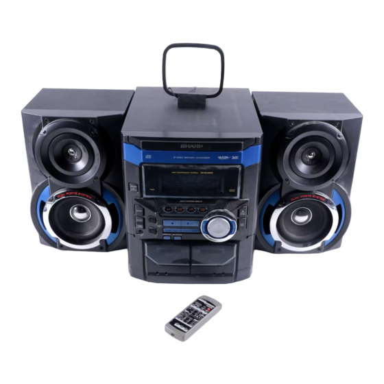
CD-BA250 Mini Component System consisting of
CD-BA250 (main unit) and CP-BA250 (speaker system).
MINI COMPONENT SYSTEM
CD-BA2600
MODEL
CD-BA2600 Mini Component System consisting of
CD-BA2600 (main unit) and CP-BA2600 (speaker system).
• In the interests of user-safety the set should be restored to its
original condition and only parts identical to those specified be
used.
This document has been published to be used
for after sales service only.
The contents are subject to change without notice.
CD-BA250/CD-BA2600
No. S1105CDBA250/
Page
Table of Contents

Related Manuals for Sharp CD-BA250


Summary of Contents for Sharp CD-BA250
-
Page 1: Table Of Contents
SERVICE MANUAL No. S1105CDBA250/ MINI COMPONENT SYSTEM CD-BA250 MODEL CD-BA250 Mini Component System consisting of CD-BA250 (main unit) and CP-BA250 (speaker system). MINI COMPONENT SYSTEM CD-BA2600 MODEL CD-BA2600 Mini Component System consisting of CD-BA2600 (main unit) and CP-BA2600 (speaker system). -
Page 2: Important Service Notes (For U.s.a. Only)
All manuals and user guides at all-guides.com CD-BA250/CD-BA2600 FOR A COMPLETE DESCRIPTION OF THE OPERATION OF THIS UNIT, PLEASE REFER TO THE OPERATION MANUAL. IMPORTANT SERVICE NOTES (FOR U.S.A. ONLY) BEFORE RETURNING THE AUDIO PRODUCT (Fire & Shock Hazard) Before returning the audio product to the user, perform the following safety checks. -
Page 3: Names Of Parts
All manuals and user guides at all-guides.com CD-BA250/CD-BA2600 NAMES OF PARTS CD-BA250/CD-BA2600 Front panel 1. Disc Tray 2. Timer Set Indicator 3. Power On/Stand-by Button 4. Tape 2 Cassette Compartment 5. Tape 1 Cassette Compartment 6. Equalizer Mode Select Button 7. -
Page 4: 1. Remote Control Transmitter
All manuals and user guides at all-guides.com CD-BA250/CD-BA2600 CD-BA250/CD-BA2600 Rear panel 1. FM/AM Loop Antenna Jack 2. Video/Auxiliary (Audio Signal) Input Jacks 3. Speaker Terminals 4. AC Power Cord Remote control 1. Remote Control Transmitter 2. Disc Number Select Buttons 3. -
Page 5: Operation Manual
All manuals and user guides at all-guides.com CD-BA250/CD-BA2600 CP-BA250/CP-BA2600 Speaker system 1. Tweeter 2. Woofer 3. Bass Reflex Duct 4. Speaker Wire OPERATION MANUAL Setting the Clock Press the TUNING/TIME ( or )button to adjust the hour and then press the MEMORY/SET button. - Page 6 Many potential "problems" can be resolved by the owner without calling a service technician. If something is wrong with this product, check the following before calling your autho- Symptom Possible cause rized SHARP dealer or service center. Cannot record. Is the erase-protection tab removed? General Cannot record tracks with proper Is it a normal tape? (You cannot record on a sound quality.
- Page 7 All manuals and user guides at all-guides.com CD-BA250/CD-BA2600 – 7 –...
- Page 8 All manuals and user guides at all-guides.com CD-BA250/CD-BA2600 – 8 –...
-
Page 9: Disassembly
All manuals and user guides at all-guides.com CD-BA250/CD-BA2600 DISASSEMBLY CD-BA250/CD-BA2600 Caution on Disassembly Follow the below-mentioned notes when disassembling (A1)x2 the unit and reassembling it, to keep it safe and ensure Top Cabinet ø3x12mm excellent performance: 1. Take cassette tape and compact disc out of the unit. - Page 10 All manuals and user guides at all-guides.com CD-BA250/CD-BA2600 (K2)x1 Clamp Lever Turntable CD Player Unit (Top View) Cam Gear Rib Slide Chassis (K1)x2 Figure 10-1 (E2)x2 (E4)x1 CD Player Unit Headphones (E1)x2 ø3x10mm Figure 10-4 Power PWB (L1)x3 (E3)x1 (E2)x1...
- Page 11 All manuals and user guides at all-guides.com CD-BA250/CD-BA2600 (N2)x3 Mechanism Loading Motor (N1)x1 (N1)x1 (P1)x5 Figure 11-1 CP-BA250/CP-BA2600 STEP REMOVAL PROCEDURE FIGURE Front Panel 1. Net ......(A1) x1 11-2 Woofer 1. Screw ....(B1) x4 11-3 Tweeter 1. Screw ....(C1) x2...
-
Page 12: Removing And Reinstalling The Main Parts
All manuals and user guides at all-guides.com CD-BA250/CD-BA2600 REMOVING AND REINSTALLING THE MAIN PARTS TAPE MECHANISM SECTION TAPE 2 Perform steps 1 to 6 and 8 of the disassembly method to Record/Playback remove the tape mechanism. Head How to remove the record/playback and erase heads (TAPE 2) (See Fig. -
Page 13: Adjustment
All manuals and user guides at all-guides.com CD-BA250/CD-BA2600 CD MECHANISM SECTION Loading Motor CD Player Perform steps 1, 2, 3, 10,11,12 and 13 of the disassembly Chassis method to remove the CD mechanism. How to remove the loading motor (A1)x1 (A1)x2 (See Fig. -
Page 14: Tuner Section
All manuals and user guides at all-guides.com CD-BA250/CD-BA2600 • FM RF TUNER SECTION Signal generator: 1 kHz, 75 kHz dev., FM modulated fL: Low-range frequency fH: High-range frequency Test Stage Frequency Frequency Setting/ Instrument Adjusting • AM IF/RF Display Connection... -
Page 15: Test Mode
All manuals and user guides at all-guides.com CD-BA250/CD-BA2600 TEST MODE ·Setting the test mode Any one of test mode can be set by pressing several keys as follows.+ + TEST:CD operation test Function:-CD test mode. -Enter test mode. - Page 16 All manuals and user guides at all-guides.com CD-BA250/CD-BA2600 Standard Specification of Stereo System Error MessageDisplay Contents Error Contents DISPLAY Notes Output while Device Protection Operation 'PROTECT' 00: While in Protect Circuit Operate 01: Over Current Detection 02: DC Detection TAPE...
-
Page 17: Block Diagram
All manuals and user guides at all-guides.com CD-BA250/CD-BA2600 DISC CLAMP NUMBER OPEN/ CLOSE T/T UP DOWN LOADING TO MAIN SECTION TO DISPLAY SECTION 43 44 LC78645E CD SERVO XOUT 17 25 CONT5 SLDO SPDO VCC1 M63001FP VCC4 FOCUS/TRACKING/ VCC2 SPIN/SLED +3.3V... - Page 18 All manuals and user guides at all-guides.com CD-BA250/CD-BA2600 IC301 TA7358AP FM FRONT END FM IF 10.7MHz CNP301 T302 CF303 BF301 X351 450kHz CF351 456kHz B.P.F T351 CF352 AM IF FM L312 T301 OSC BUFF IC303 Q302 LA1832S AM TRACKING FM IF DET.
- Page 19 All manuals and user guides at all-guides.com CD-BA250/CD-BA2600 FL701 FL DISPLAY Q701-Q703 RX701 57 56 54 53 52 51 50 49 48 REMOTE SENSOR IC701 VLOAD IX0399AW(1/2) SYSTEM AVDD SW701-SW703 MICROCOMPUTER SW712-SW718 SW720-SW727 SW729-SW732 1 2 4 5 6 7 8...
-
Page 20: Schematic Diagram / Wiring Side Of P.w.board
All manuals and user guides at all-guides.com CD-BA250/CD-BA2600 PICKUP UNIT CD SERVO PWB-C CD SIGNAL VREF VREF 0.047(ML) CNP1 100P 0.0047 (CH) 10/50 100/10 TR– TR– 0.22/50 FO– FO– 100P FO– TR– 0.01 100/10 CD MOTOR PWB-F MUTE SPINDLE SPIN MOTOR SP–... - Page 21 All manuals and user guides at all-guides.com CD-BA250/CD-BA2600 R38 1K 100P R37 1K 100P R36 1K 100P R35 1K R34 1K 100P R33 1K R32 1K 100P 0.022 CNS8 2.2K FROM CD RES DISPLAY PWB CLAMP SW P27 8-A 47(ML) 2.2K...
- Page 22 All manuals and user guides at all-guides.com CD-BA250/CD-BA2600 MAIN PWB-A1(1/3) R601 R-CH R602 A_GND IC601 L-CH CD_GND LC75341 AUDIO PROCESSOR CD_+B A_+B R604 C610 BI601 1/50 CNS601 VREF + – INTERFACE C608 LOUT ROUT Q602 (A_+B) SW_5V KTC3199 GR (ML)
- Page 23 All manuals and user guides at all-guides.com CD-BA250/CD-BA2600 RECORD SIGNAL FM SIGNAL CD SIGNAL PLAYBACK SIGNAL VIDEO SIGNAL C601 75341 ROCESSOR R603 C603 VREF 22/50 + – FACE C607 C609 R605 ROUT 1/50 RBASS R607 3.9K C605 RTRE C611 0.0027...
- Page 24 All manuals and user guides at all-guides.com CD-BA250/CD-BA2600 IC901 STK4029S L-CH R-CH POWER AMP. C939 150P R942 C938 C940 150P 100/50 C936 R934 R944 R938 C935 C946 C945 R949 4.7/50 10/50 10/50 R940 R950 R936 0.1(1W) 0.1(1W) Q904 D913 R952...
- Page 25 All manuals and user guides at all-guides.com CD-BA250/CD-BA2600 MAIN PWB-A1 (2/3) FM SIGNAL CNS971 R969 C967 47/50 M901 D915 R970 FAN MOTOR DS1SS133 R972 C968 R988 HEADPHONES 10/50 R971 R981 PWB-B2 R986 R982 R967 R968 C735 4.7K 4.7K 220P C734...
- Page 26 All manuals and user guides at all-guides.com CD-BA250/CD-BA2600 DISPLAY PWB-B1 FL701 FL DISPLAY 49 48 47 44 43 42 41 40 39 38 37 36 35 34 33 32 31 30 29 28 27 26 25 24 23 16 Q703...
- Page 27 All manuals and user guides at all-guides.com CD-BA250/CD-BA2600 TO CD SERVO PWB P21 12-B CNP8 CNS8 BI701 27 26 25 24 23 16 15 14 13 12 11 10 9 8 7 6 3 2 1 FFC701 C701 1/50 TUN SM...
- Page 28 All manuals and user guides at all-guides.com CD-BA250/CD-BA2600 ANTENNA ANTENNA CNP301 MAIN PWB-A1(3/3) BF301 C301 BAND PASS FILTER 0.01 D305 C303 DS1SS133 C314 10P(CH) 0.0047 C308 4.7P(CH) L312 FM RF C304 0.01 C315 C309 R311 0.01 0.0047 R314 0.001 100K...
- Page 29 All manuals and user guides at all-guides.com CD-BA250/CD-BA2600 AC POWER SUPPLY CORD AC120V/60Hz POWER TRANSFORMER PWB-A3 PT801 POWER TRANSFORMER POWER PWB-A2 F904 2A/125V F901 4A/125V D908 C909 D907 F903 2A/125V D906 ZD903 C902 C901 F902 R905 4A/125V C908 R906 R983...
- Page 30 All manuals and user guides at all-guides.com CD-BA250/CD-BA2600 R373 R378 R388 X352 R372 R374 C382 1 2 3 4 5 6 7 8 9 10 11 R376 C381 IC302 R379 C387 22 21 20 19 18 17 16 15 14 13 12...
- Page 31 All manuals and user guides at all-guides.com CD-BA250/CD-BA2600 TO CD SERVO PWB P34 5-A CNP7 CNS601 1 2 3 4 5 6 MAIN PWB-A1 COLOR TABLE BROWN C620 C616 Q107 RD(R) R137 ORANGE C134 C618 R131 YELLOW C614 R135 GREEN...
- Page 32 All manuals and user guides at all-guides.com CD-BA250/CD-BA2600 DISPLAY PWB-B1 9 10 11 12 13 14 15 16 Q702 CNS8 Q703 Q701 CD SERVO PWB P34 4-A C701 CNP8 R702 C702 R703 R704 RX701 R568 R566 R571 R708 C565 C564...
- Page 33 All manuals and user guides at all-guides.com CD-BA250/CD-BA2600 TO MAIN PWB CNP701 P31 9-H FFC701 23 24 25 26 27 28 29 30 31 32 33 34 35 36 37 38 39 40 41 42 43 44 47 48 49...
- Page 34 All manuals and user guides at all-guides.com CD-BA250/CD-BA2600 P32 1-B P31 8-A FROM FROM DISPLAY PWB MAIN PWB CD SERVO PWB-C CNS8 CNS601 1 2 3 4 5 6 1 2 3 4 5 6 7 8 9 CNP7 CNP8...
- Page 35 All manuals and user guides at all-guides.com CD-BA250/CD-BA2600 P32 4-G TAPE MECHANISM TO DISPLAY PWB ASSEMBLY CNS703 FFC702 TAPE MECHANISM PWB-D SOLENOID SOLENOID TAPE MOTOR TAPE 1 TAPE 2 PLAYBACK HEAD RECORD/PLAYBACK ERASE HEAD HEAD 7 6 5 4 3 2 1...
-
Page 36: Voltage
All manuals and user guides at all-guides.com CD-BA250/CD-BA2600 VOLTAGE IC303 IC701 NO. VOLTAGE NO. VOLTAGE NO. VOLTAGE NO. VOLTAGE NO. VOLTAGE NO. VOLTAGE 3.7V 5.28V 1.6V 1.7V 2.09V 4.77V 1.0V 3.7V 1.7V 5.17V 4.68V 1.6V 1.8V 2.09V 1.8V 2.1V 2.08V 5.25V... -
Page 37: Notes On Schematic Diagram
All manuals and user guides at all-guides.com CD-BA250/CD-BA2600 NOTES ON SCHEMATIC DIAGRAM • Resistor: • The indicated voltage in each section is the one measured To differentiate the units of resistors, such symbol as K and by Digital Multimeter between such a section and the chas- M are used: the symbol K means 1000 ohm and the symbol sis with no signal given. -
Page 38: Waveforms Of Cd Circuit
All manuals and user guides at all-guides.com CD-BA250/CD-BA2600 WAVEFORMS OF CD CIRCUIT Stopped Stopped 1999/04/05 17:33:17 CH1=500mV CH3=500mV 500ms/div CH1=500mV CH3=1V CH4=1V 500ms/div DC 10:1 DC 10:1 (500ms/div) DC 10:1 DC 10:1 DC 10:1 (500ms/div) NORM:20kS/s NORM:20kS/s PDO1 IC1 21... -
Page 39: Troubleshooting
All manuals and user guides at all-guides.com CD-BA250/CD-BA2600 TROUBLE SHOOTING When the CD does not function When the CD section does not operate when the objective lens of the optical pickup is dirty, this section may not operate. Clean the objective lens, and check the playback operation. When this section does not operate even after the above step is taken, check the following items. - Page 40 All manuals and user guides at all-guides.com CD-BA250/CD-BA2600 Stopped (1) Focus-HF system check CH1=500mV CH3=500mV 500ms/div DC 10:1 DC 10:1 (500ms/div) NORM:20kS/s Although a CD is inserted and the cover is closed, "NO DISC" is displayed. Press the OPEN/CLOSE switch (SW1) without inserting a disc, and try starting the playback operation.
- Page 41 All manuals and user guides at all-guides.com CD-BA250/CD-BA2600 (2) Tracking system check Check the TE waveform at pin 15 on IC1. The tracking servo is not activated. If the waveform shown in Figure 41-1 appears and soon after Check the peripheral circuits at pins 14, 15 and 20 on IC1, and NO DISC appears.
- Page 42 All manuals and user guides at all-guides.com CD-BA250/CD-BA2600 (4) PLL system check Stopped 1999/04/05 17:33:17 CH1=500mV CH3=1V CH4=1V 500ms/div DC 10:1 DC 10:1 DC 10:1 (500ms/div) NORM:20kS/s When a disc is loaded, start play operation. PDO1 The HF waveform is normal, but the TOC data cannot be PDO2 read.
-
Page 43: Function Table Of Ic
All manuals and user guides at all-guides.com CD-BA250/CD-BA2600 FUNCTION TABLE OF IC IC1 VHiLC78645E-1: CD Servo (LC78645E) (1/2) Terminal Name Input/Output Setting in Reset Pin No. Function SLC0 Output – Control output. For slice level SLCIST Input – Resistor connection terminal for SLCO output current setting. - Page 44 All manuals and user guides at all-guides.com CD-BA250/CD-BA2600 IC1 VHiLC78645E-1: CD Servo (LC78645E) (2/2) Terminal Name Input/Output Setting in Reset Pin No. Function RVSS – – GND for Right channel. Must be connected to 0V. Right channel RCHO Output LVDD /2 Right channel output.
- Page 45 All manuals and user guides at all-guides.com CD-BA250/CD-BA2600 IC1 VHiLC78645E-1: CD Servo (LC78645E) 80 79 78 77 76 75 74 73 72 71 70 69 68 67 66 65 64 63 62 61 SLC0 DATA SLCIST DATACK EFMIN LRSY ASDFIN...
- Page 46 All manuals and user guides at all-guides.com CD-BA250/CD-BA2600 IC701 RH-iX0399AWZZ: System Microcomputer (IX0399AW) (1/2) Pin No. Port Name Terminal Name Input/Output Function Input (+) POWER SUPPLY -20d BATT Output -20dB ATTENUATOR NO USE Output T_BIAS Output TAPE RECORD BIAS T_T1/T2...
- Page 47 All manuals and user guides at all-guides.com CD-BA250/CD-BA2600 IC701 RH-iX0399AWZZ: System Microcomputer (IX0399AW) (2/2) Pin No. Port Name Terminal Name Input/Output Function P121 NO USE Input P120 PLAY SW_B Input PLAY SWITCH FOR T2 P117 Input TAPE 2 A-SIDE FULL PROOF...
- Page 48 All manuals and user guides at all-guides.com CD-BA250/CD-BA2600 IC601 VHiLC75341/-1: Audio Processor (LC75341) ROUT LOUT LBASS RBASS 0.1uF 0.1uF LTRE RTRE LSEL0 RSEL0 R1 R2 R3 R4 24 23 22 21 20 19 18 17 16 15 14 13 LC75341...
-
Page 49: Fl Display
All manuals and user guides at all-guides.com CD-BA250/CD-BA2600 FL DISPLAY FL701 VVKBJ11LM02T1: FL Display B7 B6 B5 B4 B3 B3 B4 B5 B6 B7 (Hiper) (Lower) – 49 –... - Page 50 All manuals and user guides at all-guides.com CD-BA250/CD-BA2600 –– MEMO –– – 50 –...
-
Page 51: Parts Guide
CD-BA250/CD-BA2600 PARTS GUIDE MINI COMPONENT SYSTEM CD-BA250 MODEL CD-BA250 Mini Component System consisting of CD-BA250 (main unit) and CP-BA250 (speaker system). MINI COMPONENT SYSTEM CD-BA2600 MODEL CD-BA2600 Mini Component System consisting of CD-BA2600 (main unit) and CP-BA2600 (speaker system). “HOW TO ORDER REPLACEMENT PARTS”... - Page 52 All manuals and user guides at all-guides.com CD-BA250/CD-BA2600 PRICE PRICE DESCRIPTION PARTS CODE PARTS CODE DESCRIPTION RANK RANK TRANSFORMERS CD-BA250/CD-BA2600 1 PT801 RTRNP0350AWZZ J BE Power INTEGRATED CIRCUITS T301 RCILB0065AWZZ AC FM OSC. T302 RCILI0017AWZZ AB FM IF VHILC78645E-1 AY CD Servo,LC78645E...
- Page 53 All manuals and user guides at all-guides.com CD-BA250/CD-BA2600 PRICE PRICE PARTS CODE DESCRIPTION PARTS CODE DESCRIPTION RANK RANK AB 22 µF,50V,Electrolytic AA 0.022 µF,25V C125,126 VCEAZA1HW226M J C570~572 VCTYMN1EF223Z AA 0.022 µF,50V AA 0.022 µF,50V C127,128 VCKZPA1HF223Z C573 VCKZPA1HF223Z AA 0.0033 µF,16V AC 220 µF,16V,Electrolytic...
- Page 54 All manuals and user guides at all-guides.com CD-BA250/CD-BA2600 PRICE PRICE DESCRIPTION PARTS CODE PARTS CODE DESCRIPTION RANK RANK R28,29 VRD-ST2CD222J AA 2.2 kohms,1/6W R391,392 VRD-ST2EE271J AA 270 ohms,1/4W VRD-ST2CD822J AA 8.2 kohms,1/6W R393 VRD-MN2BD102J AA 1 kohm,1/8W R31~38 VRD-ST2CD102J AA 1 kohm,1/6W...
- Page 55 AE Holder,Cassette [Tape 2] CNP981 92LCONE5P52287 J AC Plug,5Pin 201- 4 GCOVA1349AWSA J AG Cover,Cassette CNS1A/B QCNWN1537AWZZ J AG Connector Ass’y,7/7Pin [Tape 1 for CD-BA250] CNS2A/B QCNWN1538AWZZ J AG Connector Ass’y,8/8Pin 201- 4 GCOVA1349AWSB J AH Cover,Cassette CNS3A/B QCNWN1539AWZZ J AE Connector Ass’y,6/6Pin...
- Page 56 AA Screw,ø3×10mm (Not Replacement Item) XJBSD30P14000 AA Screw,ø3×14mm 203- 2 PCUSG0022AWZZ J AB Cushion,Leg XJSSD30P10000 AA Screw,ø3×10mm GCAB-1194AWSA AP Cabinet,Top [For CD-BA250] 92LSC0308MBZI AB Screw,ø3×8mm GCAB-1194AWSB AP Cabinet,Top [For CD-BA2600] 92LSC0308RBZI AB Screw,ø3×8mm GCOVA1348AWSA J AH Cover,CD Tray XHBSD40P08000 AA Screw,ø4×8mm...
-
Page 57: Remote Control
PRICE PARTS CODE DESCRIPTION PARTS CODE DESCRIPTION RANK RANK TLABN0112AWZZ AA Label,Serial Number TLABR1180AWZZ AB Label,Bar Code [For CD-BA250] TLABR1181AWZZ AB Label,Bar Code [For CD-BA2600] TLABZ0872AWZZ AC Label,Feature [Tape 1] TLABZ0873AWZZ AC Label,Feature [Tape 2] RRMCG0264AWSA J AQ Remote Control... - Page 58 All manuals and user guides at all-guides.com CD-BA250/CD-BA2600 CD-BA250/CD-BA2600 306-2 306-1 306-3 703x2 305x2 PWB-F Figure 7 CD MECHANISM EXPLODED VIEW – 7 –...
- Page 59 All manuals and user guides at all-guides.com CD-BA250/CD-BA2600 BELT CONNECTION CD-BA250/CD-BA2600 FF/REW FF/REW ROLLER ROLLER Tape 202-1 ASS'Y ASS'Y Motor 603x2 FLYWHEEL FLYWHEEL ASS'Y ASS'Y 610x10 MAIN BELT TAPE1 TAPE2 603x1 610x2 PWB-A1 603x1 610x2 202-2 606x11 M901 PWB-B1 605x2...
- Page 60 All manuals and user guides at all-guides.com CD-BA250/CD-BA2600 CD-BA250/CD-BA2600 607x2 607x2 MECHANISM PWB-E PWB-E 243x4 PWB-C 232x4 Figure 9 CABINET EXPLODED VIEW (2/2) – 9 –...
- Page 61 All manuals and user guides at all-guides.com CD-BA250/CD-BA2600 CP-BA250/CP-BA2600 SP1,2 WOOFER C1,2 Capacitor 2.7µF,100V (N.P.) SP3,4 TWEETER C1,2 SP3,4 Capacitor TWEETER 2.7µF,100V Electrolytic (N.P.) SP1,2 WOOFER SP3,4 909x2 908x4 SP1,2 904x4 906x2 906x2 Figure 10 SPEAKER EXPLODED VIEW – 10 –...
-
Page 62: Packing Of The Set (For U.s.a. Only)
AM/FM Loop Antenna Quick Guide Operation Manual Remote Control SPAKZ0771AWZZ CENTER PAD SSAKA0007AWZZ Polyethylene Bag, Accessories LEFT SPAKZ0773AWZZ RIGHT TOP PAD YELLOW COLOUR BACK SIDE FRONT SIDE OF SPEAKERS SPAKC1138AWZZ [CD-BA250] SPAKC1174AWZZ [CD-BA2600] Packing Case Not Replacement Item – 11 –... - Page 63 All manuals and user guides at all-guides.com CD-BA250/CD-BA2600 –– MEMO –– – 12 –...
- Page 64 All manuals and user guides at all-guides.com CD-BA250/CD-BA2600 © COPYRIGHT 2001 BY SHARP CORPORATION ALL RIGHTS RESERVED. No part of this publication may be reproduced, stored in a retrieval system, or transmitted in any form or by any means, electronic, mechanical, photocopying, recording, or otherwise, without prior written permission of the publisher.