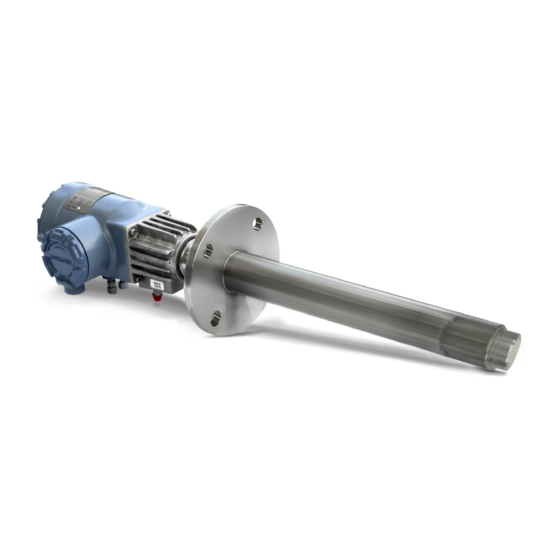
Emerson Rosemount 6888C Quick Start Manual
In-situ combustion oxygen analyzer for use in hazardous areas
Hide thumbs
Also See for Rosemount 6888C:
- Instruction manual (88 pages) ,
- Quick start manual (40 pages) ,
- Manual (86 pages)
Quick Links
See also:
Instruction Manual

Related Manuals for Emerson Rosemount 6888C


Summary of Contents for Emerson Rosemount 6888C
- Page 1 Quick Start Guide 00825-0100-4891, Rev AB October 2019 ™ Rosemount 6888C In-Situ Combustion Oxygen Analyzer For use in Hazardous Areas...
- Page 2 Emerson products. Failure to follow the proper instructions may cause any one of the following situations to occur: loss of life, personal injury, property damage, damage to this instrument, and warranty invalidation.
- Page 3 October 2019 Quick Start Guide The following definitions apply to Warnings, Cautions, and Notices found throughout this publication. WARNING Highlights an operation or maintenance procedure, practice, condition, statement, etc., which if not strictly observed, could result in injury, death, or long-term health hazards of personnel. CAUTION Highlights an operation or maintenance procedure, practice, condition, statement, etc., which if not strictly observed, could result in damage to or destruction of equipment or loss of effectiveness.
- Page 4 Quick Start Guide October 2019 China RoHS Table........................37 Emerson.com/Rosemount...
-
Page 5: Install
Procedure 1. If using the optional ceramic diffusion element, the vee-deflector must be correctly oriented. Before inserting the Rosemount 6888C probe, check the direction of gas flow in the duct. Orient the vee- deflector so the apex points upstream towards the flow. - Page 6 Figure 1-2: 6888C Probe with Integral Autocal Housing Table 1-1: Removal/Installation Probe length DIM A insertion DIM B removal DIM removal depth envelope envelope standard accessory housing housing 18 (457) probe 16.10 (409) 15.77 (401) 19.26 (490) 36 (910) probe 32.52 (826) 46.6 (1182) 50.1 (1271) Emerson.com/Rosemount...
- Page 7 October 2019 Quick Start Guide Table 1-1: Removal/Installation (continued) Probe length DIM A insertion DIM B removal DIM removal depth envelope envelope standard accessory housing housing 6 ft (1830) probe 68.52 (1740) 82.6 (2097) 86.1 (2186) Figure 1-3: Probe Installation Table 1-2: Mounting Flange ANSI Flange diameter...
- Page 8 B. Logic I/O, 4-20 mA signal C. Stack or duct metal wall D. Adapter plate E. Insulation Note Replace insulation after installing Rosemount 6888C. Note Standard housing probe shown. Accessory housing is similar. Probe may be vertical or horizontal. Emerson.com/Rosemount...
-
Page 9: Electrical Installation
October 2019 Quick Start Guide Electrical installation All wiring must conform to local and national codes. Multiple wiring diagrams are shown in this section. Always refer to the diagrams that apply to your transmitter configuration and disregard all other wiring diagrams. WARNING Electrical shock Failure to install covers and ground leads could result in serious injury or... - Page 10 Quick Start Guide October 2019 The Rosemount 6888C accepts line voltage at 120/240 Vac ±10%, 50/60 Hz. No setup is required. 3. Connect the 4-20 mA signal wires at the transmitter. Use a shielded twisted wire pair. Do not allow bare shield wires to contact the circuit boards.
- Page 11 October 2019 Quick Start Guide 2. Pull out the I/O board on the right side of the card rack inside the Rosemount 6888 Xi. If your system is configured to operate two transmitter probes, there are two I/O interface boards. 3.
- Page 12 Pins 2-3 external power Rosemount 6888 Xi to Rosemount 6888 Transmitter (requires 250 Ω resistor across J4, PR+ to PR-). • JP7/JP8: Pins 1-2 internal power Rosemount 6888 Xi to DCS. Pins 2-3 external power Rosemount 6888 Xi to DCS. Emerson.com/Rosemount...
- Page 13 October 2019 Quick Start Guide Figure 1-7: Wiring Diagrams - Single/Dual Channel Wiring Diagram A. Power supply board B. Channel #2 IO board C. Shield ground D. Channel #1 IO board E. AC input to P/S F. Plug G. Channel #2 alarm relay SPS/IMPS H.
- Page 14 2. Connect the line (L1 wire) to the L1 terminal, the neutral (L2 wire) to the L2/N terminal, and the ground wire to the ground lug. The Rosemount 6888C accepts line voltage at 120/240 Vac ±10%, 50/60 Hz. No setup is required.
- Page 15 October 2019 Quick Start Guide Figure 1-8: Integral autocal and HART communications A. Ferrite clamp B. Signal C. Test points D. #8 pan htd scr (internal ground) E. Power F. Test point group Note A. Except for JP5, JP7, and JP8 on IO board, jumper and switch settings are factory set and are shown for reference only.
- Page 16 2. Connect the line (L1 wire) to the L1 terminal, the neutral (L2) wire to the L2/N terminal, and the ground wire to the ground lug. The Rosemount 6888C accepts line voltage at 120/240 Vac ±10%, 50/60 Hz. No setup is required.
- Page 17 October 2019 Quick Start Guide Figure 1-9: Integral Autocal and F Fieldbus Communications OUNDATION without Optional Rosemount 6888 Xi A. Signal B. Not used C. #8 pan htr scr (internal ground) D. Power E. Probe test point group Quick Start Guide...
- Page 18 (Used as a communication bus from probe transmitter electronics to optional Rosemount 6888 Xi. Not accessible to Field Communicator or AMS) D. #8 pan htr scr (internal ground) E. Power F. Probe test point group IO board switch/jumpers Jumper settings • JP1: Pins 2-3 Emerson.com/Rosemount...
- Page 19 October 2019 Quick Start Guide • JP2: Pins 2-3 • — Pins 1-2 internal power — Pins 2-3 external power • — Pins 1-2 internal power — Pins 2-3 external power • — Pins 1-2 internal power — Pins 2-3 external power SW4 switch settings •...
- Page 20 I. Channel #1 alarm relay, SPS/IMPS J. Channel #1 4-20 mA/HART output 1.2.5 Connect traditional architecture system to the direct replacement probe Use a traditional architecture configuration to provide for remote location of the transmitter electronics. All electronics are housed inside the Emerson.com/Rosemount...
- Page 21 October 2019 Quick Start Guide ™ Rosemount 6888 Xi. A multi-conductor power/signal cable connects the probe to the Rosemount 6888 Xi. Use the following procedure to connect the traditional architecture probe to the Rosemount 6888 Xi. Note The traditional architecture cable is provided at the specified length and is ready for installation.
- Page 22 B. All wiring marked with an asterisk (*) is factory wiring inside the Rosemount 6888 Xi. C. Except for JP7 and JP8 on IO board, jumper and switch settings are factory set and are shown for reference only. Emerson.com/Rosemount...
- Page 23 October 2019 Quick Start Guide Figure 1-13: Wiring Diagrams - Traditional Architecture with Direct Replacement Probe (no Electronics Inside) A. Power supply board B. DR board C. Shield ground D. IO board E. Plug F. Probe cable G. AC input H.
- Page 24 Calibration reading errors Failure to use proper gases will result in erroneous readings. Do not use 100% nitrogen as a low gas (zero gas). Emerson suggests that gas for the low (zero) be between 0.4% and 2.0% O Do not use gases with hydrocarbon concentrations of more than 40 parts per million.
- Page 25 October 2019 Quick Start Guide Figure 1-14: Rosemount 6888C Calibration Gas Connections A. Calibration gas in B. Reference air vent C. Reference air in Quick Start Guide...
-
Page 26: Configuration, Startup, And Operation
Rosemount 6888 Xi Electronics. Procedure 1. Apply AC line power to the transmitter. 2. Apply AC line power to the Rosemount 6888 Xi. Run the Quick Start Wizard as described below. At the Auto Cal Device screen, select the Emerson.com/Rosemount... - Page 27 October 2019 Quick Start Guide calibration method based on the Rosemount 6888 Transmitter as follows: • Standard Probe Housing Configuration: Select None, SPS, or IMPS as appropriate. Do not select Integral or calibration will not be possible. • Integral Autocal Probe housing: Select Integral only. If you don't select Integral, calibration will not be possible.
- Page 28 Refer to the Rosemount 6888 Xi Reference Manual for calibration setup details. , use the Up and Down keys 8. When prompted by Setup Correct? to select Yes. If you select No, the wizard restarts. 9. Press Enter to continue. Emerson.com/Rosemount...
- Page 29 HART communications to a Field Communicator or AMS console. The technician needs to manually switch the gases based upon these prompts. Emerson recommends using 0.4% O and 8% O , balance nitrogen as calibration gases. Always use a two-stage pressure regulator set to 20 psi.
- Page 30 The factory offers a probe rebuild capability if solenoid or other failures occur. CAUTION Leaks Calibration gas bottles ARE piped and under pressure at all times, so be sure to leak-check all fittings, tubing, and connections. Always use dual-stage pressure regulators. Emerson.com/Rosemount...
-
Page 31: Rosemount ™ 6888 Product Certifications
Rev 1.9 European Directive information The most recent revision of the EU Declaration of Conformity can be found at Emerson.com/Rosemount. Ordinary location certification As standard, the transmitter has been examined and tested to determine that the design meets the basic electrical, mechanical, and fire protection requirements by a nationally recognized test laboratory (NRTL) as accredited by the Federal Occupational Safety and Health Administration (OSHA). - Page 32 EN 60079-0:2012/A11:2013, EN 60079-1:2014 Markings II 2 G Ex db IIB+H2 T3 Gb; IP66; -40 °C ≤ Ta ≤ +70°C ( Autocal Housing and Probe assembly); -40 °C ≤ Ta ≤ +90°C (Standard Housing and Probe assembly eq. “DR Probe”) Emerson.com/Rosemount...
- Page 33 October 2019 Quick Start Guide Special conditions for safe use (X): 1. Mounting flange temperatures shall not exceed 190 °C during combustion process. 2. The 6888C O Analyzers are used with the 6888 Xi Advanced Electronics (associated equipment not part of this certification) which must be installed in a Safe Area.
- Page 34 Quick Start Guide October 2019 Emerson.com/Rosemount...
-
Page 35: Declaration Of Conformity
October 2019 Quick Start Guide Declaration of Conformity Quick Start Guide... - Page 36 Quick Start Guide October 2019 Emerson.com/Rosemount...
- Page 37 October 2019 Quick Start Guide China RoHS Table Quick Start Guide...
- Page 38 Quick Start Guide October 2019 Emerson.com/Rosemount...
- Page 39 October 2019 Quick Start Guide Quick Start Guide...
- Page 40 Linkedin.com/company/Emerson- Automation-Solutions The Emerson logo is a trademark and service mark of Emerson Electric Co. Rosemount is a twitter.com/rosemount_news mark of one of the Emerson family of companies. Facebook.com/Rosemount All other marks are the property of their youtube.com/RosemountMeasurement respective owners.