Table of Contents
Quick Links
Table of Contents

Related Manuals for NEC IPASOLINK 400

Summary of Contents for NEC IPASOLINK 400
- Page 1 NEC IPASOLINK 400 INSTALLATION AND PROVISIONING © Pekka Linna NEC Finland Oy 2012...
-
Page 2: Table Of Contents
CONTENTS INTRODUCTION ........................6 PRODUCT DESCRIPTION ..................... 6 400 ........................7 IPASOLINK COMPATIBLE OUTDOOR UNITS ..................8 NHG ............................. 8 NHG2 ............................. 8 ............................. 9 BLOCK DIAGRAMS ........................ 9 AVAILABLE CONFIGURATIONS ..................11 UNPROTECTED HOP ....................... 11 PROTECTED CONFIGURATIONS ................. 11 1+0 .............. - Page 3 INDOOR UNIT CONFIGURATIONS ................... 25 ORDERING CODES ......................26 PREINSTALLED LICENSES ....................26 SAFETY ISSUES ........................26 ..............26 OPEN WAVEGUIDE AND OPTICAL CONNECTORS ..................26 AVOID THE FRONT OF THE ANTENNA RADIATION MONITORING DEVICES ................27 SAFETY DISTANCE FOR THE PUBLIC EXPOSURE ..........27 INDOOR UNIT INSTALLATION ..................
- Page 4 ....................36 IDU AND CABLE LABELLING ....................36 OVERVOLTAGE PROTECTION LOCAL MANAGEMENT ....................... 37 MANAGEMENT TOOL ....................... 37 ....................37 RECOMMENDED BROWSER ......................37 LOCAL CONNECTION .................. 38 REMOTE LOGIN USING THE BROWSER LOGIN WINDOW ........................ 38 – ................. 39 MAIN PAGE MENU AND CURRENT STATUS ..................
- Page 5 ....................... 73 SAMPLE VLAN SETTINGS QOS SETTINGS ........................76 TRAFFIC CLASSIFICATION PRINCIPLES ..............76 SAMPLE QOS POLICY...................... 79 QOS SETTINGS – CLASSIFY AND INGRESS POLICING .......... 80 ......................82 PORT QOS SETTINGS ..................... 84 QOS SETTINGS SUMMARY COPYING SETTINGS FROM ONE IDU TO ANOTHER ..........85 PRECONFIGURATION FILES .....................
-
Page 6: Introduction
Moreover, the microwave hop has to be planned according to current ITU-R methods in order to ensure sufficient margin against fading. NEC iPasolink uses the traditional split mount installation method: indoor unit (IDU), coaxial cable, outdoor unit (ODU) and antenna. Different products of the iPasolink 100/200/400/1000 family may interface over the air with certain limitations regarding maximum modulation. -
Page 7: Ipasolink 400
IPASOLINK 400 This guide is based on the middle-sized member of the family, the iPasolink 400. It may contain up to four (4) modems. Each modem can provide Ethernet L2 capacity 10 to 400 Mbit/s or PDH/SDH capacity up to 152 x E1 or 2 x STM-1 or various combinations. -
Page 8: Compatible Outdoor Units
In the unit in Fig. 1 two modems (left) and a GbE interface card (right) have been installed. The unused slot is covered by a blank cover. In the lower part are (from the left): the main card, a power supply, an unused power supply slot and the fan unit. -
Page 9: Ihg
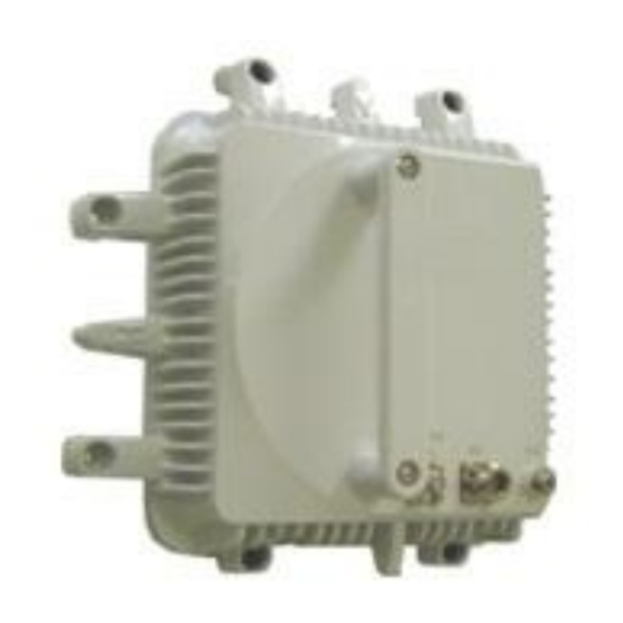
IHG FW version should be 5.08 or later. IHG will then work with iPasolink and PASOLINK NEO. BLOCK DIAGRAMS The block diagram of iPasolink 400 Indoor Unit (IDU) is presented in Figure 3. The Outdoor Unit (ODU) is described in Figure 4. - Page 10 Figure 3. iPasolink 400 IDU, block diagram. Figure 4. IHG ODU, block diagram. The Outdoor Unit (ODU) generates the final microwave signal using the IF signal from the IDU by upconverting it one or two times (MIX). The output of the mixer is band-pass filtered (BPF) in order to remove the unwanted mixing products and then power amplified (PA).
-
Page 11: Available Configurations
AVAILABLE CONFIGURATIONS UNPROTECTED HOP The most basic configuration is a 1+0 or unprotected hop between a pair of modems. A single iPasolink 400 IDU can have up to four (4) 1+0 connections to separate sites. In this maximum configuration four ODUs, four antennas and four coaxial cables are needed together with one IDU and four modems. -
Page 12: Configuration Diagrams
LAG method. Several streams (e.g. different MAC DA or SA) are needed in order to use the full capacity. The more advanced NEC proprietary L1 aggregation (Physical RTA, PRTA) method will create a genuine combined Ethernet port towards the air and even a single Ethernet stream can use the full capacity. - Page 13 Figure 6. Additional configurations. Figure 6 shows on the top a HS/SD solution using four antennas per hop. This is the best solution for long hops: no loss of fade margin and switching is hitless in both directions. The middle solution is 2+0, i.e. two working channels and no protection channel. However, considering Ethernet traffic, 2+0 has some protection against a single equipment failure.
- Page 14 Figure 7. XPIC configurations. Figure 7, top, shows a basic XPIC 1+0 (could be called XPIC 2+0 as well). It uses a single channel pair, two polarizations and four modems per hop over a single antenna per site. Double capacity is achieved without using any extra spectrum.
-
Page 15: Asymmetrical Hops
ASYMMETRICAL HOPS Often the two ends of the hop are identical. But it is possible to use a different IDU (e.g. iPasolink 400 or 1000 in the aggregation node and iPasolink 200 or 100 in the remote end). The interface type can be different (e.g. -
Page 16: Ipasolink Capacity
Figure 8. Typical Ethernet frame. Preamble, Start of frame delimiter and Interframe gap (L1 overhead) are never transmitted over the air. Optionally also MAC destination and Mac source adresses may be compressed. The highlighted octets (20 octets) in Figure 8 are removed and instead three octets are added for internal purposes. - Page 17 L1 capacity L2 capacity Frame size (L2 octets) (Mbit/s) (Mbit/s) 1000 761,9 1500 1000 986,8 8000 1000 997,5 Table 2. GbE interface L2 capacity also depends on the frame size. If the average frame size were only 64 octets, there would be a problem fitting the 2+0 maximum capacity at 56 MHz and 512QAM into a single GbE interface.
-
Page 18: Qos And Overprovisioning
QOS AND OVERPROVISIONING If the traffic coming to the IDU is very bursty and time-variable, so called “overprovisioning” (or “overbooking”) of the radio is a possible method for cost savings. Due to the statistical variation and the fact that the traffic peaks seldom occur simultaneously. The combined traffic has a peak value less than the sum of the peak values of contributing interfaces. - Page 19 design is of course based on the empirical rain and multipath fading models for the average worst month. No real guarantee for the availability due to weather conditions can be given, but statistically the designed hops will meet the targets. A more expensive solution would be to design the hop for 99,999% availability for the full 256QAM 366 Mbit/s.
-
Page 20: Main Specifications
MAIN SPECIFICATIONS The following tables present the main technical specifications of the iPasolink 400 equipment. Some performance data are given in Appendix A. ODU frequency bands 6, 7, 8, 10, 11, 13, 15, 18, 23, 26, 28, 32, 38, 42 GHz ... - Page 21 Physical RTA: maximum speed per stream equal to combined capacity minus a small overhead Synchronous Ethernet Supported (optional clock module required) TDM PWE RFC4533 SAToP (MEF8) Other Link Loss Forwarding, Mirror/Monitor, Broadcast Storm Control, L2 Filter, Port Isolation Table 5. iPasolink 400 Ethernet-switch main characteristics...
-
Page 22: Idu Configurations
Limitation: the SFP modules installed in each MC-A4, GbE-A or STM1-A SFP port have to be identical or the right port empty. Third party SFP modules do not generate an alarm (note: FW version dependent) but correct operation is guaranteed only for an SFP delivered by NEC. - Page 23 Figure 10 presents the plug-in unit configurations in the indoor unit and Figure 11 depicts the plug-in units. Figure 10. Indoor unit NWA-055268-001 and its ODU connection Figure 11. Universal Slot-modules/cards. Note: Modem-A module: the old HW-version has no ONLINE led.
-
Page 24: Pdh-Interfaces
PDH-INTERFACES The control unit (main card) MC-A4 and 16E1-A-card MDR68-connector and pin layout is identical with the Pasolink NEO HP AMR MDR68-connector. See Appendix B and the section on ”PDH provisioning”. MANAGEMENT AND AUXILIARY INTERFACES MC-A4- and/or AUX-A-card (optional) provide the following management and auxiliary interfaces (Table 7). Interface Description MC-A4... -
Page 25: Indoor Unit Configurations
INDOOR UNIT CONFIGURATIONS Figure 12. Modem positions for various single and dual IDU setups Figure 12 presents a summary on possible modem positions when using a single or dual IDU setup. For additional detais, see the Ordering Guide. -
Page 26: Ordering Codes
See the Price List and the Ordering Guide for the ordering codes. PREINSTALLED LICENSES When agreed between the customer and NEC, the IDU may have all the licenses preinstalled. Certain functionalities are then always paid for and available for immediate use. Certain functions require additional payment before use. -
Page 27: Radiation Monitoring Devices
RADIATION MONITORING DEVICES It is recommended that the installation crews use personal radiation monitoring devices. They are most useful when working close to high power HF/VHF/UHF transmitting antennas, in order to ensure that power has been switched off or reduced to a safe level. There are no cumulative long-term radiation effects known for non-ionizing radiation such as microwaves. -
Page 28: Indoor Unit Installation
One should be aware that the worst hot spot is usually 1 to 3 antenna diameter from the antenna aperture on the antenna symmetry axis. Another rule of thumb is that the maximum intensity is larger for a smaller antenna. The most dangerous “antenna” is an open waveguide (i.e. very small radiating aperture). The safety zone for a large antenna can be very long but the maximum intensity much lower than in case of a small antenna. -
Page 29: Power Connection
POWER CONNECTION The indoor unit PS-A4 card -48V connector should be connected to a 10A fuse or automatic circuit breaker. This is sufficient when using a 2 x 1.5mm2 power cable and takes into account the fact that the current will increase when the battery voltage drops. -
Page 30: Ethernet Cable Connections
Figure 14. Connector pin. The two guide blades (at the centre of the pin pointing upwards) should not be bent. Crimp the insulation blades and the conductor barrel only. ETHERNET CABLE CONNECTIONS The Ethernet cabling is done in the usual manner: electrical using Cat6 cables and optical using LX-type cables with LC-connectors. -
Page 31: 6 Ghz Odu With Standard Waveguide
license). Note that all ODUs on the same site have to be either HIGH or LOW, if they use the same frequency band. The ODU version is indicated as HIGH or LOW on the box and on the ODU label. ... -
Page 32: Separate Installation Of 7 And 13 Ghz Direct Mount Odu
The “antenna direct mount” type ODUs for 7 GHz and 13 GHz are possible to install directly to the antenna using the NEC proprietary antenna interface. It is also possible to use a separate installation using a waveguide. The ODU installation bracket will then have an adapter from NEC interface to the appropriate IEC standard waveguide interface. - Page 33 Figure 17. 13 GHz ODU attached directly to a 0.6m antenna. NHG type ODU; the IHG antenna interface is identical. The antenna delivery includes two different O-rings. For direct mount, the larger O-ring has to be used. The smaller one is for attaching a flexible waveguide in a separate installation. Both O-rings must not be used. Figure 18 below depicts the antenna flange.
-
Page 34: Odu Cable Installation
Figure 19. Changing the polarization. Details vary depending on the antenna version. In order to change the polarization of the antenna, the antenna feed has to be turned by 90 degrees. The feed screws are opened slightly to allow turning of the feed. Note: when the waveguide opening is horizontal (broadside up) the polarization is vertical. -
Page 35: Cable Connectors
The maximum cable length when using the above Draka cable as an example is about 500m, which includes an allowance for the higher per unit attenuation in the tail cables. Cables should be marked as required by the tower/shelter owner. Cables should be attached using proper permanent cable brackets –... -
Page 36: Grounding In The Shelter
Grounding wires should be installed as straightforward as possible, avoiding bends and loops GROUNDING IN THE SHELTER Grounding of the lower end of the ODU cable should be done at the connection between the ½-inch cable and the tail cable as close as possible to the wall feed-through point to the nearest grounding bar or wire using as short 16 mm2 Cu cable as possible. -
Page 37: Local Management
LOCAL MANAGEMENT MANAGEMENT TOOL The indoor unit is managed using a PC and a standard web browser. Note. The previous generation (Pasolink NEO) LCT and PNMTj software are not compatible with iPasolink nor are there any such versions available. RECOMMENDED BROWSER Firefox is the recommended browser, because the ”Menu Bar”... -
Page 38: Remote Login Using The Browser
When the DHCP server has given the LAN card an IP address, the default gateway indicated for the LAN card is the LCT port (and the web page) address. The address is easy to check by running cmd and typing ipconfig. -
Page 39: Main Page - Menu And Current Status
MAIN PAGE – MENU AND CURRENT STATUS The page opened shows the Menu tree and the Current Status of the IDU. Figure 25. Current Status –window shows the active alarms after pressing Refresh. In order to allow changing of the settings immediately, the status window is not updated until the Refresh is clicked (FW 3.00.37 and later). -
Page 40: Provisioning Clear
Note: if suitable basic configuration files are first copied to each IDU, following the Quick Installation Guide (Appendix D) is sufficient. The basic configuration files should contain all the default settings for the operator. Then only those settings that vary from each NE to NE need to be changed during installation. PROVISIONING CLEAR If the IDU is not at the factory settings, it may be useful to return all Provisioning Settings to factory settings using Equipment Utility ->... - Page 41 Figure 27. Equipment Configuration. Use Setup button to modify. NE Name – Give IDU name (e.g. Site Name – IDU – IDU#). Maximum 32 characters, no special characters! Element setting. Figure 27. NE Name.
- Page 42 Equipment Configuration – Select the cards (press Auto Detect), if necessary disable by selecting ”Not used” for cards that should not be used. Note that cards should not be removed physically due to EMC and IDU cooling reasons unless a blank cover is installed. Element setting. Figure 28.
- Page 43 RADIO CONFIGURATION Equipment Setup -> Radio Configuration -> Setup Figure 29. Radio Configuration Setup The thin green frame in the left upper corner indicates which modem is being set up. Unfortunately the modem port name is not shown in this window (shown in the Ethernet settings only). ”ODU Information” shows the available settings of the ODU connected currently.
- Page 44 Reference modulation: This selection determines the maximum available power. In order to get maximum power at QPSK, select Reference Modulation = QPSK. Element setting. Note. The transmitter power depends on a) MTPC setting and b) current modulation. When the reference modulation is QPSK, the MTPC setting allows selecting the maximum power.
- Page 45 Radio Traffic Aggregation – aggregating the Ethernet capacity of two modems operating on the same hop. Hop setting. Figure 30. Radio Configuration changes confirmed by OK. Settings continue with AMR settings.
- Page 46 ADAPTIVE MODULATION RADIO (AMR) Equipment Setup -> AMR/Radio Mapping Configuration, Setup Figure 31. Adaptive modulation (AMR) settings. Example: license allows 32QAM, 16QAM and QSPK. If antennas have not been aligned, select AMR Non Operation. Adaptive modulation changes the transmit power slightly which would cause problems during the alignment. After the alignment is ready remember to select AMR Mode (Used) for the appropriate modulations.
-
Page 47: Network Management (Nms) Settings
NETWORK MANAGEMENT (NMS) SETTINGS Figure 33. Typical NMS subnet The root element (Root NE) is the indoor unit where this cluster is connected to the NMS DCN using the NMS port (or in band connection). The rest of the cluster is connected internally or by connecting NMS ports together at the intermediate sites. - Page 48 Figure continues on the next page.
- Page 49 Figure 34. NMS settings. NE2 Port Setting: NE2 is on the AUX-A card, a serial port used when interfacing some legacy equipment. Default Not Used. In band Management VLAN Setting - Default “Not Used”. The settings here assume that NMS port is used for management.
- Page 50 Note that the LCT port can also used for pinging the NMS server using the standard PC settings for local management, i.e. using the local IP address given by the DHCP server of the LCT port. NE Branch Setting – If the network elements are in a different subnet than the NMS port or if the NMS port or NE1 port is used for connecting another subnet then the element is configured as a router.
-
Page 51: Modem Settings
Equipment Setup -> Network Management Setting -> IP Access Control Setting Do not change the settings. Empty list means that any PC connected to any IP address can manage the element remotely. Default setting. Equipment Setup -> Network Management Setting ->Equipment Cascade setting Do not change the settings. -
Page 52: Synchronization Setting
0 dBm = -30 dBW Note. The previous generation NEC Pasolink NEO used power setting in “dB relative to the maximum available power”. RX Threshold: use the default setting -50 dBm. This is the target minimum received level, below which the opposite end transmitter power will be increased when ATPC is in use. - Page 53 If both ends are Master-Master or Slave-Slave, the connection will be unstable: errors and/or Unlocked alarms. The element management may report ”Communications Error” when using the web browser. Note. If a chain contains several iPasolink sites and the intermediate site is using a single IDU (two modems per IDU), then the first IDU of the chain on the core network side should be Master and all the other IDUs Slaves synchronized to the modem towards the Master.
- Page 54 Figure 38. Master setting without the Clock Module. SYNCHRONIZATION SETTINGS WITH THE CLOCK MODULE The settings are presented in Fig. 39 and 40. Figure 39. Master setting with the Clock Card -option. Equipment Clock Setting – MASTER Equipment CLK Mode: Master Clock Source Selective Mode: QL Mode (Quality level).
-
Page 55: Date And Time Setting
Clock Source Selective Mode: PL Mode (Priority Level). (QL Mode could be used as well). Select No.1 Line CLK (MODEM), and the Slot number where the modem towards Master is installed and select Priority Level = 1. In case of 1+1, select the two modems for Priority level 1 and 2. Figure 40. -
Page 56: Network Management Security Settings
NETWORK MANAGEMENT SECURITY SETTINGS User Account/Security Setting -> Security Management -> Service Status Setting Figure 42. Status of the management related services ”Service Status” window should look like Figure 42. Other services should be running except for the SFTP and HTTPS stopped. Figure 43. - Page 57 Figure 44. SNMP Community settings (no access control). SNMP Community. Default setting: public/Admin/Access Control Disable (0.0.0.0/0.0.0.0). The first line can be edited using the link 1. The Community name has to be the same as in the PNMSj settings (public). Access Level = Admin. Source IP and mask 0.0.0.0 means that the Access Control is Disabled).
- Page 58 NTP SETTINGS FOR THE ROOT ELEMENT User Account/Security Setting -> Security Management -> Service Status Setting Figure 45. NTP settings for the root element when the NTP server is at 192.168.180.36. Most accurate time stamping of the events and logs etc. requires that an NTP server is available for the root elements.
- Page 59 NTP SETTINGS FOR NON-ROOT (NORMAL) ELEMENTS User Account/Security Setting -> Security Management -> Service Status Setting Figure 46. NTP settings for normal elements. NTP server is the root element modem (Bridge1) IP address. For other elements than the root element the NTP Server Address is the root element Bridge1 address. The NTP Server Mode is now Disabled.
- Page 60 OTHER SERVICES User Account/Security Setting -> Security Management -> Service Status Setting Figure 47. FTP, SFTP, HTTP and HTTPS service settings Note that the HTTP service should never be disabled as the web interface will be disabled and restoring this setting would be impossible remotely. The SFTP and HTTPS services should be Stopped (either HTTP or HTTPS should be running, not both).
-
Page 61: Antenna Alignment
ANTENNA ALIGNMENT The basic settings described in the previous chapters should be done before the antenna alignment. Before the alignment some temporary settings are required for correct receive level indication. ALIGNMENT SETTINGS If the element is already connected to the NMS server, set Maintenance on (Current Status top of page). - Page 62 Figure 49. Typical connector voltage vs. receiver level at the ODU antenna port A typical mistake during the alignment is to find the first side lobe of the pattern. Note that the side lobes are circular around the round main lobe, when looking behind the antenna. The minima between the maxima are also circular.
-
Page 63: Management Network
Equipment Utility/Log Clear Function. MANAGEMENT NETWORK The management system for NEC Pasolink/iPasolink called PNMSj. Alternatively the more generic MS5000 can be used. The DCN is based on Ethernet/IP/TCP/UDP/SNMP. Each cluster of radio links is usually connected to the NMS DCN at one IDU (the root element). - Page 64 NEO using the NMS port has to have “Connect NMS port to NMS” set to “Yes”. In case of iPasolink 400 single IDU repeater (all three modems in a single IDU) the NMS connection is internal and all modems are connected to Bridge1.
-
Page 65: Dcn Over Pdh/Sdh
DCN OVER PDH/SDH If there is no Ethernet/IP DCN network available to any station in the iPasolink cluster, it is possible use PDH network for DCN (“Ethernet over PDH”). At least one E1 should be dedicated to the NMS traffic per iPasolink cluster. -
Page 66: Provisioning Pdh
PROVISIONING PDH Provisioning -> E1/STM-1/Cross Connect Setting -> E1 Port Setting Figure 54. E1 ports have to be enabled at the main card (MC-A4) connector. Modify button allows to enable the MDR68 connector E1 ports to be used. Select the impedance (usually 120 ohms symmetric pair connected to the external cross-connect frame). - Page 67 E1 channels have to be enabled in the modem (in the AMR settings) and the connector ports enabled in the connector as shown above. In addition, these two have to be cross-connected together. Modem channels can also be connected to another modem so that these E1s are not available at the external connector but are transmitted directly to the next hop.
- Page 68 Select one channel on the Edge A side and another on the Edge B side and press OK. Repeat for additional connections. Block selection is also possible. Element setting. Note. Under Equipment Setup -> AMR/ Radio Mapping Configuration the number of E1 channels carried by the radio were set for each AMR level.
-
Page 69: Ethernet Settings
ETHERNET SETTINGS Provisioning -> ETH Function Setting The Menu contains numerous L2 switch settings under Eth Function Setting. This chapter describes the most common settings only. Interface numbering Ethernet ports are identified by the main card (MC-A4) or by the card type/slot number (GbE-A/Slot 1) as well as the port number (Port01). -
Page 70: Vlan Settings
Figure 59. In this figure MC-A4 2nd port has been given a name ”TRUNK” and it has been enabled. The cable is disconnected (Link Down). The correct Ethernet settings depend on the external equipment settings. Figure 60. GbE settings. Note. Optical SPF allows selecting ”Electrical” but that will cause an alarm. VLAN SETTINGS VLAN Setting ”VLAN List”... - Page 71 Figure 61. VLAN settings. The VLANs can be assigned to ports in the VLAN Setting tab. Figure 62. Example VLAN settings. Each external port has a tunnel VLAN and the modem port allows traffic of these VLANs (as trunks). VLAN Port Type setting selects how the incoming (Ingress) and outgoing (Egress) frames are handled. The VLAN port types are explained first.
-
Page 72: Bridge Modes (802.1Q And 802.1Ad)
BRIDGE MODES (802.1Q AND 802.1AD) Bridge mode (aka VLAN mode) is selected under Bridge Setting. The VLAN port types are as follows: 802.1q type Ingress port action Egress port action Access port Adds the assigned tag if Will not forward the no incoming tag. -
Page 73: Sample Vlan Settings
It is possible to create several VLAN ports in the same physical port with certain limitations. As an example, 802.1q trunk-port (VID= 100) and access-port (VID=200) may coexist in an Ethernet port. The port will then accept VID=100 tagged frames as well as VID=200 tagged frames. All untagged frames will also be accepted and a tag with VID=200 is added to them. - Page 74 Any frame (untagged, single tagged, dual tagged or multiple tagged) arriving at a Tunnel port will be added the assigned VLAN ID and be sent to the opposite end over the modem port. If the opposite end has a fully identical VLAN setup, the traffic will egress at the same port as the original port without the added tag (same frame as the original frame with any customer VID).
- Page 75 Figure 67. Settings for Figure 66 trunk Ethernet port. All three VLANs are assigned to the same trunk port (MC-A4 Port 02). FDB Setting Forwarding Data Base contains the L2 switch MAC-address settings. Retrieve Current FDB – check and store the MAC-addresses e.g. for trouble shooting. Use a Microsoft application to open the file (e.g.
-
Page 76: Qos Settings
QOS SETTINGS Provisioning - > Ethernet Function Setting -> QoS/Classification Setting Each port of the iPasolink L2 switch can be configured for certain QoS settings. The next section describes the principles of iPasolink QoS operation in general. TRAFFIC CLASSIFICATION PRINCIPLES The functional QoS block diagram of the IDU is presented in Figure 68 below. - Page 77 Block Function Setting Description Notes IC (Internal Classify (map) the Classify Profile Assign internal priority Equipment Based Mode: one user Classifier) ingress frame to Entry based on CoS (p-bit) or defined mapping profile common to all internal priority IP v4/v6 DSCP or MPLS ports based on CoS p-bit.
- Page 78 The Qos processing of frames consists of four phases from ingress port (e.g. Ethernet port) to egress port (e.g. modem port). The process is similar in the reverse direction but the QoS settings may be totally different (Figure 68). 1) Incoming or ingress frames are classified into an internal priority value (”IC” in Figure 68) based on ...
-
Page 79: Sample Qos Policy
3) In the third phase each internal priority is mapped in on of 4 or 8 Egress Queue Classes. The setting is per ingress port but the different mappings is limited to three (one default one-to-one and two user configurable). ”EC” in Figure 68. 4) Based on the ingress port settings the frame (Green, Yellow or Red) will be switched to the egress port based on the VLAN assignments. -
Page 80: Qos Settings - Classify And Ingress Policing
QOS SETTINGS – CLASSIFY AND INGRESS POLICING Figure 69. Classification Mode: port based QoS and CoS(C-tag)-mode. Select Port Based QoS Mode. Select CoS (C-Tag) Port Classification Mode for all ports. Figure 69. Default Port Priority = 0 for untagged frames. Ingress Policer –settings are left empty. - Page 81 Figure 71. Add Policer Index: here Policer Profile would be selected if necessary. Under Provisioning -> ETH Function Setting -> QoS / Classification Setting -> Port Setting the Class Mode is selected, following the example 8 classes. Figure 72. This setting is common for all ports including the modem.
-
Page 82: Port Qos Settings
PORT QOS SETTINGS The settings for the QoS policy example are described here. Table 16 shows one-to-one mapping from CoS to internal priority which is the default setting in the Port Based QoS Mode and cannot be changed in this mode. The settings for each ingress port have to be modified: mapping from internal priority to egress queue class, scheduling, shaping and WRED-settings. - Page 83 Shaper Rate = 1000M in all classes (= no speed limit). DWRR (Deficit Weighted Round Robin) Weight defines the capacity usage between the classes (excluding SP class). The sum of the weights is 1+5+28+89+3 = 127, therefore Class 0 gets 1/127 = 0,79% of the capacity left after SP-class frames are transmitted, in the case when there is congestion.
-
Page 84: Qos Settings Summary
In the top part of Figure 76 Port Setting are the egress queue settings for this port. This setting affects the frames going out of the equipment. In the middle in Figure 76 (with the complex heading) are the settings affecting the incoming (ingress) frames to this port, i.e. -
Page 85: Copying Settings From One Idu To Another
COPYING SETTINGS FROM ONE IDU TO ANOTHER Manual setup of the IDU is quite complicated and prone to errors. It is easier to copy most of the settings from a reference IDU to a USB-stick in the IDU port or to PC hard disk or USB or to the NMS server. The settings can then be restored to another IDU either fully or partially. - Page 86 Turn off the target IDU. Wait for at least 10 seconds. Insert the USB stick with config folder and the CFG- files into the USB port of the IDU. Turn the PROTECT switch UP. Now reconnect DC-power to the IDU. Wait for about 2 minutes until the MAINT led stops flashing but remains ON.
- Page 87 The USB Memory Utility can be used to check the contents of the USB stick in the USB port. It will list the Export-files. The files are actually in the USB memory folders ”config” and ”inventory”. USB Memory Utility does not show any other folders. In this method the system will overwrite existing files in the config-folder without any warning.
- Page 88 Figure 82. Partial Restore. The window (Figure 82) allows selection of e.g. Partial Equipment Config and Import File/USB Memory, further click the folder symbol to the right of USB Memory line. A new window opens. (Figure 83). Select in the USB stick the config/iPASOLINK-equip.cfg file and click OK. Note that the system does not see any other folders than the config and inventory folders.
- Page 89 Figure 84. Partial Restore continues. Next window (Figure 85): select e.g. ETH Function Setting (or whatever settings need to be restored). Note. The remote management may become impossible if the relevant settings are changed. Figure 85. Select settings to copy to the IDU. Accept the warning, OK (Figure 86).
-
Page 90: Preconfiguration Files
flashing and remains OFF when the IDU has rebooted. The traffic should return to normal very soon thereafter. In some cases the PC LAN card has to be reset (disable/enable) after the IDU reset in order to reconnect to the LCT port. Do not pull the DC power while the IDU is resetting (MAINT led flashing). Note. -
Page 91: Known Problems
KNOWN PROBLEMS CANNOT CONNECT THE BROWSER TO THE LCT PORT Check that the PC LAN card is enabled and that the settings are correct (automatic IP address using DHCP). Check that the PC LAN card has the IP address in the same subnet as the LCT port (172.17.254.xxx). ... -
Page 92: Appendix A. Receiver Threshold Data
APPENDIX A. RECEIVER THRESHOLD DATA Frequency Band Guaranteed (GHz) Threshold Level (dBm measured at Ant. port) BER = 10 QPSK -84.5 -84.5 -83.5 -83.5 -83.5 -82.5 -82.5 -82.5 -81.5 -79.5 16QAM 77.5 76.5 32QAM 74.5 73.5 + 3.0 dB 64QAM 71.5 70.5 128QAM... - Page 93 Frequency Band Guaranteed (GHz) Threshold Level (dBm measured at Ant. port) BER = 10-6 QPSK -87.5 -87.5 -86.5 -86.5 -86.5 -85.5 -85.5 -85.5 -84.5 -82.5 16QAM -80.5 -79.5 32QAM -77.5 -76.5 + 3.0 dB 64QAM -74.5 -73.5 128QAM -71.5 -70.5 256QAM -68.5 -68.5 -67.5 -67.5...
- Page 94 Frequency Band Guaranteed (GHz) Threshold Level (dBm measured at Ant. port) BER = 10-6 QPSK -90.5 -90.5 -89.5 -89.5 -89.5 -88.5 -88.5 -88.5 -87.5 -85.5 16QAM -83.5 -82.5 32QAM -80.5 -79.5 + 3.0 dB 64QAM -77.5 -76.5 128QAM -74.5 -73.5 256QAM -70.5 -69.5...
-
Page 95: Appendix B. Mc-A4/16E1-A Mdr68-Connector Pin Layout
APPENDIX B. MC-A4/16E1-A MDR68-CONNECTOR PIN LAYOUT E1 channel E1 channel E1 channel E1 channel Ch 16 in Ch 12 out Ch 7 in Ch 3 out Ch 16 out Ch 11 in Ch 7 out Ch 2 in Ch 15 in Ch 11 out Ch 6 in Ch 2 out... -
Page 96: Appendix C. Mc-A4 D-Sub-44 Connector Pin Layout
APPENDIX C. MC-A4 D-SUB-44 CONNECTOR PIN LAYOUT Figure C-1. MC-A4 –card (ALM/SC/CLK) connector pin layout. V11 IDT is the input data and ODT is the output data. For synchronous V.11: ICK is the clock input and OCK is the clock output. IFP and OFP are the input and output for the frame timing, respectively. -
Page 97: Appendix D. Quick Installation Guide/Check List
APPENDIX D. QUICK INSTALLATION GUIDE/CHECK LIST One IDU has to be configured manually for the root-element settings most commonly used. The setting files should be copied and used during IDU installations. 1. Copy the three default setting files for a default root-element to a USB stick’s config-folder 2. - Page 98 Ethernet ports make VLAN settings make QoS setting 20. Reset PMON counters and the event logs. Maintenance Control/PMON/RMON FDB Clear Equipment Utility/Log Clear Function. Author: Pekka Linna, NEC Finland Oy, +358 400 604747. email: [email protected]...