
Related Manuals for ABB Conceptpower DPA 500


Summary of Contents for ABB Conceptpower DPA 500
- Page 1 User Manual [94-12-043275 A02 – 04-02-2016] Conceptpower DPA 500 480V UL – Modular UPS 100kW – 3 MW...
- Page 2 We are an established world force in the design and manufacture of power electronics and power protection equipment. As a part of ABB, a world leader in electrical technology, we offer customers application expertise, service and support worldwide. We are committed to teamwork, high quality manufacturing, advanced technology and unrivalled service and support.
- Page 3 Safety Notices The Conceptpower DPA 500 480V UL (DPA 500) is a high energy device. The following safety instructions must be observed when working with the device. Refer to the unit’s nameplate for the specific model designation, operating voltage, and input power configuration. External input/output over-current protection is to be supplied by the user in accordance with nameplate ratings.
- Page 4 UPS system and accessories (battery cabinet). Power ON/OFF or shutdown Symbol used to indicate the action of Powering ON, Idle or shutdown the UPS. Recycle Do not dispose with ordinary trash. 4 Conceptpower DPA 500 480V UL │94-12-043275 A02...
-
Page 5: Table Of Contents
7.11.1 Replacement of UPS-Module in Single- External Output Breaker ....26 Module Systems ......49 Operation ..............28 Maintenance ............52 Commissioning ..........28 User Responsibilities ........52 Multi-Cabinet Configuration ......28 Conceptpower DPA 500 480V UL │94-12-043275 A02 5... - Page 6 10.4.3 SNMP Card/Adapter for Network 11.11 Heat Dissipation ..........65 Management / Remote Monitoring ... 57 12 Warranty ..............66 11 Technical Specifications ......... 58 11.1 Conceptpower DPA 500 – General Characteristics .......... 58 6 Conceptpower DPA 500 480V UL │94-12-043275 A02...
-
Page 7: General Information
General Information Introduction This manual is provided to aid the user in the installation, operation, and maintenance of the Conceptpower DPA 500 Uninterruptible Power Supply (UPS). General The DPA 500 UPS is a true, on-line, double-conversion, three-phase UPS, designed to comply with UL standards as the optimal solution for commercial and datacenter applications. -
Page 8: Safety Instructions
ALL SERVICE PERSONNEL SHALL BE INFORMED ABOUT DANGEROUS VOLTAGES. THE WARNING PANELS MUST CONTAIN THE FOLLOWING TEXT: “BEFORE STARTING MAINTENANCE WORK ON THE CIRCUIT BREAKERS, MAKE SURE THE UPS IS ISOLATED.” DANGER 8 Conceptpower DPA 500 480V UL │94-12-043275 A02... -
Page 9: General Characteristics
29.5 x 7.9 x 31.5 27.8 x 6.9 x 29.5 DPA-100M (750 x 200 x 800) (706 x 175 x 750) (dimensions per module) (approx.) Table 2: Indentification Table with Dimensions of Conceptpower DPA 500 Conceptpower DPA 500 480V UL │94-12-043275 A02 9... -
Page 10: Conceptpower Dpa 500 Basic System Configuration
130 (59) 132 (60) Table 3: Weight Table without Batteries of Conceptpower DPA 500 Conceptpower DPA 500 Basic System Configuration The UPS system is housed in single free-standing cabinet. The cabinets line up and match in style and color, and have dead fronts behind the doors for hazardous voltage protection. - Page 11 Nominal power 100kW Nominal power 200kW Nominal power 300kW Nominal power 400kW Nominal power 500kW Centralized Input Disconnect Centralized Input Disconnect Conceptpower DPA 500 480V UL │94-12-043275 A02 11...
-
Page 12: Multiple Cabinet Configuration
Multidrop cable connect that connect two cabinets As with all DPA 500 products, the installation, comminsionning, and maintenance of a multiple-cabinet system should only be performed by authorized service personnel. 12 Conceptpower DPA 500 480V UL │94-12-043275 A02... -
Page 13: Transport - Storage - Unpacking
EXTREME TEMPERATURE, UNDER- AND OVERCHARGE AND OVERDISCHARGE WILL DESTROY BATTERIES! FOR LONG-TERM STORAGE, MAKE SURE THAT THE BATTERY IS FULLY RECHARGED EVERY SIX (6) MONTHS. CHARGE THE BATTERY BEFORE AND AFTER EVERY PERIOD OF STORAGE. Conceptpower DPA 500 480V UL │94-12-043275 A02 13... -
Page 14: Ups System Installation And Wiring
If the UPS will be installed in bayed enclosures, partition walls have to be installed as well Follow all clearance requirements (refer to Tables 5 and 6 and Figures 3 and 4 below) to allow proper airflow to the UPS cabinet. 14 Conceptpower DPA 500 480V UL │94-12-043275 A02... - Page 15 Table 6: Minimum Clearances for UPS + Other Cabinets in a Row Battery cabinet Battery cabinet Cabinet or other or other equipment equipment door opening Figure 4: Top View and Indication of the Minimum Clearances for UPS + Other Cabinets in a Row Conceptpower DPA 500 480V UL │94-12-043275 A02 15...
-
Page 16: Electrical Installation
Note: The battery (-) is at the same potential and is the same connection point as N. Protective Earth (PE) Wiring Configurations Conceptpower DPA 500 can be factory-wired in different configurations. The AC wiring (rectifier input, bypass input and output) has the following possibilities: DITE - Dual Input Top Entry ... -
Page 17: Connections For External Wiring
The values below are design ratings per phase. Consult the values below when selecting appropriate upstream AC Over Current Protective Devices (OCPD). ABB OCPDs are recommended; other manufacturer parts are shown for comparison. Ensure that any selected OCPD will meet the requirements in Table 7. To reduce the risk of fire, only connect UPS to a circuit with recommended OCPD. -
Page 18: Ac Wiring Instructions
Mains voltage (Input Voltage) and frequency (Input Freq.) correspond to the values indicated on the type plate of the UPS. The type plate (Figure 1) is on the inside part of the door in a center position. 18 Conceptpower DPA 500 480V UL │94-12-043275 A02... - Page 19 Top entry I/O terminals – view from below. The figures below show the I/O terminals, top and bottom entry, when centralized disconnects are present. Busbar Set 2 (Bypass) will not be present in some configurations. Conceptpower DPA 500 480V UL │94-12-043275 A02 19...
- Page 20 Top cable entry – Centralized Disconnects 3-L3 3-L2 3-L1 2-L1 2-L2 2-L3 BATT. NEG. 1-L1 BATT. POS. 1-L2 1-L3 1-L1 1-L2 BATT. POS. 1-L3 BATT. NEG. 2-L1 2-L2 2-L3 3-L1 3-L2 3-L3 20 Conceptpower DPA 500 480V UL │94-12-043275 A02...
-
Page 21: Dc Wiring Instructions
ANOTHER OPTION FOR THE CENTRALIZED VIEW 5.6.3 DC Wiring Instructions The UPS-cabinet of the Conceptpower DPA 500 does not have internal batteries; therefore the battery will be external either in cabinets or in shelves/racks. 5.6.4 Connections to External Battery Cabinet The DPA 500 UPS uses only externally connected batteries. -
Page 22: Installation Checklist
All loads are disconnected The UPS and external battery are voltage-free To verify the complete shutdown of the Conceptpower DPA 500 perform following steps: No mains voltage is present All loads are shut down and disconnected ... -
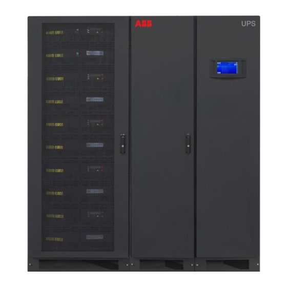
Page 23: Front View
Front View Figure 10: Front View of the Conceptpower DPA 500 Cabinet, Left Side with Closed Doors and Right Side with Open Doors and Dead Fronts Removed Active sub-modules Passive sub-modules System display Door handles Module-dedicated battery breakers (CB2-1, CB2-2, CB2-3, CB2-4, CB2-5) 250A / 600-800 VDC... -
Page 24: Connectivity
Figure 11 below represents the standard RS-232 interface cable used to connect an external computer to the UPS. Interface Cable (9-pin D-Sub male-to-female) (TXD) (RXD) (RXD) (TXD) (gnd) (gnd) Computer UPS JD1 9-pin D-Sub Figure 11: Connector cable – RS-232 Serial Port with 9-Pin D-Sub connection 24 Conceptpower DPA 500 480V UL │94-12-043275 A02... -
Page 25: User Interface And Dry Ports (Volt-Free Contacts)
Mains failure X2 / 1 Mains present X1 / 2 230Vac Interlock function (Ext manual EXT_MAN_BYP bypass) Max 230Vac / 2AT X1 / 1 Table 11: User Interface Board Conceptpower DPA 500 Conceptpower DPA 500 480V UL │94-12-043275 A02 25... -
Page 26: Usb Pc / Laptop Interface
JP 8 = ON External Output Breaker enabled JP 8 = OFF Parallel Board, PCB NW28140D or later versions: External Output Breaker disabled (default setting) JP1-JP2-JP3-JP4-JP5 = ON External Output Breaker enabled JP1-JP2-JP3-JP4-JP5 = OFF 26 Conceptpower DPA 500 480V UL │94-12-043275 A02... - Page 27 Multi-cabinet Configuration switch (see 5.1.6 and 6.1.2.4) 13 JD8 Parallel BUS connector For paralleling cabinets use optional adapter: Parallel BUS - Input Connector Parallel BUS - Output Connector Parallel Adapter JD 5 SW2-2 Figure 12: User Interface Board Conceptpower DPA 500 480V UL │94-12-043275 A02 27...
-
Page 28: Operation
Operation Commissioning The Conceptpower DPA 500 is a high quality electronic UPS that must be commissioned by a fully trained and certified field service engineer before being put into use. The commissioning of the UPS involves the connection of the UPS and battery, verifying the electrical installation and operating environment of the UPS, the controlled start-up and testing of the UPS, and customer training. -
Page 29: Installation Instructions
IMPORTANT: The BYPASS MODE (ECO-MODE) function of a parallel systems is the same as in single units of Conceptpower DPA 500. If in a parallel UPS system the load is transferred to the BYPASS (load on mains) and if the mains fail, all UPS’s will be automatically transferred to inverter within 5msec. -
Page 30: Dip Switch Sw1-9
DIP Switch SW1-9 The DIP Switch SW1-9 is located on every cabinet of Conceptpower DPA 500. With this switch it is possible to determine the “position of the cabinet” in a Multi-Cabinet Chain. Define each Conceptpower DPA 500 - Cabinet in a Multi-Cabinet Chain as: The “First”,... -
Page 31: On/Off - Main Buttons
Eco-Mode (Bypass Mode) in Parallel Systems The Eco-Mode function in a Parallel System is the same as in Single Systems. If in a Conceptpower DPA 500 Parallel System the load is supplied by the mains (load on mains) and in the event of mains failure, all UPSs will automatically transfer the load back to the inverters within 5msec. -
Page 32: Commissioning Of Multi-Cabinet Configuration
Check operational status and measurements Execute operational commands Monitor the power flow through the UPS system Check events and alarm history Silence alarms Adjust programmable parameters 32 Conceptpower DPA 500 480V UL │94-12-043275 A02... -
Page 33: Start-Up And Installation
The mimic diagram is the default screen. It shows the power flow through the UPS system (single cabinet as well as multi-cabinet configuration) and indicates its status. This diagram can be accessed from any screen using the corresponding icon in the display header. Conceptpower DPA 500 480V UL │94-12-043275 A02 33... -
Page 34: Module Selection Screen
The module selection screen will show the amount of module in the system show the status of each module as follows: • Black: module in operation • White: inactive module / switched off 34 Conceptpower DPA 500 480V UL │94-12-043275 A02... -
Page 35: Home Screen
Gives information regarding the identity of the UPS; User: Enables the adjustment of data such as date and time, automatic battery test, etc; Service: Enables the service technician to adjust several UPS parameters Conceptpower DPA 500 480V UL │94-12-043275 A02 35... - Page 36 Deep battery test Abort battery test Perform alarm test UPS Data This menu gives access to information regarding the manufacturing of the UPS. UPS Data Serial Number Manufacturing Firmware Version Hardware Version Display Version 36 Conceptpower DPA 500 480V UL │94-12-043275 A02...
-
Page 37: Operating Mode
7.4.7.1 Online Mode (Inverter Mode) The Online mode is the UPS operating mode in which the load is supplied through the rectifier and the inverter. Figure 20: Online Mode on Mimic Diagram Conceptpower DPA 500 480V UL │94-12-043275 A02 37... - Page 38 Eco Mode (Offline or Bypass Mode) In double conversion, the Conceptpower DPA 500 can achieve efficiency levels reaching up to 96%. To achieve higher efficiency levels, the UPS can be operated in Eco mode which increases the overall system efficiency up to 99%. In Eco mode, the load is supplied from the mains through the static bypass.
-
Page 39: Module Display - Control Panel
LED-indicator BATTERY is flashing. The LED-indicator ALARM is a visual indication of any internal or external alarm condition. At the same time an audible alarm will be activated. Conceptpower DPA 500 480V UL │94-12-043275 A02 39... -
Page 40: Buttons
NOTE: If a Cabinet is a Single Cabinet then it is seen as the “First” and “Last” in an imaginary Chain. So the positions of the DIP Switch SW1-9 must be set as shown below: 40 Conceptpower DPA 500 480V UL │94-12-043275 A02... -
Page 41: Status Screens
SET-UP USER Various settings can be performed by the user: Date/Time, automatic battery test, etc. SET-UP SERVICE SET-UP SERVICE Various adjustments can be performed by the service staff NO MORE MENU Conceptpower DPA 500 480V UL │94-12-043275 A02 41... -
Page 42: Event Log Screen
PERFORM BATT.TEST 3 Battery Test PERF. DEEP BATT.TEST PERF. DEEP BAT. TEST 4 Deep battery test ABORT BATT. TEST ABORT BATT. TEST 5 Abort battery test PERFORM ALARM TEST 42 Conceptpower DPA 500 480V UL │94-12-043275 A02... -
Page 43: Ups Data
End-Users PASSWORD. 2 Type in password Operating Modes Mode “On Line“ (Inverter Mode) 7.6.1 The ON-LINE-Mode is the UPS-Operating Mode in which the load is supplied through the RECTIFIER and INVERTER. Conceptpower DPA 500 480V UL │94-12-043275 A02 43... -
Page 44: Mode)
LCD-indication: “MANUAL BYP IS CLOSED” LED Indicators will indicate as shown in table below. Bypass-Switch Open – Normal operating condition (Load supplied by inverter) LCD-indication “MANUAL BYP IS OPEN” LED Indicators will indicate as shown in table below. 44 Conceptpower DPA 500 480V UL │94-12-043275 A02... -
Page 45: Output Switch/Parallel Isolator (Cb1)
UPS-Module 1 (bottom-most module in cabinet): Press both “ON/OFF” Main Buttons to switch on UPS. LCD panel must display: “LOAD DISCONNECTED PARALLEL SWITCH OPEN” and the LED-indicator will appear as shown below: Conceptpower DPA 500 480V UL │94-12-043275 A02 45... - Page 46 15. Check on LCD the Output Powers, Voltages Currents and Frequencies. 16. Load transfer to Inverter Go to Menu COMMANDS and choose command “LOAD TO INVERTER” and transfer the load to inverter on control panel of 46 Conceptpower DPA 500 480V UL │94-12-043275 A02...
-
Page 47: Shutdown Procedure
WARNING! The Conceptpower DPA 500 may be shutdown completely if the load does not need input power for an extended period of time. It may be switched to Maintenance Bypass Mode for service or maintenance purposes, or transferred to the OFF-LINE Mode (ECO-Mode), if the load does not need the highest degree of protection. -
Page 48: Load Transfer: From Inverter Operation To Maintenance Bypass
Configuration of UPS-System before starting the Transfer Procedure to Maintenance Bypass: The load is protected by Conceptpower DPA 500 and running in normal operation. (The UPS-Module is operating on inverter). Using LCD panel, select the COMMANDS menu and choose command “LOAD TO BYPASS” and transfer the load to mains. -
Page 49: Replacement Of Ups Modules
THE LOAD IS NOW SUPPLIED BY INVERTER POWER AND IS PROTECTED 7.11 Replacement of UPS Modules 7.11.1 Replacement of Single-Module UPS Systems If your Conceptpower DPA 500 consists of only one single UPS-Module, the UPS needs to be transferred to maintenance bypass. Note: Maintenance bypass is not included within the UPS cabinet. - Page 50 Check if the LEDs for LINE1 and BATTERYare green. If yes, mains voltage is OK; On the LCD: “LOAD OFF, SUPPLY FAILURE” will appear and the LED-indicator will indicate as shown below: 50 Conceptpower DPA 500 480V UL │94-12-043275 A02...
- Page 51 Open Maintenance Bypass (IA1) by turning it to position “OFF”. The load is now supplied by the static bypass. Transfer load to Inverter-Mode by means of COMMAND “LOAD TO INVERTER”. On LCD: “LOAD PROTECTED” will appear. THE LOAD IS NOW PROTECTED BY THE CONCEPTPOWER DPA 500. Conceptpower DPA 500 480V UL │94-12-043275 A02 51...
-
Page 52: Maintenance
12 months. Batteries contain dangerous substances that will harm the environment if thrown away. If you change the batteries yourself, call qualified organizations for battery disposal and recycling. 52 Conceptpower DPA 500 480V UL │94-12-043275 A02... -
Page 53: Troubleshooting
This alarm is only displayed if the UPS is on MANUAL BYP IS CLOSED by mains. Maintenance Bypass. Table 13: Troubleshooting In case of alarms not included in the list above, please contact the nearest authorized service center for assistance. Conceptpower DPA 500 480V UL │94-12-043275 A02 53... -
Page 54: Options
FACIULITY EPO MUST OPEN THE BYPASS PATH. The remote shutdown on terminal port X3/3.. X3/4 is located on the Conceptpower DPA 500 Cabinet. In order to allow removal, maintenance or testing of any remote shut down facility without disturbing the normal operation of the UPS, it is recommended that a terminal block, with linking facilities, be installed between the UPS and the stop button. -
Page 55: Wavemon Shutdown And Management Software
The UPS software will react automatically in such a case and shutdown the operating system. ABB has found thatit is important to have a complete solution for its UPS and is able to offer a wide range of monitoring/remote controls for assuring the maximum protection degree to the customers. - Page 56 - The real Battery autonomy time of the (whole) parallel system is computed continuously. - Maintenance on a redundant unit may be executed without annoyance to the management system (supervisor). 56 Conceptpower DPA 500 480V UL │94-12-043275 A02...
-
Page 57: Snmp Card/Adapter For Network Management / Remote Monitoring
Thanks to RCCMD it is possible to execute a shutdown in an heterogeneous multiplatform network. The new release RCCMD2 is an application available for all Operating Systems, analogous to PMC-Software. Our SNMP Interfaces are compatible to RCCMD. Conceptpower DPA 500 480V UL │94-12-043275 A02 57... -
Page 58: Technical Specifications
Accessibility: Front access only Unit Color: Powder coat, Midnight Black Wrinkle (Rohm & Haas #12-7001) Standards Safety UL 1778 5th edition, CSA C22.2 No. 107.3-14 Third Edition Electromagnetic Compatibility (EMC) IEC/EN 62040-2 Cat. 3 58 Conceptpower DPA 500 480V UL │94-12-043275 A02... -
Page 59: Input Characteristics
Note: in static bypass mode or eco-mode TN-C and TN-C-S can cause PE current to rise above 5% of phase currents. phases required neutral required Additional and Usual Information Connection: 4 wires, 3 phase + PE Conceptpower DPA 500 480V UL │94-12-043275 A02 59... -
Page 60: Output Characteristics
bypass / bypass inverter / in eco-mode <1 / <5 / <6 rated current fault clearing capability (bypass mode) for 20 ms 10xIn 10xIn overload current on bypass mode (< 25°C) continuously @ 110% load 60 Conceptpower DPA 500 480V UL │94-12-043275 A02... -
Page 61: Battery Characteristics
INVERTER to BYPASS and vice-versa. All other commands must be performed on the DPA display. With both displays in place (module and system level), the UPS offers full user friendliness without making compromises on robustness. Conceptpower DPA 500 480V UL │94-12-043275 A02 61... -
Page 62: Dpa Display
X1 is a 230VAC output which allows to interface with a interlock system. All X2 are potential free contacts and are rated: Max 250Vac/8A; 30Vdc/8A; 220Vdc/0.12A All X3 (except X3 5/6 which is a 12VDC source) are inputs, cable max. R 50Ω at 20mA 62 Conceptpower DPA 500 480V UL │94-12-043275 A02... -
Page 63: Options
User Interface Conceptpower DPA 500 11.7 Options • Maintenance bypass • SNMP cards • Battery Cabinet • Parallel KIT for paralleling multiple cabinets • Wooden box • Temp. sensor for battery temp. control Conceptpower DPA 500 480V UL │94-12-043275 A02 63... -
Page 64: On Request
Lb-In. 17.8 29.7 5/16 ALL INTERNAL BOLTS ARE SAE GRADE 5. NOTE BOLT HEAD MARKINGS ABOVE TO DISTINGUISH BETWEEN GRADES. ALL INTERNAL MACHINE SCREWS ARE GRADE 2. Table 14: Generic Torque Specification 64 Conceptpower DPA 500 480V UL │94-12-043275 A02... -
Page 65: Heat Dissipation
77953 97441 Airflow (25° - 30°C) with 100% non-lin. Load 1200 2400 3600 4800 6000 (acc. to IEC 62040-3) Heat Dissipation without load 1320 1980 2640 3300 Table 15: Heat Dissipation Specifications Conceptpower DPA 500 480V UL │94-12-043275 A02 65... -
Page 66: Warranty
12 Warranty http://www.tnbpowersolutions.com/terms_privacy for the latest warranty information. 66 Conceptpower DPA 500 480V UL │94-12-043275 A02... - Page 67 - in whole or in parts – is forbidden without prior written consent of ABB. www.tnbpowersolutions.com Copyright© 2015 ABB Thomas & Betts Power Solutions, LLC abb.com/ups All rights reserved 94-12-043275 Rev. A00-EN Conceptpower DPA 500 480V UL │94-12-043275 A02 67...