Siemens SIMATIC NET SCALANCE S615 Operating Instructions Manual
Industrial ethernet security
Hide thumbs
Also See for SIMATIC NET SCALANCE S615:
- Configuration manual (180 pages) ,
- Configuration manual (320 pages)
Table of Contents
SIMATIC NET
Industrial Ethernet Security
SCALANCE S615
Operating Instructions
08/2018
C79000-G8976-C389-04
___________________
Preface
___________________
Security recommendations
___________________
Description of the device
___________________
Installation
___________________
Connecting up
___________________
Dimension drawings
___________________
Technical specifications
___________________
Approvals
1
2
3
4
5
6
A
Table of Contents

Related Manuals for Siemens SIMATIC NET SCALANCE S615


Summary of Contents for Siemens SIMATIC NET SCALANCE S615
- Page 1 ___________________ Preface ___________________ Security recommendations ___________________ SIMATIC NET Description of the device ___________________ Installation Industrial Ethernet Security SCALANCE S615 ___________________ Connecting up ___________________ Dimension drawings Operating Instructions ___________________ Technical specifications ___________________ Approvals 08/2018 C79000-G8976-C389-04...
- Page 2 Note the following: WARNING Siemens products may only be used for the applications described in the catalog and in the relevant technical documentation. If products and components from other manufacturers are used, these must be recommended or approved by Siemens. Proper transport, storage, installation, assembly, commissioning, operation and maintenance are required to ensure that the products operate safely and without any problems.
-
Page 3: Preface
There, you will find among other things optical performance data of the communications partner that you require for the installation. The "SIMATIC NET Industrial Ethernet" system manual can be found on the Internet pages of Siemens Industry Online Support under the following entry ID: 27069465 (https://support.industry.siemens.com/cs/ww/en/view/27069465) ● "Passive network components" system manual This system manual contains installation instructions for several of the most common components and guidelines for setting up networked automation plants in buildings. - Page 4 ● Product CD / product DVD ● SIMATIC NET Manual Collection You will find the article numbers for the Siemens products of relevance here in the following catalogs: ● SIMATIC NET Industrial Communication / Industrial Identification, catalog IK PI ●...
- Page 5 Siemens’ products and solutions undergo continuous development to make them more secure. Siemens strongly recommends that product updates are applied as soon as they are available and that the latest product versions are used. Use of product versions that are no longer supported, and failure to apply the latest updates may increase customers’...
- Page 6 Explanations of many of the specialist terms used in this documentation can be found in the SIMATIC NET glossary. You will find the SIMATIC NET glossary on the Internet at the following address: 50305045 (https://support.industry.siemens.com/cs/ww/en/view/50305045) SCALANCE S615 Operating Instructions, 08/2018, C79000-G8976-C389-04...
-
Page 7: Table Of Contents
Table of contents Preface ..............................3 Security recommendations ........................9 Description of the device ........................15 Product characteristics......................15 Unpacking and checking ......................16 Accessories ..........................17 Terminals ..........................18 LED display ..........................20 SET button ..........................22 C-PLUG and KEY-PLUG ......................24 Installation ............................ - Page 8 Table of contents INSTALLATION........................58 EU declaration of conformity (*** TRANSLATION IN PROCESS! ***) ........59 A.2.1 ATEX ............................60 A.2.2 EMC directive (*** TRANSLATION IN PROCESS! ***) ............60 A.2.3 RoHS ............................61 (*** TRANSLATION IN PROCESS! ***) ................. 62 A.3.1 ATEX ............................
-
Page 9: Security Recommendations
● Keep the software up to date. Check regularly for security updates of the product. You will find information on this on the Internet pages "Industrial Security (https://www.siemens.com/industrialsecurity)". ● Inform yourself regularly about security advisories and bulletins published by Siemens ProductCERT (https://www.siemens.com/cert/en/cert-security-advisories.htm). ● Only activate protocols that you really require to use the device. - Page 10 Security recommendations ● Change all default passwords for users before you operate the device. ● Only use passwords with a high password strength. Avoid weak passwords for example password1, 123456789, abcdefgh. ● Make sure that all passwords are protected and inaccessible to unauthorized personnel. ●...
- Page 11 Security recommendations ● The following protocols provide secure alternatives: – SNMPv1/v2 → SNMPv3 Check whether use of SNMPv1 is necessary. SNMPv1 is classified as non-secure. Use the option of preventing write access. The product provides you with suitable setting options. If SNMP is enabled, change the community names.
- Page 12 Open Open Closed (when configured) NTP client UDP/123 Open Closed Closed (only outgoing) NTP server UDP/123 Open Closed Closed Siemens Remote TCP/443 Open Closed Closed Service (only outgoing) (cRSP/SRS) PROFINET UDP/34964 Open Open Open SCALANCE S615 Operating Instructions, 08/2018, C79000-G8976-C389-04...
- Page 13 Security recommendations Protocol Protocol/port Port status Default port status Authentication Encryption number Local access External access OpenVPN to TCP, UDP Open Closed Closed SINEMA RC depending (only outgoing) on server config [only with Key- Plug] TFTP UDP/69 Open Closed Closed (only outgoing) DynDNS TCP/80...
- Page 14 Security recommendations SCALANCE S615 Operating Instructions, 08/2018, C79000-G8976-C389-04...
-
Page 15: Description Of The Device
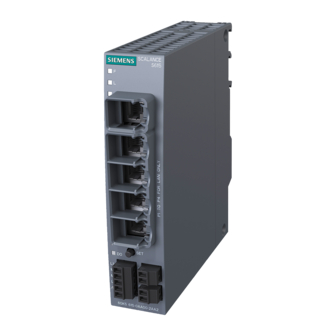
Description of the device Product characteristics Interfaces Functionality S615 Ethernet interface 5 x RJ-45 10 / 100 Mbps Digital input/output Scope of delivery The following components ship with the product: ● One device ● 1 x 5-terminal block for the power supply ●... -
Page 16: Unpacking And Checking
Description of the device 2.2 Unpacking and checking Unpacking and checking Unpacking and checking WARNING Do not use any parts that show evidence of damage If you use damaged parts, there is no guarantee that the device will function according to the specification. -
Page 17: Accessories
Description of the device 2.3 Accessories Accessories You will find further information on the accessories program for the S615 in the Industry Mall (https://mall.industry.siemens.com/mall/en/WW/Catalog/Products/10034139?tree=CatalogTr ee#). Type Properties Article number C-PLUG Exchangeable storage medium (32 MB) for the 6GK1900-0AB00 configuration data... -
Page 18: Terminals
Description of the device 2.4 Terminals Terminals The device has the following terminal strips. Connectors and terminal markings ① Terminal strip with five screw connectors Input for the power supply L1, M2, L2, M2 ② Functional ground ③ Terminal strip with two screw connectors Digital input +DI, -DI ④... - Page 19 Description of the device 2.4 Terminals ① ④ Terminals Wire end ferrule without plastic collar to DIN 0.2 mm 1.5 mm 46228/1 Wire end ferrule with plastic collar to DIN 0.2 mm 1.5 mm 46228/4 Stripped length 7 mm 7 mm See also Grounding (Page 41) SCALANCE S615...
-
Page 20: Led Display
Description of the device 2.5 LED display LED display Status Meaning No fault/error. The device is starting up or an error has occurred. Flashing The bootloader waits in this state for new firmware file that you can download by TFTP. Flashing Firmware on PLUG The device is performing a firmware update or downgrade. - Page 21 Description of the device 2.5 LED display Status Meaning Device turned off, no power supply. Device turned on, power supply present. No VPN connection is established. All configured VPN connections are established. Flashing Only some of the configured VPN connections are established. Ethernet connection to local computer or LAN not established Ethernet connection to local computer or LAN established Device receiving / sending data...
-
Page 22: Set Button
Description of the device 2.6 SET button SET button With a SCALANCE S615, the SET button is on the front of the housing. The SET button has the following functions: ● Restart Hold down the button for shorter than 3 seconds to run a restart. ●... - Page 23 Description of the device 2.6 SET button ● Reset to factory defaults – Hold down the button until the red fault LED (F) stops flashing after approximately 10 seconds and is permanently lit. – Now release the button and wait until the fault LED (F) goes off again. The device then starts automatically with the factory settings and can be reached via the IP address 192.168.1.1.
-
Page 24: C-Plug And Key-Plug
Description of the device 2.7 C-PLUG and KEY-PLUG C-PLUG and KEY-PLUG How it works The C-PLUG or KEY-PLUG is used to transfer the configuration of the old device to the new device when a device is replaced. NOTICE Do not remove or insert a C-PLUG / KEY-PLUG during operation! A PLUG may only be removed or inserted when the device is turned off. -
Page 25: Installation
Installation Safety notices for installation Safety notices When installing the device, keep to the safety notices listed below. WARNING If a device is operated in an ambient temperature of more than 50 °C, the temperature of the device housing may be higher than 70 °C. The device must therefore be installed so that it is only accessible to service personnel or users that are aware of the reason for restricted access and the required safety measures at an ambient temperature higher than 50 °C. - Page 26 Installation 3.1 Safety notices for installation General notes on use according to ATEX and IECEx WARNING To comply with EC Directive 2014/34 EU (ATEX114) or the conditions of IECEx, this enclosure or cabinet must meet the requirements of at least IP54 in compliance with EN 60529.
-
Page 27: Securing The Housing
Installation 3.2 Securing the housing Securing the housing Types of installation For the device, you have the following options: ● Wall mounting (no ceiling mounting) ● Installation on a DIN rail ● Installing on the S7-300 standard rail ● Installing on the S7-1500 standard rail ●... -
Page 28: Wall Mounting
Installation 3.3 Wall mounting Wall mounting Note The wall mounting must be capable of supporting four times the weight of the device, but at least 50 N. For information on the weight, refer to the section "Technical specifications (Page 53)". Installation 1. -
Page 29: Installing On The Din Rail
Installation 3.4 Installing on the DIN rail Installing on the DIN rail Installation ① 1. Place the third housing guide of the device on the top edge of the DIN rail ② 2. Press the device down against the DIN rail until the spring catch locks in place 3. -
Page 30: Installing On The S7-300 Standard Rail
Installation 3.5 Installing on the S7-300 standard rail Installing on the S7-300 standard rail Installation ① 1. Place the second housing guide of the device on the top edge of the standard rail ② 2. Press the device down against the standard rail until the spring catch locks in place 3. -
Page 31: Installing On The S7-1500 Standard Rail
Installation 3.6 Installing on the S7-1500 standard rail Installing on the S7-1500 standard rail Installation ① 1. Place the first housing guide of the device on the top edge of the standard rail ② 2. Using a screwdriver, pull down the catch on the rear of the device. -
Page 32: Installation In A 19" Mounting Frame
Installation 3.7 Installation in a 19" mounting frame Installation in a 19" mounting frame The 19" mounting frame is for installation of 2 SCALANCE S devices in a 19" rack. NOTICE Approvals Installation in a 19" mounting frame does not meet the requirements of the approvals: ATEX, IECEx, FM, UL and UL Haz-Loc. - Page 33 Installation 3.7 Installation in a 19" mounting frame 6. Connect the device to the local network, refer to the section "Ethernet port (Page 45)". 7. Connect the terminal with as short a cable as possible ≤ 150 mm and a large cross- sectional area of 1.5 mm²...
-
Page 34: Mounting On A Pedestal
Installation 3.8 Mounting on a pedestal Mounting on a pedestal Installation ① 1. Place the third housing guide of the device on the top edge of the pedestal ② 2. Press the device down against the pedestal until the spring catch locks in place 3. - Page 35 Installation 3.8 Mounting on a pedestal See also C-PLUG and KEY-PLUG (Page 24) SCALANCE S615 Operating Instructions, 08/2018, C79000-G8976-C389-04...
- Page 36 Installation 3.8 Mounting on a pedestal SCALANCE S615 Operating Instructions, 08/2018, C79000-G8976-C389-04...
-
Page 37: Connecting Up
Connecting up WARNING EXPLOSION HAZARD DO NOT OPEN WHEN ENERGIZED. Safety when connecting up Safety notices When connecting up the device, keep to the safety notices listed below. WARNING The equipment is designed for operation with Safety Extra-Low Voltage (SELV) by a Limited Power Source (LPS). - Page 38 Connecting up 4.1 Safety when connecting up Safety notices on use in hazardous areas General safety notices relating to protection against explosion WARNING EXPLOSION HAZARD DO NOT CONNECT OR DISCONNECT EQUIPMENT WHEN A FLAMMABLE OR COMBUSTIBLE ATMOSPHERE IS PRESENT. Safety notices for use according to ATEX and IECEx If you use the device under ATEX or IECEx conditions you must also keep to the following safety notices in addition to the general safety notices for protection against explosion: WARNING...
-
Page 39: Power Supply
Connecting up 4.2 Power supply Power supply The power supply is connected using a 5-pin terminal block. The power supply is non- floating. Signal Description 24 VDC Ground Ground 24 VDC Functional ground, refer to the section Grounding (Page 41)" SCALANCE S615 Operating Instructions, 08/2018, C79000-G8976-C389-04... - Page 40 Connecting up 4.2 Power supply External power supply Note Permitted external power supplies The power supply unit to supply the SCALANCE S615 must comply with the requirements for a limited power source according to IEC/EN 60950-1, section 2.5. The external power supply for the SCALANCE S615 must meet the requirements for NEC class 2 circuits as specified in the National Electrical Code ®...
-
Page 41: Grounding
Connecting up 4.3 Grounding Grounding EMC disturbances are diverted to ground via the functional ground. This increases the immunity of the data transmission. It is crucial for the correct operation of functional ground that the connection to the reference potential surface always has low impedance. Such a connection of the functional ground of the device does not go first through the cable channel and then to the mounting plate or DIN rail terminal, but goes directly to the mounting plate or DIN rail terminal. -
Page 42: Digital Input/Output
Connecting up 4.4 Digital input/output Digital input/output The digital input/output is a floating optical switch with which error/fault states can be signaled by breaking the contact. CAUTION Damage due to voltage being too high or too low The voltage at the digital input/output must not exceed 30 VDC and not fall below -30 VDC, otherwise the digital input/output will be destroyed. - Page 43 Connecting up 4.4 Digital input/output Digital input The 2-pin terminal block has the following assignment: 24 VDC DI- (input ground) If there is an adequate switching voltage at the digital input, the digital input is active and the "DI" LED is lit. SCALANCE S615 Operating Instructions, 08/2018, C79000-G8976-C389-04...
- Page 44 Connecting up 4.4 Digital input/output Digital output The 2-pin terminal block has the following assignment: Relay 24 VDC / 1 A Relay 24 VDC / 1 A SCALANCE S615 Operating Instructions, 08/2018, C79000-G8976-C389-04...
-
Page 45: Ethernet Port
Connecting up 4.5 Ethernet port Ethernet port The device has a certain number of ports to which the network nodes can be connected, e.g. a DSL router, a programmable controller, a machine with an Ethernet interface for remote monitoring or a PC. For the connection, use a path cable with an RJ-45 plug. -
Page 46: Replacing The Plug
Connecting up 4.6 Replacing the PLUG Replacing the PLUG NOTICE Do not remove or insert a C-PLUG / KEY-PLUG during operation! A PLUG may only be removed or inserted when the device is turned off. The device checks whether or not a PLUG is present at one second intervals. If it is detected that the PLUG was removed, there is a restart. - Page 47 Connecting up 4.6 Replacing the PLUG Removing the PLUG 1. Turn off the power to the device. 2. Insert a screwdriver between the front edge of the PLUG and the slot and release the PLUG. 3. Remove the PLUG. SCALANCE S615 Operating Instructions, 08/2018, C79000-G8976-C389-04...
- Page 48 Connecting up 4.6 Replacing the PLUG SCALANCE S615 Operating Instructions, 08/2018, C79000-G8976-C389-04...
-
Page 49: Dimension Drawings
Dimension drawings SCALANCE S615 Dimensions are specified in mm. Figure 5-1 Front view SCALANCE S615 Operating Instructions, 08/2018, C79000-G8976-C389-04... - Page 50 Dimension drawings 5.1 SCALANCE S615 Figure 5-2 Side view SCALANCE S615 Operating Instructions, 08/2018, C79000-G8976-C389-04...
-
Page 51: 19" Installation Frame
Dimension drawings 5.2 19" installation frame 19" installation frame Dimensions are specified in mm. Figure 5-3 Front view See also Installation in a 19" mounting frame (Page 32) SCALANCE S615 Operating Instructions, 08/2018, C79000-G8976-C389-04... - Page 52 Dimension drawings 5.2 19" installation frame SCALANCE S615 Operating Instructions, 08/2018, C79000-G8976-C389-04...
-
Page 53: Technical Specifications
Technical specifications SCALANCE S615 Article number 6GK5 615-0AA00-2AA2 Ethernet interface Attachment to Industrial Quantity Ethernet Design RJ-45 jack Characteristics: 10/100BASE-T • Ethernet IEEE 802 • 10/100 Mbps • Electrical data Power supply Input voltage 12 to 24 VDC min. 10.8 VDC, max. 28.8 V Maximum power con- sumption Digital input... - Page 54 To establish a VPN (Virtual Private Net- work), the following functions are available – Up to 20 connections – IPsec VPN, OpenVPN (as client) SINEMA RC client • Proxy server • Siemens Remote Service (SRS) • SCALANCE S615 Operating Instructions, 08/2018, C79000-G8976-C389-04...
- Page 55 Technical specifications SCALANCE S615 Monitoring / diagnostics / maintenance LEDs • Display of operating statuses via the LED dis- play. You will find further information on this in the operating instructions of the device. Logging • For monitoring have the events logged. SNMPv1/v2/v3 •...
- Page 56 Technical specifications SCALANCE S615 Operating Instructions, 08/2018, C79000-G8976-C389-04...
-
Page 57: Approvals
You can check which of the following approvals have been granted for your product by the markings on the type plate. Current approvals on the Internet You will find the current approvals for the product on the Internet pages of Siemens Industry Online Support at the following link: (https://support.industry.siemens.com/cs/ww/en/ps/15327/cert) -
Page 58: Installation
● "Industrial Ethernet / PROFINET Industrial Ethernet" System Manual (https://support.industry.siemens.com/cs/ww/en/view/27069465) ● "Industrial Ethernet / PROFINET - Passive Network Components" System Manual (https://support.industry.siemens.com/cs/ww/en/view/84922825) ● "EMC Installation Guidelines" configuration manual (https://support.industry.siemens.com/cs/ww/en/view/60612658) -
Page 59: Eu Declaration Of Conformity (*** Translation In Process! ***)
DE-76181 Karlsruhe Germany You will find the current EC declaration of conformity for these products on the Internet pages of Siemens Industry Online Support (https://support.industry.siemens.com/cs/ww/en/ps/15326/cert). The products described in these operating instructions meet the requirements of the following EC directives: ●... -
Page 60: Atex
Approvals A.2 EU declaration of conformity A.2.1 ATEX ATEX directive (correct usage in potentially explosive atmospheres) The product meets the requirements of the EU directive 2014/34/EU "Equipment and Protective Devices for Use in Potentially Explosive Atmospheres" according to the referenced standards to one of the following types of protection: Type of protection Applied standards ✓... -
Page 61: Rohs
Approvals A.2 EU declaration of conformity A.2.3 RoHS RoHS directive (restriction of the use of certain hazardous substances) The products described in these operating instructions meet the requirements of the EU directive 2011/65/EU for the restriction of the use of certain hazardous substances in electrical and electronic equipment: Applied standard: ●... -
Page 62: Translation In Process! ***)
Area". You will find this document • on the data medium that ships with some devices. • on the Internet pages under Siemens Industry Online Support (https://support.industry.siemens.com/cs/ww/en/). Enter the document identification number "C234" as the search term. The products described in these operating instructions meet the requirements of the EU directive 2014/34/EU "Equipment and Protective Devices for Use in Potentially Explosive... - Page 63 Approvals A.3 General approvals Permitted types of protection The following types of protection are possible: ● nA ATEX classification: II 3G Ex nA IIC T4 Gc Certificate no.: KEMA 07ATEX0145 X The products meet the requirements of the following standards: –...
-
Page 64: Iecex
Approvals A.3 General approvals A.3.2 IECEx IECEx The products described in these operating instructions meet the requirements of explosion protection according to IECEx. Note Type of protection of the device The devices are approved for various types of protection. You can find the type of protection of your device and the IECEx certificate number on the nameplate. -
Page 65: Fm Certification
Approvals A.3 General approvals A.3.4 FM certification Approved for use in Cl. 1, Div. 2, GP. A, B, C, D, T4 Cl. 1, Zone 2, GP. IIC T4 For temperature information "T.." or the maximum ambient temperature "Ta:..", refer to the type plate. -
Page 66: Ul Haz. Loc Certification (Explosion Protection)
Approvals A.3 General approvals A.3.6 UL HAZ. LOC certification (explosion protection) I.T.E. for HAZ.LOC. CL.I, DIV.2, GP A,B,C,D T4 CL.1, Zone2, GP IIC, T4 For temperature information "T.." or the maximum ambient temperature "Ta:..", refer to the type plate. Applied standards ●... -
Page 67: Index
Index S7-300 standard rail, 30 Wall, 28 Connecting up Digital input, 43 LED display, 20 Digital output, 44 Ethernet interface, 45 Grounding, 41 Power supply, 39 Power supply, 39 Product characteristics, 15 C-PLUG, 24 S7-1500 standard rail, 31 Digital input, 43 S7-300 standard rail, 30 Digital output, 44 Safety notices... - Page 68 Index SCALANCE S615 Operating Instructions, 08/2018, C79000-G8976-C389-04...