Yamaha EF3000iSE New Model Manual
Hide thumbs
Also See for EF3000iSE:
- Installation manual ,
- Service manual (327 pages) ,
- Owner's manual (148 pages)

Related Manuals for Yamaha EF3000iSE


Summary of Contents for Yamaha EF3000iSE
- Page 1 YAMAHA GENERATOR NEW MODEL GUIDE EF3000iSE EF3000iSEB YAMAHA MOTOR CO., LTD O.P.E. OPERATIONS SERVICE GROUP 318040 March 2003...
-
Page 2: Table Of Contents
CONTENTS INVERTER SYSTEM Benefits of an inverter generator EF3000iSE ........1 Multi-pole alternator features..............1 Control unit ...................2 Inverter system of EF3000iSE ..............2 Principles of power generation with an inverter generator....2 Function of control unit ................3 Electronic governor ................3 Function of electronic governor ............4 Throttle motor ..................4... - Page 3 With the adoption of the inverter system, it supplies high quality electricity equivalent to household power sup- ply. The EF3000iSE uses the same highly reputed and reliable MZ175 engine used on EF2600 for the USA and EF2300 for Europe. Air intake...
-
Page 4: Benefits Of An Inverter Generator Ef3000Ise
In addition, the EF3000iSE is packed full of convenient design features throughout, such as large fuel tank filling mouth, outstanding easy starting. The EF3000iSE is also a model that can be used for a wide range of applications, even able to supply sine wave AC current to a UPS, Uninterruptible Power Supply. -
Page 5: Control Unit
High temperature Control unit Inverter system of EF3000iSE In the EF3000iSE, the control unit and multi-pole alternator cooperate to generate AC output. The inverter, controlled by a 16-bit microcomputer, is a PWM sine wave inverter. * PWM: Pulse Width Modulation 1. -
Page 6: Electronic Governor
Power generation Stage 1. The rectifier circuit converts three-phase AC into DC and it maintains stable DC voltage using a con- stant voltage circuit Stage 2. The Constant voltage DC current is stored in a condenser. Stage 3. The PWM, pulse width modulator, inverter circuit generates a stable sine wave AC current. Stage 4. -
Page 7: Function Of Electronic Governor
Therefore, it also becomes possible to use low engine speed to meet a low electrical consumption. With the EF3000iSE, the control unit commands the throttle motor built into the carburetor to control the throttle valve, which gives it the ability to continuously... -
Page 8: Continuous Running Time
ON. Continuous running time EF3000iSE is able to run for 20.5 hours with 1/4 load with fuel tank full, when economy control switch is on. With rated load: 8.0 hours With 1/4 load: 20.5 hours... -
Page 9: Frequency Variation
Therefore, an inverter generator provides constant AC output frequency even if the load changes which is equivalent quality to the commercial power supplies. The frequency variation of EF3000iSE is less than 0.1 %. Voltage variation The output voltage with no load is approximately 10 %... -
Page 10: Electronic Breaker
It takes some duration to compensate the voltage from the momentary voltage drop by revving up the engine. This duration is called settling time. In case of an EF3000iSE, the settling time is shorter than 2 seconds, when a maximum rated load is turned on. -
Page 11: Control Panel
Control panel 120 V 60 Hz (USA) t r e 120 V 60 Hz (Canada) e o w q e ow q e o w q 230 V 50 Hz (Australia) 230 V 50 Hz (Europe) 1 Overload warning lamp 2 Output indicator lamp 3 Oil warning lamp 4 Choke knob... -
Page 12: Output Indicator
(green) will continue to be lit. Oil warning lamp As in previous Yamaha generators, the engine will shut off automatically when the oil level decreases to a specified level. When this happens and the recoil starter is pulled, the engine will not start and the oil warning light will turn... - Page 13 Cooling system The centrifugal fan equipped on the rotor performs forced air cooling of the system over the path listed below. Each part of the system is therefore continuously kept at a stable operating temperature with only a single fan. I Cooling air path I Control unit cover I Control unit...
-
Page 14: Dc 12 V Output
DC 12 V output DC output is provided on EF3000iSE exclusively for battery charging. Rated output: DC 12V - 12A (12 V - 8.3 A for Canada) 1 Main coil 2 Sub coil 3 DC coil 4 DC rectifier 5 Control unit... -
Page 15: Battery Charging
Battery charging I Conditions of use of the DC power supply (exclusively for charging 12V battery) The DC power supply is designed to charge a battery of 40AH which is half discharged. 12V battery The time taken to charge a battery depends on how the battery is discharged. Charging is complete when the specific gravity of the battery is 1.26-1.28. -
Page 16: Engine
I Handling precautions If you continue to charge the battery for many hours, the temperature of the electrolyte will rise and battery performance may deteriorate. Handling procedures vary with the type of battery. 1. Remove the cords and tubes from the battery and then remove the battery. 2. - Page 17 Introduction of Power Boost Technology EF3000iSEB is equipped with a DC-DC converter, which supplies supplemental electric current to the invert- er control unit to boost up the generator output for maximum 10 seconds. Control Unit DC-DC converter (Power Boost Technology) DC-DC converter is an electrical device to step up DC voltage.
- Page 18 * Overload indicator lamp : The DC-DC converter is turned on automatically, when the generator output exceeds over 180 % of its rated load to boost generator output to assist the starting cur- rent of the load, such as an air conditioner. When the DC-DC converter is turned on automatically, the generator is obviously overloaded, thus the overload indicator lamp blinks quickly with 0.5-second interval...
-
Page 19: Engine
MZ175 Engine Difference from EF2800i The intake port of the cylinder head is altered to improve engine performance. The push rod is altered to reduce operating noise of the engine. EF2800i (7VU) EF3000iSE (7WL) ID mark Steel Steel Aluminum Steel... -
Page 20: Ignition System
Ignition system Ignition coil & TCI TCI ignition system is equipped with a speed limiter function. Speed limiter: 4500 rpm The ignition coil and TCI unit is a single built-in unit, while the speed limiter unit is a separate component installed in the control box. -
Page 21: Auto De-Compressor System
Auto-decompression system This engine is equipped with auto-decompression sys- tem to facilitate engine starting operation. While the engine is stationary or running at very low speed, a pin provided in the camshaft is projected above the base circle of exhaust cam lobe. The pin, consequently, pushes valve lifter causing exhaust valve to stay open, thus the compression pres- sure is released. - Page 22 Transportation Please observe the following warnings when transporting the generator in a car, truck or other vehicle. Q WARNING: 9 Since there is the risk of fuel (gasoline) spilling from the fuel tank due to vibrations and impacts dur- ing transport, do not transport the generator with fuel in the fuel tank. 9 Since there is the risk of fuel (gasoline) vaporizing and igniting, do not allow the car or truck to stand for a long period of time in locations subject to direct sunlight with the generator inside the vehicle.
- Page 23 NOTE: The proper disposal of oil-based waste liquids is mandated by law (Pollution Control Ordinance). Please con- sult your Yamaha dealer. 1. Warm up the engine for a few minutes. 2. Turn the engine switch to the “STOP” position to stop the engine.
-
Page 24: Fuel Tank Removal
Fuel tank removal A #300 mesh filter is used that prevents debris, sand and other foreign objects from entering the fuel petcock and carburetor. Filter performance is enhanced, and overflow from the carburetor is prevented. Carburetor Fuel hose 2 A large-capacity fuel tank is used that has a capacity of 12.7 liters when filled to the red level. -
Page 25: Air Cleaner & Carburetor
Air cleaner Dual filter: Paper filter element and Semi-dry formed rubber element Air cleaner Foamed urethane filter Paper filter – 22 –... - Page 26 Muffler cleaning 1. Turn the engine switch to the “STOP” position to stop the engine. 2. Loosen the bolt and remove the muffler cap and muffler screen. 3. Remove the carbon deposits on the muffler cap the muffle screen and the spark arrester using a wire brush.
-
Page 27: Mf Battery
MF battery Size and Electrolyte Precautions and Electrolyte Filling Procedure Using the YTX12-BS (Yuasa) Battery Battery Size 12 V 10 AH (10 HR) Weight (when filled): Approx. 42 kg Electrolyte Precautions and Filling Procedure (Attached to the electrolyte container) YTX12-BS Electrolyte Please make sure to read this label and the attached Read WARNING:... - Page 28 I Handling Instructions Q WARNING: Please read the handling instructions provided with the battery before use to ensure proper use of the battery. Instructions at Start of Use 1. Requests Before Using 8 This battery is a sealed, non-spillable battery. Since performance following activation decreases, do not peel off the filler port seal (cap strip) that seals the battery filler ports until just before use.
- Page 29 I Initial Charging Procedure 1. Cases in which Charging of a New Battery is Required (Initial Charging) Although the Sealed Motorcycle MF Battery can be used after it is filled with electrolyte, it may not be able to start a cell motor in cases like those indicated in the table below. In such cases, perform initial charg- ing before using the battery.
-
Page 30: Special Tools
Special tools 1. Rotor assy holder A tool available in markets will serve. HOZAN C-349 (drum remover) overall length: 360 mm 2. Rotor assy puller You can remove the rotor ass’y using the flywheel magnet puller and M6 bolts (3). 90890-01351 Flywheel magnet puller 90890-01355 Bolt, flywheel magnet puller 3. -
Page 31: Wiring Diagram
TCI unit p Stepping motor G/Y R/W a Rectifier s Battery d Starter relay f Starter motor EF3000iSE (120V/60 Hz) 7WL2 010 1 Main coil 2 Sub coil 3 DC coil 4 DC rectifier 5 Control unit 6 AC pilot light... - Page 32 TCI unit p Stepping motor a AC switch s Rectifier d Battery f Starter relay g Starter motor EF3000iSE (120V/60 Hz) 7WL2 020 1 Main coil 2 Sub coil 3 DC coil 4 DC rectifier 5 Control unit 6 Noise filter...
- Page 33 TCI unit p Stepping motor G/Y R/W a Rectifier s Battery d Starter relay f Starter motor EF3000iSE (220V/50 Hz) 7WL3 010 1 Main coil 2 Sub coil 3 DC coil 4 DC rectifier 5 Control unit 6 AC pilot light...
-
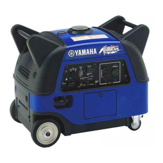
Page 34: External Views Of The Ef3000Ise
External views of the EF3000iSE Serial number Serial number – 31 –... -
Page 35: Specifications
Specifications Specifications EF3000iSE EF3000iSEB EF3000iSE EF3000iSE EF3000iSE EF3000iSE EF3000iSE Market CANADA CHINA GERMANY FRANCE AUSTRALIA Generator type 7WL2 010 7WL2 030 7WL2 020 7WL3 010 7WL3 020 7WL3 030 7WL3 040 Engine specifications Engine type MZ175 680 × 445 × 555... - Page 36 YAMAHA MOTOR CO., LTD. 2003-03 – 1.0 × 1...