Table of Contents
Quick Links
Table of Contents

Related Manuals for Siemens SIREC D200

Summary of Contents for Siemens SIREC D200
- Page 1 Manual Edition 12/2006 Display recorders SIREC D200 SIREC D300 SIREC D400 sirec...
-
Page 3: Table Of Contents
Electrical Installation ................... 13 Installation Category ....................13 Analogue Input Card ....................16 SIREC D200 Analogue Input (Standard) card ............19 Analogue Output Card.................... 21 Pulse Input Card..................... 22 Transmitter Power Supply Card ................24 Alarm Relay Cards & Digital Input/Output Cards..........24 Communications Connections ................ - Page 4 Section 4: Recorder Setup ................43 Power up .......................43 1. Menu Access......................43 2. Log On/Off ......................44 3. Local Settings ...................... 44 4. Time and Date Settings..................45 5. Firmware Options ....................45 Menu Path ....................... 45 Help ......................... 45 Main Menu ......................
- Page 5 The SIREC D Software Suite ................201 System Requirements .................... 202 Section 10: Spares List ...................203 SIREC D300 Recorder..................203 SIREC D400 Recorder..................207 SIREC D200 Recorder..................212 Section 11: Instrument Care and Maintenance ..........217 Cleaning Instructions ................. 217 Backlights ....................
- Page 6 Appendix A: Quality and Safety ..............231 CE Mark .....................231 Safety ......................231 Appendix B: Maths Expressions ..............233 Full Maths & Script Processing ..............233 Maths Credit Options .................... 233 Maths Variable and Function Tables..............234 Full Maths ......................241 Script Function Application Examples..............242 Maths Error Messages ..................
-
Page 7: Section 1: Preface
Thank you for choosing a recorder SIEMENS Thank you for purchasing the newest in our range of electronic data recording for SIEMENS SIREC D Advanced Graphic Recorders. The SIREC D300, SIREC D400 and SIREC D200 paperless chart recorders are the lat- est development of the solid-state replacement for traditional paper recorders. -
Page 8: Safety
Use” and UL 61010C-1 and CSA 22.2-1010.1, as options. If the equipment is used in a manner not specified, the protection provided by the equipment may be impaired. The SIEMENS range of instruments is compliant to the requirements for Class 1, Div.2 Haz- ardous (Classified) Locations. -
Page 9: Protocols Used In This Manual
Protocols used in this manual Protocols used in this manual Safety and Symbol Identification Table 1.3 : Symbol Description WARNING The WARNING symbol indicates a potentially hazardous situation, which, if not avoided, could result in death or serious injury. CAUTION This CAUTION symbol may indicates a potential- ly hazardous situation, which, if not avoided, may result in property damage. -
Page 10: Hazardous Voltage
Warnings and Safety Precautions 3. Repair is not to be attempted by a customer. Any adjustment or maintenance expected of an operator as part of the normal operation of the product is referred to as Opera- tional Maintenance. Any maintenance not expected of the operator is referred to as Corrective Maintenance and is to be carried out only by authorized service personnel or returned to an authorized repair centre. -
Page 11: Section 2: Installation
Contents Check that the contents and accessories are correct against the order or Model Selection Guide using the model number on the recorder. Contact SIEMENS immediately should there be any query. The contents are based on Unit Model Number ordered and will vary from unit to unit. The following list is provided as a general guide and not specific to any single unit. -
Page 12: Mechanical Installation
Mechanical Installation NOTICE The SIREC D200 recorder is an Emmisions Class A product. In a domestic environ- ment this product may cause radio interference in which case the user may be required to take adequate measures. Mechanical Installation Mounting and Viewing Angles Mounting - The SIREC D300, SIREC D400 and SIREC D200 recorders have an unlim- ited mounting angle. - Page 13 Cut-out Please note the recommended spacing for adjacent mounting SIREC D400 Figure 2.2 Panel cut-out The SIREC D300, SIREC D400 and SIREC D200 recorders are DIN Standard sizes and should be panel mounted. 43-TV-25-35 GLO Iss.4 Dec 06 UK A5E01001767-04...
- Page 14 Mechanical Installation SIREC D300 Dimension details 4 Mounting clamp positions. For standard units fit only two brackets on opposite sides of the unit, either top and bottom or left and right slots. NEMA 4X rated recorders require all four mounting brackets to be fitted. SIREC D300 Figure 2.3 Recorder dimensions...
-
Page 15: Installation Instructions
Mechanical Installation SIREC D400 Dimension details 4 Mounting clamp positions. For standard units fit only two brackets on opposite sides of the unit, either top and bottom or left and right slots. NEMA 4X rated re- corders require all four mounting brackets to be fitted. SIREC D400 Figure 2.4 recorder dimensions... - Page 16 Mechanical Installation SIREC D200 Dimension details 4 Mounting clamp positions. For standard units fit only two brackets on opposite sides of the unit, either top and bottom or left and right slots. NEMA 4X rated recorders require all four mounting brackets to be fitted.
- Page 17 Mechanical Installation Panel Mounting Clamp Installation The SIREC D300, SIREC D400 and the SIREC D200 recorders slide into the panel cut- out and are held in place by two (or four) panel clamps. The panel clamps should be fitted on diagonally opposite sides of the unit and tightened against the rear of the panel using two fixing screws.
- Page 18 Mechanical Installation Mounting Clamp Diagram Figure 2.1 SIREC D300 and SIREC D200 Mounting clamp 2 mounting clamp positions required on two opposite sides of the recorder. Nema 4X requires all 4 clamps to be fitted. Mounting clamp slots Figure 2.2 SIREC D400 Mounting clamp 4 mounting clamp positions (2 shown).
-
Page 19: Electrical Installation
If the fuse should blow again there is probably a problem elsewhere within the unit and the recorder should be returned for inspection to SIEMENS. Cables To fully comply with the requirements of the CE Mark, all cables connected to the rear of the unit should use screened cable terminated at both ends. - Page 20 D300 and Figure 2.4 on page 15 for the SIREC D400. The SIREC D200 the supply range is 24V DC +/- 10% (absolute limits are 20V to 30V DC). Also accepts 20 to 25V AC. Earth screw (ground) AC supply...
- Page 21 Analogue Output card E, F Pulse Input card A, B A, B, C, D, E, F Alarm Relay or Digital I/O card G, H, I “SIREC D200 Analogue Input (Standard) card” on page 19 43-TV-25-35 GLO Iss.4 Dec 06 UK A5E01001767-04...
-
Page 22: Analogue Input Card
Analogue Input card which is fitted in Slot A, see . SIREC D200 To fit this option card into the SIREC D200 recorder you will require an expansion card to interface to the recorder. 43-TV-25-35 GLO Iss.4 Dec 06 UK... - Page 23 Card Position Channel number 1 to 8 9 to 16 17 to 24 25 to 32 33 to 40 41 to 48 SIREC D200 Table 2.3 : Analogue Input cards Card 3 CH. 6 CH. 9 CH. 12 CH. 9-14...
- Page 24 9 to 14. The standard fit Analogue Input card is fitted in slot A with up to 6 channels (channels numbers 1 to 6). To fit this option card into the SIREC D200 recorder you will require an expansion card to interface to the recorder.
-
Page 25: Sirec D200 Analogue Input (Standard) Card
SIREC D200 Analogue Input (Standard) card The SIREC D200 is fitted with a standard Analogue Input card in Slot A, with up to 6 chan- nels. The card is also fitted with an Ethernet port as standard. Connection is made via 1 x 18-way screw terminal plugs that fit into a PCB header on the rear of the unit. - Page 26 Electrical Installation SIREC D200 Figure 2.8 Analogue Input card (std) - Slot A 1 2 3 4 5 6 7 8 9 10 11 12 13 14 15 16 17 18 CH.1 CH.2 CH.3 CH.4 CH.5 CH.6 WARNING HAZARDOUS VOLTAGES Insulation from channel to channel: Normally a channel can be safely connected to a hazardous voltage up to 150V AC common mode* with respect to earth.
-
Page 27: Analogue Output Card
(i.e. - inputs of all three channels connected to the same voltage). Failure to comply with these instructions may result in product damage Analogue Output Card Not available on the SIREC D200 recorder. connections are made via 1 x 12-way screw terminal plug that Analogue Output card fits into a PCB header on the rear of the unit. -
Page 28: Pulse Input Card
Figure 2.3 on page 14, Figure 2.4 on page 15 for the SIREC D400. The Pulse Input card is not available on the SIREC D200 the 8 Digital I/ recorder, however, O option card has 4 channels that can be set as pulse inputs (channels 1 to 4). The operat- ing frequency for pulse inputs on the Digital I/O card is 1kHz max. - Page 29 Electrical Installation WARNING HAZARDOUS VOLTAGES Insulation from channel to channel: Normally a channel can be safely connected to a hazardous voltage up to 300V AC common mode* with respect to earth. However, where a channel is connected to a safety low voltage circuit, an immediately adjacent channel must be adequately insulated from hazardous voltages between 150V AC and 300V AC max.
-
Page 30: Transmitter Power Supply Card
Figure 2.4 on page 15. The SIREC D200 has a 24V DC 130mA Transmitter Power Supply card that can be fitted as an option. Connection is made via a 2-way connector at the rear of the unit, the mating half is supplied with this option. - Page 31 Electrical Installation The SIREC D300 and the SIREC D200 recorders have only one slot available for digital inputs and relay outputs for either a 4 or 8 channel Alarm Relay card or an 8 or 16 channel Digital I/O card fitted in slot G, the position is identified on the rear panel. The 16 channel Digital I/O card is not available on the SIREC D200 recorders.
- Page 32 (Use C and NO) NO = Normally Open 8 and 16 Digital Input/Output Card The 16 channel Digital I/O card is not available on the SIREC D200 recorders. has 1A 24V DC rated relays that are connected via two 16- Digital Input/Output Card way connectors, the left connector for the first 8 channels and right connector for the second 8 channels.
- Page 33 Slot H 17 to 24 Slot H 17 to 32 Slot I 33 to 40 Slot I 33 to 48 The 16 channel Digital I/O card is not available on the SIREC D200. 43-TV-25-35 GLO Iss.4 Dec 06 UK A5E01001767-04...
-
Page 34: Communications Connections
The card also has connection for 24V DC Transmitter Power Supply, see “Transmitter Power Supply Card” on page 24. To fit this option card into the SIREC D200 recorder you will require an expansion card to interface to the recorder. See “SIREC D200 Expansion Card” on page 29. -
Page 35: Sirec D200 Expansion Card
NOTE: Once the recorder is powered up, if there are no active alarms associated with the “Fixed Relay”, the contacts will open. When the alarm is on they will close. SIREC D200 Expansion Card This is an interface card that is required when fitting the following option cards: •... - Page 36 Electrical Installation Keyboards All keyboards are native USB keyboards. Local keyboard layouts are not supported; all key- boards are recognised as US layout (QWERTY). Cordless keyboards and mice are not supported: • Dell Model # SK-8115 Keyboard • IBM ACC42 with USB hubs •...
-
Page 37: Section 3: Overview
SIREC D400 has a 12.1” Digital Colour LCD (TFT), SVGA Resolution (800 x 600 pixels) • SIREC D200 has a 5” Digital Colour LCD (TFT), QVGA Resolution (320 x 240 pixels) • Clear and intuitive operation, Industrial rugged Touch Screen with rapid navigation •... - Page 38 • Approvals - CE, CSA, UL. SIREC D300 and SIREC D400 also have FM approval. • NEMA 4X IP66 option. • Up to 50Hz (20 msec) Logging, 10Hz (100mS for SIREC D200. • Up to 16 Analogue Inputs for the SIREC D300 • Up to 48 Analogue Inputs for the SIREC D400 •...
-
Page 39: Recorder Functionality
• The SIREC D300 has up to 16 Analogue inputs, and the SIREC D400 has up to 48 Ana- logue inputs and the SIREC D200 has up to 12 Analogue inputs. 70Mb to 400MB of expandable non-volatile flash memory available plus additional removable storage media. -
Page 40: Features
• 5.5” Colour Active TFT for the SIREC D300 and 12.1” Colour Active TFT for the SIREC D400 and 5” Colour Active TFT for the SIREC D200 - with more than 256,000 colours makes it easy to interpret process data and take action with the intuitive bar charts, digital values, trends or customised displays. - Page 41 • The SIREC D300 and the SIREC D400 recorders have two USB host ports, one front and one at the rear. The SIREC D200 recorder has one front USB Host and another USB port available as an option at the rear. The USB ports can be used for attaching external USB devices such as a keyboard, mouse or a USB data storage key.
- Page 42 Ethernet (DHCP standard) communications port and Modbus RTU (slave mode) via an RS485 port. USB ports allow the use of an ASCII barcode reader. (RS485 port is an option for the SIREC D200 recorder). Email sent to your network connected PC triggered by an Alarm or an Event.
-
Page 43: Options - Hardware
• Pulse Frequency - four frequency inputs per board, are available to measure pulse signals up to 25 kHz (max. 2 cards). (Not available for the SIREC D200 recorder, but 4 pulse inputs can be used on the Digital I/O option card). - Page 44 Functions and Features SIREC D400 Standard Screens SIREC D400 recorder has up to 20 screens available for displaying combinations of charts, bars and DPMs can be configured, 4 examples below. Horizontal Chart, 8 Vertical Bars & 8 DPMS 16 Digital Panel Meters showing Max/Min values and Totals for each pen 16 Horizontal Bars...
- Page 45 Functions and Features SIREC D300 Standard Screens SIREC D300 recorder has up to 12 screens available fopr displaying combinations of charts, bars and DPMs can be configured, 6 examples below. Horizontal Chart and DPMs Horizontal Chart, 4 Vertical Bars and 4 DPMs 8 Digital Panel Meters 8 Horizontal Bars DPMs and Scales...
- Page 46 Functions and Features SIREC D200 Standard Screens SIREC D200 recorder has up to 10 screens available for displaying combinations of charts, scales and DPMs can be configured, 6 examples below. Horizontal Chart, 3 Vertical Bars Horizontal Chart and 6 DPMs...
- Page 47 Slot G Ethernet RS485 USB Host 100-250VAC Rear Panel AC power is connected via the standard configuration IEC chassis plug on the rear panel SIREC D200 Rear Connections Wire seal AC supply 100 - 250VAC Earth screw (ground) Analogue Input...
- Page 48 Functions and Features SIREC D400 Rear Connections AC supply Wire seal 100 - 250VAC Analogue Input / Pulse Input Earth screw Slot A (ground) Slot B Slot C 20 to 55VDC / Slot D 20 to 30VAC Analogue Input / 24/48V Instrument Pulse Input power (option)
-
Page 49: Section 4: Recorder Setup
Section 4: Recorder Setup Configuration of the recorder is performed in the Menu screens and the data is displayed in the Process screens. This section takes you through the Menu system and how to set up your recorder. See “Section 6: Screen Configuration” on page 155 for information on setting up screens to display the data. -
Page 50: Log On/Off
Power up 2. Log On/Off If Password (ESS - Extended Security System, 21CFR) security is active on your recorder a password is required to enter the menu system and process screens. Limited access is available without logging on. For ESS recorders only, locate the First Time Password System Setup sheet included in with your recorder or see “First Time’... -
Page 51: Time And Date Settings
Power up Default Time Zone Go from the Main Menu to Configure > Setup > Edit > General > Localisation > Time Zone The recorder is set to the default Time Zone for Eastern Time (US, Canada), (GMT -5.00). When the configuration is complete select the Finish button to Commit. 4. -
Page 52: Main Menu
Power up Main Menu Select a button to take you to the next menu • Configure - Configure the recorder through the Setup, Layout, Passwords and Settings See “Configure Menu” on page 47. menus. • Alarms - Acknowledge Alarms, Alarm configuration and their associated condition and See “Alarms Menu”... -
Page 53: Configure Menu
Power up Configure Menu (Main Menu > Configure >) The Configure screen gives access to the Setup, Layout, Password menus and Settings (Time and Date). The majority of the recorder configuration is done in the Setup menus. • Setup - In the Setup menu the user can configure how the recorder acquires, stores and actions data. -
Page 54: Setup Menu
There is another USB port at the rear of the recorder. The first USB device fitted will be USB1, therefore the second USB device fitted is USB2. Compact Flash not available SIREC D200 for the Load Setup (Main Menu > Configure > Setup > Layout) Setups can be loaded from Compact Flash or USB key. -
Page 55: Edit Setup
Power up Edit Setup (Main Menu > Configure > Setup > Edit Setup) Edit Setup will access the main configuration of the recorder through further sub-menus for: Field IO, Pens, Comms, Events/Counters, General, Screen and Recording set up. The Edit button may display a warning message if the Commit Later option has been select- ed This means changes to the configuration have been made but the changes have not been committed to the recorder. - Page 56 See “Ana- • Analogue Out - Select this to configure each Analogue Output channel. logue Out Menu” on page 55. SIREC D200 (Not available for the recorder). • Alarm/Digital IO - Select this to configure Relay Alarm Output card or Digital Input/Out- See “Alarm / Digital IO”...
- Page 57 1 to 8 8 Digital Input/Output 1 to 8 To fit the Analogue Input option card (Slot B) into the SIREC D200 recorder you will require an expansion card to interface to the recorder. See “SIREC D200 Analogue Input (Stan- dard) card”...
- Page 58 • Sample Rate - Select this for a list of available Analogue Input sample speeds. A Fast Scanning range of 50Hz (20ms) is available as a firmware option (not available for the SIREC D200 recorder) See “Firmware Credit System” on page 167.
- Page 59 Power up Figure 4.2 Effects of Damping and Rolling Average example Rolling Average of input signal (Pen 11) Input signal Damping on input signal (Pen 67) (Pen 10) Note: the Damping (Pen 10) has been offset for this example to be able to see the damping effect clearly •...
- Page 60 Figure 2.7, “Input signal wiring,” on ently for Active and Passive Burnout (see page 19 SIREC D200 recorder) ). (Active Burnout is not available for the Active burnout is an implementation of thermocouple health and provides error warning messages for a range of thermocouple activity/failure conditions. Passive burnout does not provide any error warning messages.
- Page 61 Active and Commit the change. Analogue Out Menu (Not available for the SIREC D200 recorder). (Main Menu > Configure > Setup > Edit Setup> Field IO > Analogue Out) Only available when an Analogue Out card is fitted as an option, 2 or 4 outputs are available per card.
- Page 62 • 8 Alarm Relay Output with 2 Digital Inputs 2 types of Digital IO cards • 8 Digital Inputs or Outputs (Not available for the SIREC D200 recorder). • 16 Digital Inputs or Outputs. Alarm Relay Card 4 Alarm relay output card or 8 Alarm relay Output with 2 Digital Inputs (6 fixed outputs and 2 configurable Digital Input or output) cards.
- Page 63 Power up For all cards select an Alarm/Digital # to display the configuration menu. Each Alarm/Digital has a list of menu items to be configured. • Enabled - Toggle On and Off • Digital Type - Set to Output Relay contact (Power) for the Alarm Relay cards. Toggle between Input and Output or Pulse Input for the Digital IO card.
- Page 64 Power up Pulse Input (Not available for the SIREC D200 recorder). (Main Menu > Configure > Setup > Edit Setup> Field IO > Pulse Input) Only available when a Pulse Input card is fitted as an option. The Pulse Input card operates up to a frequency of 25kHz max.
- Page 65 Power up Linearisation Tables (Main Menu > Configure > Setup > Edit Setup> Field I/O > Linearisation) Linearisation Tables - To be used with Analogue Input type Volts, Amps or Ohms. These are user defined tables that can be set up to allow a non-linear input signal to be dis- played on the recorder.
- Page 66 Power up Linearisation Table examples Figure 4.3 shows an example of a set of non linear signal inputs (X) and the required values in engineering units (Y) that have been entered into a linearisation table. They would pro- duce the following curve. Figure 4.3 Example of a 0-10V non-linear input signal (Eng.
- Page 67 Power up If the full input range is greater than the range used in the linearisation tables then the signal will carry on following the slope of the last two inputs. For example if we had a -50 to +50V range and just used the 0 to 10V linearisation table then the signal would look like Figure 4.4.
- Page 68 Power up Pens Menu (Main Menu > Configure > Setup > Edit Setup> Pens) Select the Pens button to display all the pens available. Menu path to current menu The Pens screen displays all the available pens. Each pen displays its scale settings.
- Page 69 Power up • Group - This pen can be allocated to a group of pens. Select this to display the list of available Pen Groups. If you select a group here this pen will be added to it. The group “Groups”...
- Page 70 Power up • Start Decade - Only available when the Scale Type is set to Log. Select and enter the start value of the first decade. • No. Decades - Only available when the Scale Type is set to Log. Select and enter the number of decades required.
- Page 71 Power up Fuzzy Logging has been developed as a secure data storage technique which has a self teaching data storage algorithm so the recorder stores data at a variable rate to match the process being monitored. Fuzzy Logging has intelligent resources to enable the most effective and efficient way of using the scan rate, storage capacity and record- See “Appendix F: Fuzzy Logging”...
- Page 72 Power up Alarms Menu (Main Menu > Configure > Setup > Edit Setup> Pens > Alarms) This is for setting up alarms on this pen only. Select the first available alarm eg. Alarm 1 and configure each alarm. Menu path to current menu The Pen Alarms screen displays up to alarm set points per pen.
- Page 73 • Relays Out - Select and choose which Relay Output(s) is triggered by this alarm (on this pen only). The Fixed button will use the common relay output on the power board SIREC D200 (24V relay). (Common relay output is not available for the recorder).
- Page 74 Power up Figure 4.5 Hysteresis Level 100% Alarm de-activated at this point 10% Hysteresis level Low Alarm Level Alarm activated at this point Totaliser Menu (Main Menu > Configure > Setup > Edit Setup> Pens > Totaliser) The Totals option must be active to use this option. See Table 7.1, “Firmware Options,”...
- Page 75 Power up • Type - Select this for a list of Types of totalising. Normal or Sterilisation. Normal totaliser function is usually associated with flow monitoring applications. Sterilisation* is where items are subjected to heat over a period of time. Each pen can be totalised according to the Fo or Po sterilisation* function at 250 °F (121.11°C).
- Page 76 Power up • Temp Input Units - For Sterilisation, select the temperature input units. • Start Temp - For Sterilisation, select the Start Temperature. • Ref. Temp - For Sterilisation, select the Reference Temperature. • Z Factor Temp - For Sterilisation, select the Z factor temperature •...
- Page 77 Power up Comms Menu (Main Menu > Configure > Setup > Edit Setup> Comms) Services Modbus, Web, Email, SNTP, FTP and Peers. See “Comms Services Menu” on page 73 TCP/IP (Main Menu > Configure > Setup > Edit Setup > Comms > TCP/IP) Transmission Control Protocol/Internet Protocol.
- Page 78 Power up • DNS/WINS/MDNS - Set to Automatic, click on this to activate and de-activate options. DNS = Domain Name System, WINS = Windows Internet Name Service, MDNS = Man- See “DNS/WINS/MDNS” on page 72 aged Data Network Services. • Ports - The Port numbers are associated with the IT system in use. Port numbers are set to a default but can be changed by the user to allow data traffic to use a specified See “Ports”...
- Page 79 Power up Network Admin (Main Menu > Configure > Setup > Edit Setup > Comms > Network Admin) This must be set up to ensure network printing can be performed, and emailing made easier, without being prompted for this information each time you want to print or email. This infor- mation will remain after a firmware upgrade.
- Page 80 Servers see Rear RS485 Port (A Comms option card and expansion card are required for the SIREC D200 recorder • RS485: 2 wire to support Modbus RTU. The RS485 connector plugs into the back of the recorder. This is a Master-Slave system where the recorders are slave devices.
- Page 81 Modbus can be used with RS485 or Ethernet ports. The Modbus protocol defines a mes- sage structure that controllers will recognise and use, regardless of the type of network over which they communicate. SIREC D200 recorder). (RS485 is an option for the • Enabled - Toggle On and Off •...
- Page 82 Power up Email (Main Menu > Configure > Setup > Edit Setup > Comms > Comms Services > Email) Set up this email menu in order to send emails for the following: “Alarms Menu” on page 66 1. When an Alarm is triggered, see Email Alarms in the 2.
- Page 83 Power up Password - Enter your password associated with your user name. If you have a system where the log in password expires and requires you to change it periodically, you will need to update the logon password in the recorders when you are forced to change your PC pass- word.
- Page 84 Power up • Period - Only available when Client Enable is active. Select and enter the time period in seconds required between checking and updating the time using the on-screen key- board. This will default to 120 seconds. • Threshold - Only available when Client Enable is active. This is a specified amount of time (in seconds) that the recorder clock must be within to ensure synchronisation with the network server.
- Page 85 Power up Peers The Peer services communication function sets up the recorder so it can be recognised on a network containing other X series recorders. This means that multiple recorders will be able to discover other recorders on the same local network in order to share data between them.
- Page 86 Power up NOTICE Remember that either Cause 1 OR Cause 2 will trigger Effect 1 AND Effect 2. Cause 1 and Effect 1 are not linked, just as Cause 2 and Effect 2 are not linked • An event can have two causes that triggers just one effect eg. A pen going into alarm and a Totaliser starts, this could have the effect of starting Logging.
- Page 87 Power up Figure 4.8 Event 1 example: Event 1 example: Adding Cause 1 Event 1 example: Adding Effect 1 Select which Pen number and which alarm on that pen, will have the alarm acknowledged. Event 1 example: Adding Effect 2 43-TV-25-35 GLO Iss.4 Dec 06 UK A5E01001767-04...
- Page 88 Power up Event Causes • Alarms - Set to cause an event when a pen goes Into Alarm, Out of Alarm or an Alarm is Acknowledged. Set the pen number and the Alarm that will trigger this event. • Totalisers - Set to cause an event when a totaliser Starts, Stops or is Reset. Select which pen has been set up as a totalise pen to trigger this event •...
- Page 89 Power up • Period - Only available when Interval is selected as a Sub Type. Set the time interval for how often this event should occur, eg. every hour would be 1h:00m:00s • Alignment - Only available when Interval is selected as a Sub Type. Select and enter a value from the list to align the scheduled event at specific intervals.
- Page 90 Power up An example of this could be: First setup your counter in the Counters menu. Enable it, Name it, enter the number the count will Start At and enter at what number it will Rollover and start again. See “Counters Menu”...
- Page 91 Power up Event Effects • Enabled - Tick to enable • Type – Choose from Mark on Chart, Logging, Totaliser, Digital Outputs, Alarm Ack, Email, Screen Change, Print Screen or Counters. • Mark on Chart - Is an effect if a pen goes into an alarm state a mark will be placed on a chart and will display, for example: “Pen 2 Alm 1: Into Alarm (37)”.
-
Page 92
Power up Table 4.4 : Adding Embedded Process Values Text Entry Function Examples [[name.v]] will embed the current recorder name <
> [[id.v]] will embed the current recorder ID <<21>> [[serial.v]] will embed the recorder serial number 200034 For example, in Mark on Chart enter: [[name.v]] [[P1.T]] is [[P1.V]] [[P1.U]] This will display the marker as: Furnace1 Temperature is 14.81 Deg C. - Page 93 Power up Event Effects (continued) • Logging - Is an event effect that can Start or Stop logging. Enter which one in Sub Type and select the relevant pen(s). • Totaliser - Is an event effect that can Start, Stop, Reset or Reset and Start a Totaliser. Enter which one in Sub Type and select the relevant pen(s).
- Page 94 Power up • Screen Change - Select this effect to change the screen when triggered by a cause. Eg. Pen 1 goes into Alarm and the screen changes from a chart to a DPM screen where Alarm markers are visible. •...
- Page 95 Power up • • Resume - this can be used after the chart has been stopped or paused. The chart data will continue from where it has been paused with no gaps displayed. But if the chart has been stopped the displayed data will display a gap in data until it is resumed •...
- Page 96 Power up General Menu (Main Menu > Configure > Setup > Edit Setup > General) From this screen select the buttons required for General recorder configuration. See “Ident” on • Ident - Unique recorder information; Name, Description and ID. page 90 •...
- Page 97 Power up Localisation (Main Menu > Configure > Setup > Edit Setup > General > Localisation) Set up the recorder for native language use and global settings including: • Language - Select native language menu prompts from list. • Help Language - Select native language for Help Files, currently English only availa- ble.
- Page 98 USB key or a Compact Flash card. The file type required to upgrade the Firmware has the file extension .xsu. Contact SIEMENS for more information. Insert the Compact Flash or USB key with the latest revision of Firmware (.xsu file format) and press the FW Upgrade button.
- Page 99 Power up Calibration (Configure > Setup > Edit Setup> General > Factory > Calibration) Cards will be calibrated in the factory. All ranges are factory calibrated and set to the default range of +/-12V. Table 4.6, “Calibration Input range table,” on page Date &...
- Page 100 Power up Table 4.5 : Analogue In Calibration Calibration Type Factory User Recalibrate Recalibrate All Factory All • The Calibration Positive Range box appears with instructions to connect the top limit of the input range. Once this is done press the Calibrate button. Next, the Calibration Neg- ative Range box appears instructing the user to apply the bottom range limit.
- Page 101 Power up Table 4.6 : Calibration Input range table Input Type Input Range Chrome Copel 50mV L Type TC 50mV M Type TC 50mV P (Platinel) 100mV D Type TC 50mV PT100 RTD 100mV PT200 RTD 250mV PT500 RTD 500mV PT1000 RTD 1000mV Nickel 100...
- Page 102 Power up In this menu there is a button for each slot for Cold Junction Calibration. Calibration is per- formed per slot/card. • Select the desired slot button. If a CJC connector is not fitted a message box will appear. •...
- Page 103 Power up Batch Menu (Configure > Setup > Edit Setup> General > Batch)) Batch is a firmware option which can be activated from “Credits” on page The Batch function allows the user to segment portions of data for further analysis. Setting up a batch requires information to identify and control batches of data.
- Page 104 Power up Printer Menu (Configure > Setup > Edit Setup> General > Printer) The Printer function is a firmware option that is selectable from the Factory menu > “Cred- its” on page 92. The screens that currently can be printed are all Status screens, Message lists, Process screens and Replay screens.
- Page 105 Power up Groups (Configure > Setup > Edit Setup> General > Groups) This menu is used for re-naming the groups.The same pen can only be associated in one group. To add a pen to a group see “Pens Menu” on page 62. You may want to create groups of pens in order to: •...
- Page 106 SIREC D300 55,000 hours (86,500 at 80% brightness) • • SIREC D400 43,000 hours for the(67,000 at 80% brightness) • • SIREC D200 40,000 hours (62,500 at 80% brightness) When the configuration is complete select the Finish button to Commit, Discard or Commit Later.
-
Page 107: Edit Recording
Set up Scheduled exports to transfer data at timed intervals, from internal flash memory to externally attached devices, Compact Flash or USB storage key. Compact Flash not avail- able SIREC D200 for the See “Recording Methodology” on page 120 “Storage Media Format” on page 120. - Page 108 USB2 is the second one fitted, front or rear of the recorder. Compact Flash not available SIREC D200 and the rear USB port is only available as an option for the Update Period - Select how often you wish data to be exported from the list provided; 10, 30 minutes, 1, 2, 12 or 24 hours.
- Page 109 Power up As you move the slider to the right, towards Chart, you will notice the allocated internal flash memory space for the chart data will increase in the bar above the slider. As you move the slider to the left, towards Log, you will notice an increase in the internal flash memory for the Log data in the bar above the slider.
-
Page 110: Layout
Power up Layout (Main Menu > Configure > Layout >) The user can configure how the data is presented on the screen. From the Layouts screen choose to Edit, Save or Load layouts in the recorder. Edit Layout (Main Menu > Configure > Layout > Edit) The Edit Layout menu displays a Screen button to enable and display Standard and Custom screens. - Page 111 Power up • • Charts, DPMs and Scales - Select which pen is displayed. Select and activate which scale is required to be displayed. • Showing (Pens) - Depending on the Template Type selected, choose Pens, Scales, Max/Min values or Totals, depending on what is set up to be displayed. Multiple Scales can be displayed by selecting more than one scale •...
- Page 112 Power up Appearance Chart background colour and graduations and the chart background colour when the record- er goes into an alarm state can all be changed. The same set of characteristics can be changed for a chart in Replay mode using the colour picker. The colour of the Time Stamp at the top of the chart and Marker (Mark on Chart) can also be changed.
- Page 113 There is another USB port at the rear of the recorder. The first USB device fitted will be USB1, therefore the second USB device fitted is USB2. Compact Flash not available SIREC D200 Load Layout (Main Menu > Configure > Layout > Load) Layouts can be loaded from Compact Flash or USB removable storage media.
-
Page 114: Passwords
Power up Passwords (Main Menu > Configure > Passwords >) The Password system manages the security within the recorder menu system. It allows re- stricted access within the recorder, providing password protection at different levels. If your recorder has ESS (Extended Security System) enabled the password system cannot be disabled. - Page 115 Power up Policy (Main Menu > Configure > Passwords > User Admin > Policy) At the top of the Policy menu are four levels to be assigned, these are the permission levels that will allow access to specific areas of the recorder menu system. The names of these levels can be edited here.
- Page 116 Power up • Pass Expiry - Set how many days before the current passwords will expire. (1 to 365 days and 0 will disable. For ESS recorders 1 to 180 days and no disable) • Expiry Warning - Set how many days before the passwords expiry date that a warning notice will appear.
-
Page 117: Settings
Power up Delete User (Main Menu > Configure > Passwords > User Admin > Delete User) This will list all the current users that have been entered into the password system. The Ad- ministrator can delete users from a drop down list. Note: Administrator cannot be deleted. -
Page 118: Alarms Menu
Power up Alarms Menu (Main Menu > Alarms >) Acknowledge and Configure Alarms by categories. Acknowledge Alarm (Main Menu > Alarms > Acknowledge Alarm) User acknowledgment of alarms can be performed at this menu, only Latched alarms can be acknowledged. Normal alarms cannot be acknowledged. When a Latched alarm is set up in the Pen, Alarms menu and a latched relay is configured, it will maintain its active state until the alarm has been acknowledged. -
Page 119: Screen Menu
“Edit Layout” on page 104 Edit Toolbar For Custom Screens SIREC D200 (Not available on the Select the Edit button whilst displaying a Custom Screen (Layout from Screen Designer) will take you to your current process screen and displays the Edit toolbar at the top of the screen. - Page 120 Power up To select a widget the Expert button must be disabled; displaying a red cross. A widget has green resize handles that appear when it is selected. To select an object the Expert button must be active, with no red cross showing. Objects have blue resize handles when selected. When a widget or object is selected it can be moved and resized.
- Page 121 Power up Select the pen number required. On a widget you can select the Parent, this will assign all the objects in the selected widget to the same pen. Select objects individually on the screen to assign different pens to each object within the widget. •...
- Page 122 Power up Parent Pens This does not apply to charts as charts normally have more than one pen displayed. The parent channel is the initial channel to be configured on a widget. All objects added to a wid- get (except charts and pen pointers) automatically default to using the parent channel. The parent itself allows the user to quickly make all of their objects update to use the pen number indicated by the parent.
-
Page 123: Batch Setup/Batch Control
Power up Batch Setup/Batch Control (Main Menu > Batch) Batch is a firmware option which can be activated from “Credits” on page The Batch function allows the user to segment portions of data for further analysis. Setting up a batch requires information to identify where the batch starts and stops. Batch data can also be paused, for viewing, and resumed. - Page 124 Power up This icon changes to show a batch is in progress Start Batch Mark on Chart Batch Mark on Chart A Batch marker will be placed on all process screens that have a chart displayed. The mark on chart will show where the batch is started with //S (Batch Name). The next time you press the Batch button the screen will have changed to give you the Batch Controls.
- Page 125 Power up When the batch is stopped the Batch Control screen reverts back to the Batch Setup screen so the user can start a new batch. “Batch Setup screens” on page 117. As well as a Mark on Chart for every command applied to the batch you can check the Mes- sages screen for details of the batch activity.
-
Page 126: Recording Menu
Compact Flash cards and USB keys can be done through your PC. The formatting types accepted by the recorder are FAT, FAT16 (2GB limit), TFAT and FAT32. Compact Flash not available SIREC D200 for the Start / Stop Recording The Recording screen will allow the user to manually Start and Stop recording. - Page 127 USB key into the port. After a few seconds the button becomes active. Compact Flash not available SIREC D200 for the USB1 is the first USB device to be fitted and USB2 is the second one fitted, front or rear of the recorder.
-
Page 128: Messages Menu
Power up Export “busy” light When data is about to be exported to a device the transfer busy light starts flashing. The flashing LED is a warning that the recorder is about to export to media. DO NOT remove the media whilst the LED is flashing. - Page 129 Power up Printing Screens All the Messages screens have a Print button, to execute this, the printer must first be con- figured in “Network Admin” on page 73 and in the “Printer Menu” on page 98. For de- tails on suitable printer types see “Print Support”...
- Page 130 Power up Message Format Table 4.7 : Message Types Icon Type Description Alarm Red Bell = in Alarm and not acknowledged Alarm Green Bell = out of alarm Green Bell / Black outline = out of alarm and Alarm acknowledged Alarm Green/Yellow bell = out Alarm not acknowledged Alarm...
-
Page 131: Process Menu
Power up Process Menu (Main Menu > Process) If Max/Min, Totals and Counters can be controlled from this screen. Controls for any process in use: • Max/Min - Reset Max/Min, Maximum or Minimum values by categories; • Totals - Start, Stop, Reset or View Totals by categories •... - Page 132 Power up Counters (Main Menu > Process > Counters) Select the Counters button to View and reset Counters. Counters have been split into the following types: • Alarm Counters – Reset will give you the option of resetting All alarms, by pen Groups or by individual Pens.
-
Page 133: Status Menu
Power up Status Menu (Main Menu > Status) Use the Status menus to easily check on the current configuration of the recorder. A number of status information screens are available to the user, these will provide information for re- porting and diagnostic purposes. The following Status screens are available •... - Page 134 Power up Printing Screens All the Status screens have a Print button, to execute this, the printer must first be configured “Network Admin” on page 73 and in the “Printer Menu” on page 98. For details on suitable printer types see “Print Support”...
- Page 135 (Note 1) Password CFR - (ESS - Extended Security System). This will only appear in the list if this feature is ena- bled in the recorder. It cannot be enabled by the firmware credit system - contact SIEMENS for details.
- Page 136 Power up IO Cards (Main Menu > Status > System > IO Cards) This will display the Slot position of each card in the recorder. The Card Type is identified as Analogue I/P, Alarm/Digital I/O, Analogue O/P or Pulse Input. The number of Channels on each card eg.
- Page 137 Power up Maintenance (Main Menu > Status > Maintenance) The recorder keeps track of important “life actions” for improved diagnostics and preventa- tive maintenance notification. The Maintenance button will become active when Health Watch/Maintenance is selected as a firmware option. To enable this go to “Options”...
- Page 138 Power up • Relay * cycle(s) - Displays the amount of relay cycles per relay listed. • Fixed - reports common relay output cycles Go Back to return to the previous screen or select Print to print the screen. Recording (Main Menu >...
- Page 139 Power up • Alarm Rate - Displays the alarm rate, in Hertz, if this has been set up to change when the pen goes into an active alarm state. A tick denotes if it is enabled and a star will indi- cate the current log rate •...
- Page 140 Power up Analogue In Status (Main Menu > Status > Diagnostics > Hardware > Analogue In) • Channel - Displays the Slot position eg. A, B, or C, D, E, F, the Analogue Input number and the system channel position. This will show a tick if this channel is enabled. See “Thermo- •...
- Page 141 Analogue Out Status (Main Menu > Status > Diagnostics > Hardware > Analogue Out)) Not available for the SIREC D200. • Channel - Displays the Slot position, eg. B, E or F, the Analogue Output number and the system channel position. This will show a tick if this channel is enabled.
- Page 142 Pulse Inputs Status (Main Menu > Status > Diagnostics > Hardware > Pulse Inputs) Not available for the SIREC D200. • Channel - Displays the Slot position, eg. A, B, C, D, E or F, the Pulse Input number and the system channel position.
- Page 143 Power up Comms Status (Main Menu > Status > Diagnostics > Comms) See “General Status” on page 137 • General - See “Modbus Status” on page 137 • Modbus - See “OPC Status” on page 138 • OPC - See “SMTP Status” on page 138 •...
- Page 144 Power up OPC Status (Main Menu > Status > Diagnostics > Comms > OPC) Status of the OPC activity • OPC Server Status - Tick will show the Server is running • OPCDA Min. Update Rate - Minimum Update Rate Supported for the OPCDAServer in milliseconds •...
- Page 145 Power up FTP Status (Main Menu > Status > Diagnostics > Comms > FTP) (File Transfer Protocol) - Displays the Type, Time, Date and Message details for FTP trans- fers Peers Status (Main Menu > Status > Diagnostics > Comms > Peers) Displays all recorders available on the network.
-
Page 146: Finish
Power up Finish When the Finish button is pressed at the end of a new set up or a change to a setup the following options are available. Commit This will save the new setup or changes to an existing setup, over-writing the existing one, and implement them into the recorder Field validation is performed when a change has been made, if a problem is identified, an error message is shown and the field in question clearly marked. -
Page 147: Section 5: Password Security
Section 5: Password Security Log On/Off If ESS (Extended Security System) Password security is active on your recorder a password is required to enter the menu system and process screens. Limited access is available with- out logging on, see Table 5.1 on page 145. When Log On is required the Log On button will appear in the top right of the Main Menu screen. - Page 148 Permissions Permissions may also be customised for an individual user, their permissions can be changed to become a customised user. However for global access restrictions, the user must be allocated a security level of Engineer, Supervisor, Technician or Operator, even though the individual permissions will differ.
-
Page 149: Password Policy
2. A box will appear and you will be prompted for your Administrator user name, which you have just created in items 1 to 7 listed above. 3. The Password dialog box will appear. The recorder enters a default password when a user is added so select “Yes”... -
Page 150: User Interface Requirements
User Interface requirements No Activity Timeout A “no activity” timeout programmable from 20 to 3600 seconds, which will automatically log out a user after a defined period of inactivity at the menu system or web page. Level Names The level names, such as Operator, Technician, Supervisor, Engineer are for internal refer- ence and are displayed as defaults, it is possible for the user to change the group names to suit their personnel structure. -
Page 151: Level Permissions
Level Permissions Table 5.1 : Default Level Permissions Default user levels of access to areas within the recorder menu system No Login Permission Area Admin Engineer Supervisor Technician Operator required Perm Area 1 Messages Perm Area 2 Screen Perm Area 3 Status Perm Area 4 View Totals... - Page 152 Table 5.1 : Default Level Permissions Default user levels of access to areas within the recorder menu system No Login Permission Area Admin Engineer Supervisor Technician Operator required Perm Area 22 Batch Setup Perm Area 23 Configure Settings Perm Area 24 Configure Layout Perm Area 25...
-
Page 153: Default Password Access
Default Password Access Default password access is set up within the recorder and can be changed by the Adminis- trator or the Administrator can assign another user to change the access permissions. Default permissions • Administrator Access is for the Administrator level only •... - Page 154 Figure 5.1 Default password access from the Main menu. Screen Menu - No Login Configure Menu - Operator Alarms Menu - No Login required. See Figure 5.7 Access. See Figure 5.2 required. See Figure 5.6 for Screen menu access. Configure menu access. for Alarms menu access (Permission Area 2) (Permission Area 13)
- Page 155 Figure 5.2 Default password access from the Configure menu Layout menu - Supervisor access. Setup menu - Technician access. All of the Layout menu buttons require Figure 5.3 for Setup menu Supervisor access. (Permission Area 24). access. (Permission Area 18) Edit Layout see Figure 5.7 Configure menu - Operator access...
- Page 156 Figure 5.3 Default Password access from the Setup Menu Setup menu - Technician access (Permission Area 18) Edit = Supervisor access Save = Technician access Load = Technician access Save and Load setup buttons require Technician access. (Permission Area 17) Edit menu - Supervisor access Figure 5.5 for Edit Setup...
- Page 157 Figure 5.5 Default password access from the Edit Menu Comms Menu - Engineering Access. See Figure 5.10 Field I/O Menu - Engineering Comms access. All of the Pens Menu - Access. All of the Field I/O Comms menu buttons require Supervisor Access.
- Page 158 Screen Edit/Edit layout - Supervisor access. All of the Edit functions in the status bar re- quire Supervisor access. (Custom Screens are not available for the SIREC D200). Screen menu - No Login required (Permission Area 2) Edit - Supervisor access...
- Page 159 Figure 5.8 Default password access from the Process Menu Process Menu - No Login required Max/Min - No Login Totals - No Login Counters - No Login Counters Menu - No Login required Reset button for all Counters re- quire Technician access (Permission Area 14) View requires No Login (Permission Area 7)
- Page 160 Figure 5.10 Default password access from the Comms Menu Comms Services - Engineering Comms Menu - Engineering access access (Permission Area 29) (Permission Area 29) Modbus - Permission Area 30 Services - Permission Area 29 Web - Permission Area 31 TCP/IP - Permission Area 33 Email - Permission Area 34 Network Admin - Permission Area 29...
-
Page 161: Section 6: Screen Configuration
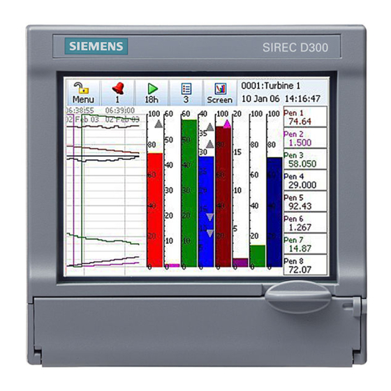
Section 6: Screen Configuration Process Screen Overview Figure 6.1 SIREC D300 Process Screen Standard Screen example - Chart and DPM Message Count menu allows quick access to Recording menu allows: Batch, User Mark on Chart, and Messages Detail • stop/start recording •... -
Page 162: Menu Bar
Menu Bar At the top of each process screen is the Menu bar. Recorder ID and Name alternates with the Screen Name. Date and Time Menu This gives direct access to the Menu System to set up the recorder. See “Section 4: Re- corder Setup”... -
Page 163: Screen Menu Bar
Screen The Screen button produces the Screen menu bar. Figure 6.2 Screen Menu bar Previous and Next buttons scroll back Press to print the current and forth through the screen list process screen Select to check or change the screen properties and set Layout Settings. -
Page 164: Replay
When using Custom Screens you can only replay 8 Pens on the SIREC D300 and 12 on the SIREC D400 recorder even though you can have more pens than this on the custom screen. SIREC D200 (Custom Screens are not available on the The Replay toolbar will appear at the bottom of the screen. - Page 165 • In – Zoom In on the chart being displayed. Place the chart cursor at the point you wish to zoom in to. Zooming In will magnify the chart to show greater detail around the cursor posi- tion. • Out – Zoom Out on the chart being displayed. Place the cursor at the point you wish to zoom out from.
- Page 166 long it will take to fill the memory, at the current chart speed, before the data will start to be recycled. See “Storage Bias” on page 102 How Replay works There are three separate “queues” of data, represented by the three different chart speeds. As you zoom in and out it switches between these different “queues”.
- Page 167 Figure 6.4 Zooming on a Replay screen 1 hour/div 12 hour/div replay chart replay chart (bigger divisions) 10 hour/div replay chart 10 mins/div replay chart 4 hour/div Zoom replay chart 5 mins/div Fast chart replay chart speed Zoom (600mm/hr) 2 mins/div 2 hour/div replay chart replay chart...
-
Page 168: Screen Menu Bar
Chart Speeds This is the speed at which the chart travels across the screen. There are three categories; Slow, Medium and Fast (default) chart speeds that can be set up in “Charts” on page 100. To change the chart speed gently tap the touch screen on a chart to activate the Settings button in the top right of the screen. - Page 169 Rate of Change Alarm Markers There are two types of rate of Change Alarms; Rate Up and Rate Down. They will appear on a DPM or Bar when a Rate Up or Rate Down type alarm has been set up in the “Alarms Menu”...
- Page 170 Batch stopped Pen out of alarm User Pen into alarm Totals started Figure 6.5 Mark on Chart Screen Markers Table 6.2, “Screen Markers,” on page 165 shows different types of markers that may appear on the screen during normal data activity and where they would appear. The markers change depending on if the signal goes High or Low, outside the Pen Scale, or outside the Input Range.
- Page 171 Trace at Min Screen Designer Screens (not available SIREC D200 on the Screen Designer screens, known as Layouts (file type .lay) can be created in the Screen Designer software on your PC and then loaded onto the recorder. This can be done via Compact Flash or USB transfer.
- Page 172 For layouts to be loaded into the recorder Custom Screens must be enabled as a Firmware option. See “Firmware Options” on page 168. It is recommended to save Screen Designer layouts directly from the software onto a Com- pact Flash or USB key. This will contain all the files required for loading the layout into the recorder.
-
Page 173: Section 7: Firmware Options
Section 7: Firmware Options Firmware Credit System The credits system is a flexible way of changing the recorder features without having to up- grade the firmware. Simply purchase a number of credits to cover your current and possibly future requirements and the recorder is delivered with the credits loaded. The credit value in each recorder is displayed in the Factory menu. -
Page 174: Firmware Options
4 extra pens to store and display totalised values, results of calculations, etc. Maximum is up to 16 extra pens for the SIREC D300, 12 extra pens for the SIREC D200 recorders, and 48 extra pens for the SIREC D400 recorder. -
Page 175: Remote Viewer
Firmware Credit System • Select Options to produce a list of Firmware options available with their credit values. The number or credits required is shown in brackets. • Toggle each option On or Off to enable the feature within the recorder. •... - Page 176 Firmware Credit System 43-TV-25-35 GLO Iss.4 Dec 06 UK A5E01001767-04...
-
Page 177: Section 8: Communication
• Web browser. Rear RS485 port For the SIREC D200 recorder a Comms option card is available with RS485 Modbus port and USB device connections. The card can be purchased and fitted at any time. The RS485 connection uses a 3-way connector. The card also has connection for 24V DC Transmitter Power Supply, see “Transmitter Power Supply Card”... -
Page 178: Protocols
USB communication ports can be found one at the front and one at the rear of the recorder. The SIREC D200 only has one USB port at the front fitted as standard. An extra rear USB port is only available with the Comms card option. -
Page 179: Hardware Installation
Hardware Installation Hardware Installation Device and PC Ethernet connections Connect an Ethernet cable from the Ethernet port on the back of the device to the Ethernet hub. Connect another Ethernet cable from the Ethernet port on the PC to the Ethernet hub. Hubs or Switches Hubs and Switches come in all different shapes and sizes. -
Page 180: Getting Connected - Ip Address
Hardware Installation Getting connected - IP Address Stand alone system This is for connecting a local device direct to a PC using an Ethernet crossover cable. By using a crossover cable, the PC is able to receive data transmitted from the device. Contact your IT systems administrator for setting up this link. -
Page 181: Local Area Network Setup
Hardware Installation Local Area Network setup This is a group of computers and/or associated devices e.g SIEMENS devices, that share a common communications line and typically share the resources of a single processor or server within a local geographical area (e.g. within an office). - Page 182 See “Commu- nications Server” on page 182. Compact flash is not available for the SIREC D200 recorder. Figure 8.3 Data Logging and Transfer Logged to Database SIREC D - Server 1...
-
Page 183: Comms And Sirec D Software
Internet for connectivity and transmission of data across heteroge- neous systems. With all SIEMENS software, performance improves with more RAM, faster CPUs, and faster and larger hard disk drives. NB. It is recommended that at least 100 Mbyte of free hard disk space is available for archiving data. -
Page 184: Software Installation
NB: This is an alpha/numeric code and must be entered exactly in upper case. Codes from other SIEMENS software will not work, each code is unique to the software supplied. The SIREC D - Software may find it necessary to automatically upgrade certain applica- tions within your PC to complete installation. -
Page 185: Start Up
Comms and SIREC D software Start Up The SIREC D - Software has been installed on the Hard drive of your computer in ‘pro- gram files’ unless during set up you have changed the destination folder. To re-start the software, click on ‘Start’, go to Programs and select SIREC D software, then select either SIREC - Server, SIREC - Manager or SIREC - Viewer according to which version of software has been installed. - Page 186 “Look up IP Address” button. The other method is to select the “Find Device” button. This will search for all SIREC D200, D300 and D400 recorders on the network using their Net- work ID, eg xs-nnnnnn (where “nnnnnn” is the recorder’s serial number).
- Page 187 Comms and SIREC D software If you select the “Recorder” button on SIREC - Server this will show a list of all recorders currently logged with a setup. The recorder just added will be the last one on the list. This name will be used to set up the Modbus Profile in Comms Server for the recorder.
-
Page 188: Communications Server
SIREC D - Server. The comms server manages the communications status of devices on a serial port (RS485) or through an Ethernet connection. Only Modbus protocol is available for SIREC D200, D300 and D400 devices, see “Modbus” on page 172. - Page 189 Communications Server The Comms Status shows all the activity of devices, Communications ports, Databases and Database Servers. The window to the left displays the areas controlled by the comms serv- er, the database servers and the communications ports. The display area(s) to the right will display details of any item selected in the left window.
- Page 190 Communications Server Comms ports is a list of ports available, . As de- Communication Ports COM1 COM8 Ethernet vices are added they are displayed under the port name. Click on Communication Ports to display a list of all the ports in the main window, tick the required port to enable. Click on a port and the main window splits into two windows, top and bottom.
- Page 191 Communications Server ed by going to Administration, Preferences and ticking the Show Diagnostics box, this will display properties and vales of a selected device. Add a Database To add a database to a server, right click on the server eg. Local Server, select Add Data- base and complete the dialog box details for the name and description of the device.
-
Page 192: Comms Server Setup
Communications Server Comms Server Setup Add a Device There are three ways to add a device, they all deliver the same dialog box: 1. Use the device icon in the top left of the comms server window. 2. Right click on a selected Comms port in the left window, COM1 to COM8 or Ethernet and select Add Device from the resulting menu. - Page 193 A Comms option card and expansion card are required for the SIREC D200 recorder. • IP Address - Go to Main Menu > Status > System > General. In this list is the recorder IP Address.
- Page 194 Communications Server Find Device This can be used to find SIREC D200, D300 and D400 recorders on the network. It uses the record- er’s unique Network ID to identify them and populate this list. Select your device from the list and press the Use Selection button to insert the recorder details into the Add Device box.
- Page 195 Communications Server Figure 8.6 New Device Status New device is added, ensure the “Active” box is ticked. The status lights will not be active yet. This is because no logging or graphs have been set up so no data is being requested. To set up Logging go to “Logging Configuration”...
- Page 196 Communications Server Comms Server Logging To set up logging you must first decide where to store the data. A database must be set up. The database can either be on the PC running Comms Server, or on another networked de- vice.
- Page 197 Communications Server The next section is Database Configuration, a list of connected database servers and a list of databases that are currently being logged to. In this section is a window showing the channels available to be logged. As channels are selected from this window, three additional buttons become active: ‘Add Channel selection’, select each channel for logging, ‘Add all Channels’...
- Page 198 Communications Server There is also a Database Events Logging box that can be ticked that allows any events to be logged to the database using Trendbus. (Not available for SIREC D200, D300 & D400 recorders). Summary of Logging Changes - If any changes are made using the Edit button, the Sum- mary of Changes button becomes active, this will show the last changes made to any of the channels for this configuration only.
- Page 199 Communications Server SIREC - • Select a chart control function for immediate effect on the recorder. Because Server is graphing the data that is being transferred in realtime the recorders running on SIREC - Server will not be affected. Comms Server Status Screen If you have a graph open Comms Server should be showing that the recorder is operating by displaying flashing green lights in the “Active column”.
- Page 200 Communications Server municated. See “OPC Interface - Open Process Control” on page 198. “OPC Cli- ents” on page 199 Database Logging This tab will display information on what is currently being logged to a database for the de- vice that is selected in the top window: its Destination or where the information is going to, Source or origin of the data (channel or event), Rate and Type of data sampling being com- municated.
- Page 201 Communications Server ed by going to Administration, Preferences and ticking the Show Diagnostics box, this will display properties and vales of a selected device. Add a Database To add a database to a server, right click on the server eg. Local Server, select Add Data- base and complete the dialog box details for the name and description of the device.
- Page 202 Communications Server Realtime Graphing To graph real-time data on SIREC - Server, press the “Real-time” button located on the left hand side. This will list all the recorders currently connected. The recorder set up on Modbus will be in the list. The recorder will be in the list under the name that you gave it when enter- ing the device details.
-
Page 203: Comms Database Server
Comms Database Server Comms Database Server This is the database icon which will appear in the bottom right of the screen to show that the SIREC D - Server software is running with the Database server active. Loads automatically with SIREC D - Server. Devices are held in databases and the databases are accessed via the Database Server. -
Page 204: Opc Interface - Open Process Control
OPC Interface - Open Process Control OPC Interface - Open Process Control “Credits” OPC Server connection must be enabled in the recorder by selecting the OPC option in on page 92. Many types of OPC Server software packages are available and are compat- ible with the recorders. -
Page 205: Web Browser
Web Browser OPC offers the following: • Combine different devices from different manufacturers in one system • Reduce installation time • Add devices without stopping existing software and systems • Quickly replace a device from one vendor with one from another •... -
Page 206: Internet Security Settings
Internet Security Settings Internet Security Settings Types of web browser for use with the Remote Viewer include Internet Explorer 5 and above. Figure 8.10, “Internet Security,” on page 200 shows an example from Internet Explorer ™ 6 on a Windows XP machine. -
Page 207: Section 9: Pc Software Suite
The Database Management Tool software is supplied with SIREC D Screen Designer Not available for the SIREC D200 recorder. SIREC D Screen Designer - is a separate software package that enables the user to design unique display layouts for transfer to the recorder’s screen. -
Page 208: System Requirements
SIREC D SIREC D200 SIREC Screen Designer software package is compatible with all D200 recorders. Layouts can be transferred on to single or multiple recorders of the same type, which SIREC D contributes to continuity and standardization of process data. For use with recorders only. -
Page 209: Section 10: Spares List
Section 10: Spares List SIREC D300 Recorder 43-TV-25-35 GLO Iss.4 Dec 06 UK A5E01001767-04... - Page 210 Ethernet USB host RS485 Common 24X TX Power Relay Supply Output Analogue Input or Pulse Input 20 to 55VDC/20 to 30VAC Input Instrument power CJC Sensor Analogue Input, Analogue Output Alarm/Digital IO RS485 43-TV-25-35 GLO Iss.4 Dec 06 UK A5E01001767-04...
- Page 211 Table 10.1 : SIREC D300 - Spares 51453012-502 D300 Processor Board Assy 51453006-501 D300 Analogue Input 4CH Assy 51453006-502 D300 Analogue Input 6CH Assy 51453006-503 D300 Analogue Input 8CH Assy 51453027-501 D300 Analogue Output 2CH Assy 51453027-502 D300 Analogue Output 4CH Assy 50001017-502 D300 Pulse Input 4CH Assy 51453009-501...
- Page 212 51452129-501 10 Ohm Resistors Pack of 8 Not shown 50001251-501 D300 Portable Case Not shown 51453051-501 D200, D300 and D400 Power cord Not shown (125V) SIREC D200 and D300 Portable Case Dimensions Height 165.1 (6.50) Width Depth 165.1 (6.50) (9.25) 43-TV-25-35 GLO Iss.4 Dec 06 UK...
-
Page 213: Sirec D400 Recorder
SIREC D400 Recorder 31 35 14 15 43-TV-25-35 GLO Iss.4 Dec 06 UK A5E01001767-04... - Page 214 33 39 Ethernet RS485 host 43-TV-25-35 GLO Iss.4 Dec 06 UK A5E01001767-04...
- Page 215 20 to 55V DC / 20 to 30VAC Input Common Relay Instrument supply Output Analogue Input or Analogue Output Sensor Analogue Input or Pulse Input Alarm / Digital IO 24V TX Power RS 485 Supply Output 43-TV-25-35 GLO Iss.4 Dec 06 UK A5E01001767-04...
- Page 216 Table 10.2 : SIREC D400 - Spares 51453012-501 D400 Processor Board Assy 51453006-501 D400 Analogue Input 4CH Assy 51453006-502 D400 Analogue Input 6CH Assy 51453006-503 D400 Analogue Input 8CH Assy 51453027-501 D400 Analogue Output 2CH Assy 51453027-502 D400 Analogue Output 4CH Assy 50001017-502 D400 Pulse Input 4CH Assy 51453024-501...
- Page 217 Table 10.2 : SIREC D400 - Spares 50004352-501 D400 12.1” Display 51453098-501 D400 Case and Back Plate 50004348-501 D400 Inverter and Cable kit 51453098-501 D400 Case and Back Plate Not shown 50005458-501 D400 Rear Terminal Cover kit Not shown 51453095-501 D400 Chassis kit 50000871-501 D400 Panel Gasket...
-
Page 218: Sirec D200 Recorder
SIREC D200 Recorder 43-TV-25-35 GLO Iss.4 Dec 06 UK A5E01001767-04... - Page 219 USB host Ethernet RS485 24V TX Power Supply AC supply 100 - 250VAC Wire seal Earth screw Analogue Input (ground) card Slot B (op- tion) 20 to 30VDC/ Alarm or 20 to 25VAC Input Digital I/O Instrument power Slot G (option) 24V TX Power Supply Output / Up to 6 Analogue...
- Page 220 Table 10.3 : SIREC D200 - Spares 50012923-501 D200 Processor Board/ 3 CH. Ana- Standard logue Input with Ethernet Assy 50012923-502 D200 Processor Board/ 6 CH. Ana- logue Input with Ethernet Assy 51453006-502 D200 Analogue Input 6CH Assy Requires Expansion...
- Page 221 51452129-501 10 Ohm Resistors Pack of 8 Not shown 50001251-501 D200 Portable Case Not shown 51453051-501 D200, D300 and D400 Power cord Not shown (125V) SIREC D200 and D300 Portable Case Dimensions Height 165.1 (6.50) Width Depth 165.1 (6.50) (9.25) 43-TV-25-35 GLO Iss.4 Dec 06 UK...
- Page 222 43-TV-25-35 GLO Iss.4 Dec 06 UK A5E01001767-04...
-
Page 223: Section 11: Instrument Care And Maintenance
• 43,000 hrs for the SIREC D400. Maximum luminosity 400 cd/m2, (67,000hr if used at 80%). • 40,000 hrs for the SIREC D200. Maximum luminosity 450 cd/m2, (62,500hr if used at 80%). For this recorder the backlight cannot be changed separately so the display has to be replaced. -
Page 224: Touch Screen
Touch Screen Touch Screen Care should be taken with the touch screen when handling the unit. Sharp and hard objects may pierce the touch screen and damage the display. Only use the stylus provided for screen selection. Clean the screen using a suitable touch screen cleaner. Abrasive materials will damage the touch screen. -
Page 225: Section 12: Technical Data & Specifications
• Frequency - 1 Hz to 25kHz, this will update once per second • Inputs - 4 x isolated inputs. A separate Pulse input card is not available for the SIREC D200 recorder, however the first 4 inputs on the Digital I/O card (option) can be used as pulse inputs. -
Page 226: Analogue Input
0.4V Relay Alarm/Digital Input Specification SIREC D300 and SIREC D200 recorders have one ‘slot’ for digital inputs and alarm relay outputs. All alarm card channels provide 240V AC isolation channel to channel and channel to recorder. Digital I/O channels will provide isolation to 100V AC test voltage (not for mains connection). -
Page 227: Digital Input Cards
(i.e. 16). SIREC D400 recorder will also provide at least one relay output for each analogue input (i.e. 48), there are three available slots for Digital inputs/ Relay Out- puts. Up to 8 relay outputs are available for the SIREC D200 recorder. Common Alarm Output (Not available for the SIREC D200 recorder) The common alarm output include a single alarm relay. - Page 228 Relay Alarm/Digital Input Specification 16 Digital Inputs (Not available for the SIREC D200 recorder) 16 Digital I/O card, this 16-channel card allows the user to configure each channel to be ei- ther relay output or digital input. Relay output rated at 24V DC 1 Amp rated (resistive load).
-
Page 229: Specification Tables
Specification Tables Specification Tables Specification Design Attributes Digital indicators and Display D300 Recorder Display size and Type: 5.5” diagonal, Digital Colour LCD (TFT) with Touch Screen Industrial grade with brightness adjustment and wide viewing angle Resolution: QVGA (320 x 240 pixels). Screen Saver: Set in minutes from 1 to 720, can be set to dim the screen or to switch off. - Page 230 Specification Tables Specification Design Attributes Data Storage Removable Media: Compact Flash card supports up to 4.0 Giga bytes. (Compact Flash is not avail- able as an option for the D200) Local Mass Storage Options: USB memory key - up to 2Gb, USB hard drive - up to 120Gb, Internal Data Buffer D300 and D400 Recorder: Non-volatile.
- Page 231 Specification Tables Specification Design Attributes Display Chart Speeds Chart rates: 1 mm/hour, 5 mm/hour, 10 mm/hour, 20 mm/hour, 30 mm/hour, 60 mm/hour, 120 mm/ hour, 600 mm/hour, 1200 mm/hour, 6000 mm/hour. Combinations of rates can be mixed and chart speeds can be set independently for each chart. Display speeds are independent of logging rate Messages Screen The message screen displays system information and records any setup activity that has been changed.
- Page 232 Specification Tables Specification Analogue Inputs Scales, Linear & Logarithmic Normal and Scientific notation Decimal Point automatic or programmable Engineering units, user definable (10 characters) Logarithmic: -38 min, to +38 max, (recommend up to 20 decades on one screen to ensure clarity) Input Isolation 300VAC channel-to-channel, channel-to-ground (Resistance thermometers are not isolated on the D200.
-
Page 233: Input Range Performance Accuracy Table
Specification Tables Input Range Performance Accuracy Table Analogue Input standard and expansion cards Input Actuation Temp. Input Range Accuracy (Linear) Stability +/- Impedance Millivolts DC -5 to 5, -10 to 10, +/- 0.2% F.S. 0.01%/ °C >10M ohms -25 to 25, -50 to 50, -100 to 100, +/- 0.1% F.S. - Page 234 Specification Tables Input Actuation Temp. Input Range Accuracy (Linear) Stability +/- Impedance 32 to 356 0 to 180 0.01%/ °C 356 to 3344 180 to 1840 3344 to 4515 1840 to 2490 11.7 α -328 to 1562 -200 to 850 0.01%/ °C PT100 = 0.00385...
- Page 235 Specification Tables Specification Options Email (optional) Setup email accounts to send the following: When an Alarm is triggered or an Email can be sent as a part of an Event occurring, such as: Alarms - In/Out/Ack , Totaliser – Start, Stop or Reset, Digital Inputs – On, Off or State change, TC Burnout –...
-
Page 236: Led Flash Codes
Specification Tables Specification Environmental and Operating Conditions Mechanical Shock Acceleration (g) Duration (ms) Mounting Position from Vertical Tilted Forward 5° 40° 40° Tilted Backward 5° 65° 65° Tilted to Side (+/-) 5° 65° 65° Power Requirements Mains Voltage (Vrms) 220 to 240 100 to 250 90 to 264 Low Voltage AC (Vrms) -
Page 237: Appendix A: Quality And Safety
Appendix A: Quality and Safety CE Mark SIEMENS recorders are compliant with Low Voltage Directive 73/23/EEC as amended by 93/68/EEC, and the Electromagnetic Capability Directive 89/336/EEC as amended by 92/ 31/EEC and 93/68/EEC. Safety The product range of instruments is compliant with the requirements of BS EN 61010- 1:2001 “Safety Requirements for Electrical Equipment for Measurement, Control and labo-... - Page 238 43-TV-25-35 GLO Iss.4 Dec 06 UK A5E01001767-04...
-
Page 239: Appendix B: Maths Expressions
Appendix B: Maths Expressions Full Maths & Script Processing The SIREC D200, D300 and D400 recorders are supplied with Basic Maths functions: Add, Subtract, Divide and Multiply. There are two further options that can be added, Full Maths and an extremely powerful Scripting processing module. Scripting delivers an additional level of enhanced capabilities with multi line script processing. -
Page 240: Maths Variable And Function Tables
Full Maths & Script Processing Scripting firmware credit option will allow the Full math functions plus the scripting func- tions in Table 14.3 on page 237, Table 14.4 on page 237, Table 14.5 on page 238, Table 14.6 on page 238 Table 14.7 on page 240. - Page 241 USB storage key fitted after the first USB has been fitted (front or rear). ** See Figure 22.1, “Comms variables,” on page 266. *Compact Flash is not available on the SIREC D200. Table 14.2 : Maths Function Table Maths Functions Syntax...
- Page 242 Full Maths & Script Processing Table 14.2 : Maths Function Table Maths Functions Syntax Description CosH* cosh[x] Returns the Hyperbolic COSINE of x Damp damp[x,y,z] x = input, y = Pen (pen variable being used) and z = damping limit in engineering units. See “Damping examples:”...
- Page 243 Full Maths & Script Processing Table 14.3 : Compare & Convert Syntax Description %RHc rhc[x,y] Returns % Relative Humidity with y as the dry bulb temperature in degrees C, and x the wet bulb tem- perature in degrees C %RHf rhf[x,y] Returns % Relative Humidity with y as the dry bulb temperature in degrees F, and x the wet bulb tem-...
- Page 244 Full Maths & Script Processing Table 14.5 : Accessors Syntax Description Ai[x] Get the value of Analogue Input number x Alamct Almct[x,y] Get the current alarm count for Pen x, Alarm y (the alarm number as identified in alarm mes- sages) Alamsl Almcl[x,y,z]...
- Page 245 Full Maths & Script Processing Table 14.6 : Boolean Operators Syntax Description Not equal to Returns a true or false result from testing if two variables are not equal to each other. e.g. IF (A1!=GLBV1) Returns a true or false result from testing if one or other or both tests are true.
- Page 246 Full Maths & Script Processing Functions for Scripts (Scripting is not available on the SIREC D200). Scripts evaluate at whatever the Analogue sample rate is set to. There is 500 character limit for scripting Table 14.7 : Functions for Scripts...
-
Page 247: Full Maths
Full Maths & Script Processing Full Maths Full Maths functions provides a simple and intuitive method for the user to carry out numer- ous mathematical functions. Some examples are shown below Table 14.8 : Full Maths examples Full Maths examples P4=lo[A1,A2] Pen 4 shows the result of the lowest of either A1 or A2... -
Page 248: Script Function Application Examples
Full Maths & Script Processing Script Function Application Examples (Scripting is not available on the SIREC D200). To enter a script for a Pen, ensure that “Maths Type” in the Pen Menu is set to Scripting. Example 1 4 flow meters are fed into the recorder to trend, totalise and record daily flow. The application requires that the user must know and record which flow meter is outputting the highest flow at any particular time. - Page 249 Full Maths & Script Processing GLBV1=3; If yes, then set display indicator to meter 3 return A3; And return the current flow reading else If none of the above are true, then 4 is biggest GLBV1=4; So set display indicator to meter 4 return A4;...
- Page 250 Full Maths & Script Processing if (A3>A2) Tests if A3 is bigger than A2 if(BLKV1==1) If it was then tests if A3 was bigger than A2 last time period return BLKV2; If it was return with the current change counter else If not then BLKV1=1;...
- Page 251 Full Maths & Script Processing BLKV1=trun[1,0]; If it is then keep the timer running without resetting return tget[1]; Return the current timer value else If not then BLKV1=tpause[1]; Pause the timer return tget[1]; Return the current (paused) timer value Note in this script above there is no way to reset the timer, this could be modified to allow the user to reset this timer from a switch fed into a digital input as follows: if(D1!=1) Tests if the DI 1 is not set...
-
Page 252: Maths Error Messages
Full Maths & Script Processing Example 4 Commenting in Scripts This is an example of how commenting can be used in scripts. you can use the standard C++ commenting, inline comments use \\ for example if ( A1 > 10 ) return 9;... -
Page 253: Appendix C: Thermocouple Connections
Appendix C: Thermocouple Connections How Thermocouples work Thermocouples produce a voltage dependant upon the temperature gradient between the hot and cold junctions. The hot junction is the measuring junction of the thermocouple, the cold junction is the point where the thermocouple wires are connected, usually the connec- tion block on the back of the recorder. -
Page 254: Thermocouple Cjc Compensation
Thermocouple CJC Compensation Thermocouple CJC Compensation The different methods for connecting thermocouples according to the type of reference are shown below. Internal Automatic Input terminals on rear panel of recorder Measuring junction Inputs Look-up table (Volts) added (converts (C+D) voltage read- ing to tem- perature) Thermocouple... -
Page 255: Ext 0°C Reference
Thermocouple CJC Compensation Ext 0°C Reference Thermocouple Copper wire cable Look-up table (converts volt- (Volts) age reading to ° 0 Volts temperature) Measuring junction Input Reference terminals junction held ° on rear Temperature reading at 0 to maths expression panel of recorder By keeping the reference junction at 0 °C then the negative input is act- Ext 0°C Reference. -
Page 256: External Input Reference
Thermocouple CJC Compensation External Input Reference Copper wire Normal signal processing Input Temperature terminals reading to maths on rear expression panel of Thermocouple recorder Table (convert R/T temp to Volts Reading in Volts Look-up table (Volts) Inputs (converts added PT100 voltage read- (C+D) ing to tem-... -
Page 257: Appendix D: Alarms
Appendix D: Alarms Alarms Menu (Main Menu > Alarms >) Acknowledge, Configure and View alarms from this menu. Acknowledging Alarms User acknowledgment of alarms can be performed at this menu, only latched alarms can be acknowledged. If a latched alarm is set up in the Pen, Alarms menu then a latched relay will maintain in its active state until the trigger source has returned to a no alarmed state and the alarm has been acknowledged. - Page 258 43-TV-25-35 GLO Iss.4 Dec 06 UK A5E01001767-04...
-
Page 259: Appendix E: Ethernet
Appendix E: Ethernet Ethernet Ethernet is a local area network (LAN) technology that transmits information between com- puters and other devices, at speeds of 10 or 100 million bits per second (Mbps). Each Ether- net equipped device operates independently of all other devices on the network. All devices attached to an Ethernet network are connected to a shared signalling system. -
Page 260: Email
Email General operation of the e-mail system The recorder sends messages for distribution by an e-mail server. The e-mail server is located by its IP address or it’s name as set-up in the communications set-up options. When the recorder sends an e-mail message, it locates the e-mail server and uses SMTP (Simple Message Transfer Protocol) to send the message to the e-mail server. -
Page 261: Appendix F: Fuzzy Logging
Appendix F: Fuzzy Logging What is Fuzzy Logging? is a real time Data Compression technique. Patent no. US 6,405,155 B2, Fuzzy Logging developed as an alternative to the more standard methods of recording data. Paperless Recorders are primarily used for exception recording. They spend most of their life trending and recording straight lines. - Page 262 Time Input Signal Continuously Sampled data: Fuzzy Logged data: 12 points only! Changing ‘slope’ requires more data points to be logged, to capture the shape correctly. Diagram 1 Points marked: are NOT logged, as they lie on an ‘imaginary’ straight line between points marked: The graph of the Fuzzy Logged data, looks identical to the graph of the sampled data, but has taken less than half the points to build it.
- Page 263 What about slowly drifting inputs? Again – No Problem. The algorithm is processed in ‘Real Time’, i.e. as the reading is taken. As it already knows the previous logged readings it can calculate where the next point should be (assuming it’s on a straight line) – if the measured value does not equal the pre- dicted value, the point is logged as it no longer forms part of the straight line.
- Page 264 It provides an excellent illustration of how less data points can be used to construct an iden- tical trace. Fuzzy Logged Sampled Logged Diagram 2. Note. This data extract was taken from a 56 hour temperature run, which resulted in approx- imately 1 Mbyte of sample data, and approximately 40 Kbyte of Fuzzy Logged data.
-
Page 265: Appendix G: F Sub Zero Sterilisation
Appendix G: F sub zero Sterilisation The significance of F The F value is used in the pharmaceutical and related industries in the sterilisation of items. A brief summary is included here to give the essence of the meaning of the terms used. When items are subjected to sterilisation by heating, the rate at which micro-organisms are killed is dependent on the temperature. - Page 266 Because of this small, but increasing contribution to F once T reaches 100 ºC, and the fact that in this trace the temperature exceeds 121.11ºC, the F value reaches 15 at time t = 20 minutes, at which point the sterilisation is complete, and cooling begins. For some applications it is allowed to report the F value that is finally achieved as the sample cools back to the start temperature, in this example 100 ºC, and so the...
-
Page 267: Appendix H: Calibration
Appendix H: Calibration AI Calibration and CJC Calibration For AI and CJC Factory and User Calibration see “Calibration” on page 93 Sensor Compensation Sensor Compensation may be required to improve accuracy on a sub range. This is an ad- justment to the value of the signal input on each channel, based on the Engineering units. To set this up in the recorder see Sensor Comp in the menu for “Analogue In Menu”... - Page 268 Sensor Compensation • Low Offset - enter an offset value that is offset against the Low Eng value. • High Eng - only active when Full Range is not active. Set the High limit for the Engineering units. • High Offset - enter an offset value that is offset against the High Eng value. Figure App H.21 Sensor Compensation Solid line shows without compensation and dotted line shows with compensation...
-
Page 269: Appendix I: Battery Data
Appendix I: Battery Data Location: Processor Board Located on the processor board this battery is used mainly for Clock battery back-up. Type 6032 CR2032 System Li/MnO /org.elyt. Voltage 3.0 V Cell Type Typical Capacity Weight (mAh) 6032 230 mAh 3 gms Approx Percent- age (%) of total weight... - Page 270 43-TV-25-35 GLO Iss.4 Dec 06 UK A5E01001767-04...
-
Page 271: Appendix J: Function Codes And Memory Maps
Appendix J: Function Codes and Memory Maps Modbus Memory Map Supplement: Start Address Address Description (Hex) (Hex) 1800 185F Analogue Input Value (48 inputs max.) 1880 18BF Communications Inputs (32 comms values max.)* 2400 247F Extended Comms Inputs (64 comms values max.)* 18C0 197F Pen Values (96 pens max.) -
Page 272: Analogue Input Value
Modbus Memory Map Supplement: Analogue Input Value Analogue readings in engineering units. 4byte IEEE floats using 2 Modbus registers per reading. Communications Input Values can be sent to the recorder for inclusion in the Maths Block, using command 16 up to 32 IEEE floats can be sent to the recorder. -
Page 273: Modbus Function Codes
Modbus Function Codes Modbus Function Codes 0004 can be used to send. Report Device ID: Slave ID for SIREC D200, D300 and D400 recorders is always 05. • Device description • Item Size in bytes Contents Device Description 16d, 0x10... - Page 274 Modbus Function Codes 43-TV-25-35 GLO Iss.4 Dec 06 UK A5E01001767-04...
-
Page 275: Index
Index Appendix B Maths Expressions ....233 Appendix C Thermocouple Connections . 247 Appendix D Alarms ..........251 AC Power ..............14 Appendix E Ethernet ......... 253 AI Calibration ............93 Appendix F Fuzzy Logging ......255 Factory Calibration ..........93 Appendix G F sub zero Sterilisation .. - Page 276 Card Positions and Channel numbers Comms Server ..50 ............182 Card and Slot Positions Add Pens for Logging ........... 191 ........15 Add a Database ..........185, 195 Change Log Speed, Alarms ......67 Add a Database Server ........185, 195 Change Passwords ..........111 Add a Device ............
- Page 277 Electrical Installation .........13 24V DC Input ............28 AC Power ..............14 Alarm Relay Card Connections ......24 DC Input 24V ............28 Analogue Input Card ..........16 DC Power ..............14 Analogue Output Card ..........21 DNS/WINS/MDNS ..........72 Cables ................13 Data Logging and Transfer ......175 Comms Connections ..........28 Data Storage, Overview DC Power...
- Page 278 F sub 0, Totaliser General Menu ...........68 ............90 F sub zero Sterilisation Appendix G Batch Menu .............. 97 ..259 Factory ..............91 ................78 Groups ............... 99 FTP Status ...............139 Ident ................90 Factory Calibration ..........93 Localisation .............. 91 Factory Menu ............91 Printer Menu ............
- Page 279 Jump feature Main Menu ............123 ...............46 Alarms Menu ............112 Batch Commands ........... 119 Batch Mark on Chart ..........118 Batch Setup/Control ..........117 Configure ..............47 Layout ..............104 Messages Menu ............122 Keyboards Passwords ..............30 ..............108 Process Menu ............125 Recording Menu ............120 Screen Menu ............
- Page 280 Message Format Remote Control Viewer .......... 35 ...........124 SIREC D200 Rear Connections ......41 Message List ............123 SIREC D200 Standard Screens ......40 Jump .................123 SIREC D300 Rear Connections ......41 Message Types ............122 SIREC D300 Standard Screens ......39 Alarms ..............122...
- Page 281 Diagnostics .............136 SIREC D200 Rear Connections Pulse Input Menu .....41 ..........58 SIREC D200 Standard Screens ......40 SIREC D200 and 300 Portable Case 206, 215 SIREC D300 Rear Connections .....41 SIREC D300 Standard Screens ......39 SIREC D400 Portable Case ......211 SIREC D400 Rear Connections .....42...
- Page 282 ..242 Spares List ............... 203 Scripts using commenting .......246 SIREC D200 ............212 Security Messages ..........122 SIREC D200 and D300 Portable Case ..206, 215 Security, Overview SIREC D300 ............203 ..........35 SIREC D400 ............207 Send Recorder Events ........183 SIREC D400 Portable Case .........
- Page 283 V,W,X,Y,Z TC Burn Out, Event Causes View Alarms ......82 ............112 TCP/IP Warnings and Precautions ................71 ........3 Web Browser DNS/WINS/MDNS ..........72 ............199 IP Address ..............71 Auto DNS ..............71 Ports ................72 Web Enable ...............75 Technical Data & Specifications ....219 xs-nnnnnn, Auto DNS ..........71 Analogue Output ............219...
- Page 284 43-TV-25-35 GLO Iss.4 Dec 06 UK A5E01001767-04...
- Page 286 Siemens Aktiengesellschaft @ 1 P A 5 E 0 1 0 0 0 1 7 6 7 @ Automation and Drives (A&D) A5E01001767 Sensors and Communication Process Sensors 76181 KARLSRUHE GERMANY A5E01001767-04 www.siemens.com/processinstrumentation...