Table of Contents
3-619-327-11(1)
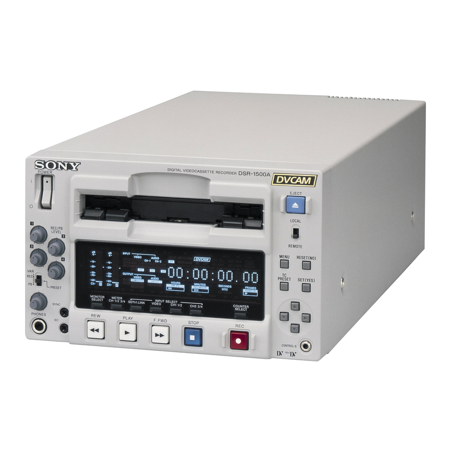
Digital
Videocassette
Recorder
Operating Instructions
Before operating the unit, please read this manual
thoroughly and retain it for future reference.
Note
The supplied CD-ROM includes operation manuals
for the DSR-1500A/1500AP Digital Video Cassette Recorder
(English, Japanese, French, German, Italian and Spanish versions).
For more details, see "Using the CD-ROM Manual" on page 13.
DSR-1500A/1500AP
© 2002 Sony Corporation
Table of Contents

Related Manuals for Sony DSR-1500A


Summary of Contents for Sony DSR-1500A
- Page 1 Note The supplied CD-ROM includes operation manuals for the DSR-1500A/1500AP Digital Video Cassette Recorder (English, Japanese, French, German, Italian and Spanish versions). For more details, see “Using the CD-ROM Manual” on page 13.
- Page 2 Owner’s Record The model and serial numbers are located at the bottom. Record these numbers in the spaces provided below. Refer to them whenever you call upon your Sony dealer regarding this product. Model No. Serial No. WARNING To prevent fire or shock hazard, do not expose the unit to rain or moisture.
- Page 3 Important Safety Instructions • Read these instructions. • Keep these instructions. • Heed all warnings. • Follow all instructions. • Do not use this apparatus near water. • Clean only with dry cloth. • Do not block any ventilation openings. Install in accordance with the manufacturer’s instructions.
- Page 4 AVERTISSEMENT Afin d’éviter tout risque d’incendie ou d’électrocution, ne pas exposer l’appareil à la pluie ou à l’humidité. Afin d’écarter tout risque d’électrocution, garder le coffret fermé. Ne confier l’entretien de l’appareil qu’à un personnel qualifié. CET APPAREIL DOIT ÊTRE RELIÉ À LA TERRE.
- Page 5 1. Für Ihren privat genutzten Videorecorder muß eine Fernseh-Rundfunk-Genehmigung beantragt werden, sofern nicht bereits eine Genehmigung für ein Fernsehgerät desselben Haushaltes vorliegt. Im geschäftlichen Bereich ist jeder einzelne Videorecorder anmelde- und gebührenpflichtig. (Auskunft ggf. bei der GEZ oder den Rundfunkanstalten.) 2.
- Page 6 Videograbadora digital ADVERTENCIA Para evitar el riesgo de incendios o electrocución, no exponga la unidad a la lluvia ni a la humedad. Para evitar descargas eléctricas, no abra el aparato. Solicite asistencia técnica únicamente a personal especializado. ESTE APARATO DEBE CONECTARSE A TIERRA. PRECAUCIÓN No se debe exponer la unidad a derrames ni goteos, ni se debe situar cerca objetos llenos de líquido, como por...
-
Page 7: Table Of Contents
Table of Contents Chapter 1 Overview Chapter 2 Recording and Playback Chapter 3 Convenient Functions for Editing Operation Features...9 DVCAM Format ... 9 Variety of Interfaces... 10 Compact Size ... 10 Facilities for High-Efficiency Editing... 10 Other Features ... 11 Optional Accessories... - Page 8 Chapter 4 Menu Settings Chapter 5 Connections and Settings Chapter 6 Maintenance and Troubleshooting Appendixes Table of Contents Digitally Dubbing Signals in DVCAM/DV Format...59 Menu Organization ...63 Menu Contents...66 Setup Menu ... 66 Auto Mode (AUTO FUNCTION) Execution Menu... 79 Changing Menu Settings ...80 Buttons Used to Change Settings...
-
Page 9: Features
The following are the principal features of the unit. DVCAM Format DVCAM is a professional -inch digital recording format developed by Sony from the consumer DV component digital format. Overview Chapter High picture quality and high stability... -
Page 10: Variety Of Interfaces
DSBK-1501 board, SDTI (QSDI)-format video, audio and time code signals can be transferred between the unit and the Sony EditStation at normal speed. When this unit is connected to another DVCAM VCR, it is possible to copy compressed signals between the two VCRs. -
Page 11: Other Features
Video process control For analog video output and SDI-format video output, you can use menu items to adjust the video output level, chroma signal output level, setup level (for DSR-1500A), black level (for DSR-1500AP), and chroma phase. Reference signal connection... - Page 12 The analog video signals that can be input are as follows. • Composite video signals • S-video signals • Component video signals (Y, R Y and B Y) Features...
-
Page 13: Using The Cd-Rom Manual
Using the CD-ROM Manual The supplied CD-ROM includes operation manuals for the DSR-1500A/1500AP Digital Video Cassette Recorder (English, Japanese, French, German, Italian and Spanish versions). CD-ROM System Requirements The following are required to access the supplied CDROM disc. • Computer: PC with MMX Pentium 166 MHz or faster CPU, or Macintosh computer with PowerPC CPU. -
Page 14: Location And Function Of Parts
Location and Function of Parts Front Panel a POWER switch b Audio level meters c PHONES connector and control knob d SC control e SYNC control A Audio input/output level control section (see page 16) B Video/audio input setting section (see page 17) Location and Function of Parts f Cassette compartment POWER... - Page 15 a POWER switch Press the “ ” side to power on the unit. This causes the audio level meters and the display section to light. To power off the unit, press the “ ” side of the switch. b Audio level meters These two meters indicate the recording audio levels during recording or EE mode* and the playback audio levels during playback.
- Page 16 When CH-3/4 mode is selected with the METER CH-1/ 2 3/4 button: Audio level meters PHONES connector CH-3 (channel 3) only. Channel 3 only Only the left meter lights. (monaural) CH-4 (channel 4) only. Channel 4 only Only the right meter (monaural) lights.
- Page 17 B Video/audio input setting section INPUT SELECT SDTI/i.LINK VIDEO CH1 1/2 CH2 3/4 c CH1 1/2 button b VIDEO button a SDTI/i.LINK button a SDTI/i.LINK (SDTI (QSDI) interface/i.LINK selection) button Each press of this button cycles through the following input signal selection options. •...
- Page 18 is possible to adjust the audio levels on the two channels separately. You can switch the audio recording mode with the REC MODE menu item (see page 73). The selection is indicated by the REC MODE display on the front panel. Location and Function of Parts...
-
Page 19: Display Section
C Display section INPUT VIDEO V:SDTI COMPOSITE CH-1 1/2 SDTI S VIDEO ANALOG i.LINK Y-R,B AES/EBU SDI SG SDI SG OUTPUT VIDEO COMPOSITE SDTI S VIDEO Y-R,B b OUTPUT signal display section a INPUT signal display section U-BIT SERVO COUNTER HOURS PB F 48K 44.1K 32K... - Page 20 Composite signal • When S VIDEO is selected: Connectors Output signals Y/CPST Y signal R Y/C/CPST C signal (3.58 MHz for DSR-1500A/ 4.43 MHz for DSR-1500AP) B Y/CPST (SUPER) Composite signal • When Y R,B is selected: – Connectors Output signals...
- Page 21 COUNTER: Count value of the time counter U-BIT: User bit data TC: SMPTE time code (for DSR-1500A) or EBU time code (for DSR-1500AP) e SERVO (servolock) indicator Lights when the drum servo and capstan servo are locked.*...
-
Page 22: Tape Transport Control Section
32K indicator: Lights during playback of a tape recorded in 4-channel mode (32 kHz). o REC MODE (audio recording mode) display This indicates the audio recording mode currently selected with the REC MODE menu item (see page 73). 2CH indicator: Lights in 2-channel mode (48 kHz). 4CH indicator: Lights in 4-channel mode (32 kHz). - Page 23 E Menu control section a MENU button b RESET (NO) button MENU RESET(NO) c TC PRESET button SET(YES) PRESET d SET (YES) button e fFgG buttons a MENU button Press this button to display the menu on the monitor screen and the time counter display.
-
Page 24: Rear Panel
Rear Panel VIDEO Y/CPST REF.VIDEO d REF. VIDEO IN connectors a AC IN connector Use the supplied power cord to connect this to an AC outlet. DV IN/OUT connector (6-pin IEEE-1394) This connector inputs and outputs digital video and audio signals in DV format. - Page 25 75 When S VIDEO is selected: Connectors Input signals Y/CPST Y signal R Y/C C signal (3.58 MHz for DSR-1500A/ 4.43 MHz for DSR-1500AP) — (not usable) AC IN AUDIO IN R-Y/C When Y R,B is selected: –...
- Page 26 Connectors Output signals Y/CPST Y signal R Y/C/CPST C signal (3.58 MHz for DSR-1500A/ 4.43 MHz for DSR-1500AP) B Y/CPST Composite signal (SUPER) When the CHARA. DISPLAY menu item (see page 68) is set to ON (factory default setting), the B Y/ CPST (SUPER) connector outputs a composite video signal with superimposed text information.
- Page 27 C Digital signal input/output section (optional DSBK-1501 Digital Input/Output Board) The connectors in this section are available when the optional DSBK-1501 board is installed. a SDI/SDTI (QSDI) IN connector OUT1 a SDI/SDTI (QSDI) IN (Serial Digital Interface/ Serial Data Transport Interface (QSDI) input) connector (BNC type) This connector inputs digital video and audio signals in SDTI (QSDI) or SDI format.
- Page 28 Location and Function of Parts...
-
Page 29: Usable Cassettes
Recording and Playback Usable Cassettes This unit can use the DVCAM cassettes listed below. Model name PDV-64ME/94ME/124ME/184ME PDVM-12ME/22ME/32ME/40ME The numbers in each model name indicate the maximum recording/playback time (in minutes) for each model. For example, the PDV-184ME has a maximum recording/playback time of 184 minutes. - Page 30 DVCAM cassettes Notes on using cassettes Checking the tape for slack Usable Cassettes The following figure illustrates the DVCAM cassettes. REC/SAVE switch For details of this switch, see “Preventing accidental erasure” on page 31. Mini size Cassette memory This memory is used to store ClipLink log data. For details of ClipLink log data, see the appendix “ClipLink Guide”...
-
Page 31: Inserting And Ejecting Cassettes
Preventing accidental erasure Inserting and Ejecting Cassettes Inserting a cassette Set the REC/SAVE switch on the cassette to SAVE to prevent accidental erasure of recorded contents. To enable re-recording Set the REC/SAVE switch to REC. When this switch is set to SAVE, the unit cannot record on the tape. This unit accepts three sizes of cassette: L (standard size), M (medium size: DVCPRO) and S (mini size). - Page 32 No double insertion of cassettes Ejecting a cassette Usable Cassettes When you insert a cassette, the orange lock-out plate appears in the cassette compartment to prevent double insertion. Press the EJECT button. INPUT OVER OVER VIDEO AUDIO V:SDTI COMPOSITE CH-1 1/2 SDTI S VIDEO ANALOG...
-
Page 33: Recording
Recording This section describes the necessary settings and operations to perform recording on this unit. The same settings and operations apply whether you are using the unit as part of an editing system, for dubbing, or as a stand-alone recorder. For the necessary connections for recording and the settings not covered in this section, see Chapter 5 “Connections and Settings.”... -
Page 34: Settings For Recording
OVER OVER OVER Video monitor Recorder (DSR-1500A/1500AP) When controlling this unit from an editing control unit connected to the REMOTE connector, see “LOCAL/REMOTE switch” on page 15 and the description of the REMOTE I/F menu item on page 75. Power on the video monitor, then set its input switches according to the signals input from this unit. - Page 35 When the REMOTE indicator is lit, selection of the time data type is carried out at the editing control unit. Select the formats of video and audio input signal to be recorded. Use the INPUT SELECT buttons in the video/audio input setting section to select the desired signal formats.
-
Page 36: Recording Procedure
Recording Procedure Recording Select the audio mode. Select either two-channel mode (2 CHANNEL) or four-channel mode (4 CHANNEL) with the REC MODE menu item (see page 73). The corresponding indicator lights in the REC MODE display. Audio mode Lit indicator in the REC MODE display 2-channel mode 4-channel mode Cautions... - Page 37 HOURS SDTI S VIDEO CH 3/4 PB F Y-R,B 48K 44.1K 32K PLAY F FWD Recorder (DSR-1500A/1500AP) OVER OVER OVER OVER PB FS 48k44.1k32k Player (DSR-1600/1600P, etc.) Notes • When controlling this unit from an editing control unit connected to the REMOTE connector of this unit, set the LOCAL/REMOTE switch to REMOTE, turning the REMOTE indicator on.
- Page 38 Recording If the REC INHI indicator lights: It indicates that the REC/SAVE switch of the loaded cassette has been set to SAVE. Press the EJECT button in the tape transport control section to remove the cassette, then set the REC/SAVE switch to REC and reload the cassette.
- Page 39 Reference level: Reference level of the DVCAM source VAR switch : PRESET a) On the DSR-1600/1600P, tape recorded at the reference level is played back. b) DSR-1500A/1500AP only Recorder (DSR-1500A/ 1500AP) in E-E mode REC FORMAT: DV (SP) i.LINK/ VAR switch: REC...
-
Page 40: Playback
VCR. For the necessary connections for playback and the settings not covered in this section, see Chapter 5 “Connections and Settings” (page 87). Player (DSR-1500A/1500AP) INPUT OVER... -
Page 41: Playback Procedure
Playback Procedure INPUT OVER OVER VIDEO AUDIO V:SDTI COMPOSITE CH-1 1/2 CH-2 3/4 SDTI S VIDEO ANALOG ANALOG i.LINK Y-R,B AES/EBU AES/EBU SDI SG SDI SG OUTPUT VIDEO AUDIO COMPOSITE CH 1/2 SDTI S VIDEO CH 3/4 Y-R,B 48K 44.1K 32K PLAY F FWD Note... - Page 42 Playback To perform the following operations Operation Do this: Stop playback. Press the STOP button. The unit enters stop mode, and will automatically switch to standby off mode after the time set with the STOP TIMER menu item (see page 71) for tape protection.
-
Page 43: Repeat Playback-Automatic Cyclical Playback
Repeat Playback—Automatic Cyclical Playback Setting Points A and B for Repeat Playback Proceed as follows to perform automatic cyclical playback of recording (repeat playback) between selected start and end points. Set the desired repeat start and end points with the REPEAT FUNCTION menu item (see page 66). - Page 44 Setting the current tape position as point A or B Playback Proceed as follows to set the current tape position as point A or B for repeat playback. INPUT OVER OVER U-BIT SERVO REC INHI VIDEO AUDIO V:SDTI COMPOSITE CH-1 1/2 CH-2 3/4 COUNTER EDIT...
- Page 45 Inputting time code values for points A and B Using the following procedure, you can modify the time code value for point A or B. MENU RESET(NO) 1,15 PRESET SET(YES) 8,11 5,7,9,12 Press the MENU button. The following menu display appears. Monitor screen With “SETUP MENU”...
- Page 46 Playback With “OPERATIONAL FUNCTION” selected, press the G button. The display changes as follows. Monitor screen With “REPEAT FUNCTION” selected, press the G button. The contents of the REPEAT FUNCTION menu item are displayed. Monitor screen Press the F button to select “REPEAT TOP.” Monitor screen >REP FUNC Time counter display...
- Page 47 Press the G button. The display changes as follows. Monitor screen Press the F button to select “A POINT.” Monitor screen Press the g button. The display changes as follows. Monitor screen >>> Tape top Time counter display >>> A point Time counter display >>...
- Page 48 Playback Press the F button to select “A PRESET.” Monitor screen Press the G button. The A PRESET MODE screen appears. The time code value of the current point A is displayed below the screen title. Monitor screen Use the g or G button to select the digit in the time code value display that you want to change.
-
Page 49: A Or B
Cuing Up to Any Desired Position Set as Point A or B Press the SET (YES) button to confirm the defined value. The message “NOW SAVING...” is displayed on the monitor screen and “Saving...” is shown in the time counter display while the new setting is being saved in memory. - Page 50 Playback...
-
Page 51: Setting The Time Data
Convenient Functions for Editing Operation Setting the Time Data This unit is provided with the following functions related to time data. • Display and reset CNT value • Set, display, record, and play back SMPTE/EBU time code and user bit data •... -
Page 52: Vitc Field Indication
P L A Y L O C K E DSR-1500A/1500AP operation mode a) This character (.) can appear on the DSR-1500A only. The character to appear in these two columns is always a colon ( : ) on the DSR-1500AP. -
Page 53: Using The Internal Time Code Generator
To display the desired time data in the time counter display Time data type indicators INPUT OVER OVER U-BIT SERVO VIDEO AUDIO V:SDTI COMPOSITE CH-1 1/2 CH-2 3/4 COUNTER EDIT SDTI S VIDEO ANALOG ANALOG i.LINK Y-R,B AES/EBU AES/EBU SDI SG SDI SG OUTPUT VIDEO AUDIO... -
Page 54: Synchronizing Internal And External Time Codes
RUN MODE “FREE RUN” or “REC RUN” DF MODE Normally “ON (DF)” (for DSR-1500A only) Press the TC PRESET button in the menu control section. The current setting is shown on the monitor screen and in the time counter display on the front panel. The leftmost digit keeps flashing. -
Page 55: Rerecording The Time Code-Tc Insert Function
automatically synchronize with the external time code input to the unit via the SDTI or i.LINK interface. Once an external time code signal has been input, the internal time code advancement mode and frame count mode are automatically set as follows: Advancement mode: FREE RUN Frame count mode: Same as external time code (drop frame or non-drop frame) - Page 56 Press the F button to select “TC INSERT.” Monitor screen Press the G button. The following message appears. Monitor screen Note If the recording format is not DVCAM, a different message appears. See “When recording format is not DVCAM” (page 56).
- Page 57 Not DVCAM! Time counter display Monitor screen Press the SET (YES) button to end the operation and do it over again after replacing the tape with one recorded in DVCAM format. Setting the Time Data...
-
Page 58: High-Speed And Low-Speed Search-Quickly And Accurately Determining Editing Points
High-Speed and Low- Speed Search—Quickly and Accurately Determining Editing Points Use the search function to easily locate the desired scene and to quickly and accurately determine edit points. When F. FWD/REW under the AUTO EE SELECT menu item (see page 67) is set to PB (factory default setting), you can use the F FWD and REW buttons on this unit or external equipment for high-speed search. -
Page 59: Digitally Dubbing Signals In Dvcam/Dv Format
Digitally Dubbing Signals in DVCAM/DV Format In addition to straightforward tape dubbing, you can also use this unit to dub signals in DVCAM/DV format automatically from the beginning of the tape to the end through the SDTI (QSDI) or i.LINK interface. •... - Page 60 Press the G button. This displays the items on level 1 of the auto mode execution menu. Monitor screen Press the G button to display the menu level 2 for the item “SDTI DUBBING,” and select the data to be dubbed with the F button.
- Page 61 DV (LP) When you carry out step 7 of the foregoing procedure, the following messages appear. • When the player is not the DSR-2000/2000P During execution Monitor screen (Example display for DSR-1500A) After execution SV unlocked Time counter display Monitor screen •...
- Page 62 After execution No DVCAM/DV Time counter display Monitor screen In either case, the source tape section recorded in DV (LP) format is dubbed as a no-signal section. Digitally Dubbing Signals in DVCAM/DV Format...
-
Page 63: Menu Organization
Menu Settings Chapter Menu Organization As shown in the following figure, the menu system consists of four levels and is functionally divided into three subsystems: the setup menu, the auto mode (AUTO FUNCTION) execution menu and the digital hours meter display menu. - Page 64 FROM STOP FROM STILL Level 2 Level 3 REPEAT MODE REPEAT TOP REPEAT END A PRESET B PRESET CASSETTE OUT F. FWD/REW STOP STANDBY OFF SHUTTLE F. FWD/REW STOP TIMER STILL TIMER NEXT MODE a) Menu item for DSR-1500A only...
- Page 65 C PHASE MODE ADJ RANGE VIDEO GAIN CHROMA GAIN CHROMA PHASE SETUP LEVEL BLACK LEVEL LINE 335 REF LEVEL CH1 IN LEVEL CH2 IN LEVEL OUTPUT LEVEL a) Menu item for DSR-1500A only b) Menu item for DSR-1500AP only Menu Organization...
-
Page 66: Menu Contents
Menu Contents Setup Menu The purpose and settings of the setup menu items are described below. Indications of menu items and settings • In the table below entitled “Menu contents,” the indication of each menu item or setting on the monitor screen is shown first, then the indication of the same item or setting in the time counter display of this unit is shown in square brackets ([ ]). - Page 67 OPERATIONAL FUNCTION [Operational]: Operation settings AUTO EE SELECT [> Auto EE]: CASSETTE OUT [>> Determine whether the unit Cass. out]: Operations enters EE mode or PB mode when the cassette has when audio and video been ejected signals from other equipment F.
- Page 68 The larger the numerical value, the longer the delay. Factory default setting: 5 FRAME DELAY [>> 5 delay] (for DSR-1500A) or 4 FRAME DELAY [>> 4 delay] (for DSR- 1500AP) DISABLE [>> DISABLE]: Do not rewind the tape automatically.
- Page 69 DISPLAY CONTROL [Display]: Settings related to indications on the monitor and the unit SUB STATUS [> Sub status]: Select supplementary status information superimposed on output from the B Y/CPST (SUPER) connector to the monitor. MENU DISPLAY [> Menu DISP]: Set the type of characters in menu text superimposed on output from the B Y/CPST (SUPER) connector to the monitor.
- Page 70 RUN MODE [> RUN mode]: Select the advancement (RUN) mode of the time code generator. (For DSR-1500A only) DF MODE [> DF mode]: Select whether the time code generator and time counter operate in drop frame mode or non-drop frame mode.
- Page 71 STILL TIMER menu item elapses. Description of settings (For DSR-1500A) 20 LINE [>> 20 line] to 12 LINE [>> 12 line]: Select any line from 12 to 20. Factory default setting: 16 LINE [>> 16 line] (For DSR-1500AP) 22 LINE [>>...
- Page 72 OUT REF SEL [> Out Ref]: Select the reference video signal to use. (For DSR-1500A only) SETUP REMOVE [> Setup rmv]: Determine whether or not to remove black setup (7.5 IRE) from input analog video signals when converting them into digital signals.
- Page 73 CHROMA GAIN [>> C gain]: Adjust the chroma output level. CHROMA PHASE [>> C phase]: Adjust the chroma phase. (For DSR-1500A only) SETUP LEVEL [>> Setup lev]: Adjust the black setup level. (For DSR-1500AP only) BLACK LEVEL [>> Black lev]: Adjust the black level.
- Page 74 –6 dB [>>> –6dB] SILENCE [>> silence]: Silent signal *1kHz SINE [>> 1kHz]: 1-kHz, 20 dB FS (for DSR-1500A) or 18 dB FS (for DSR-1500AP) sine wave signal When you select SG (audio test signal) as the audio input in...
- Page 75 REF. VIDEO IN connector (marked information about this, consult your Sony dealer. DIGITAL OUTPUT [> Digit Out]: Select the format of signals to be output from the SDI/SDTI (QSDI) OUT1/OUT2 connectors (optional DSBK-1501 board required).
- Page 76 SETUP BANK OPERATION [Setup Bank]: Settings related to menu bank operations RECALL BANK1 [> Recall 1]: Recall menu settings from menu bank 1. RECALL BANK2 [> Recall 2]: Recall menu settings from menu bank 2. RECALL BANK3 [> Recall 3]: Recall menu settings from menu bank 3.
- Page 77 ±1 frame. Note The optional boards (see page 11) corresponding to the input signal formats to be used are required. Camcorder 1 DSR-1500A/1500AP (1st unit) Camcorder 2 DSR-1500A/1500AP (2nd unit) Camcorder n DSR-1500A/1500AP (nth unit) Composite video or S-video signal...
- Page 78 VIDEO OUT AUDIO OUT TIME CODE OUT Output device (VCR, camera, etc.) DSR-1500A/1500AP (2nd unit) DSR-1500A/1500AP (nth unit) • Composite video signal • S-video signal • Analog component signal • SDI (video and audio) signal...
-
Page 79: Auto Mode (Auto Function) Execution Menu
Auto Mode (AUTO FUNCTION) Execution Menu The following table shows the purpose and function of the items in the auto mode execution menu. Menu contents SDTI DUBBING [SDTI DUB]: Selection of data for SDTI dubbing For dubbing through the SDTI (QSDI) interface, select data that the dubbing applies to. -
Page 80: Changing Menu Settings
Changing Menu Settings This section explains how to change menu settings. Buttons Used to Change Settings Use the following buttons in the menu control section to change the menu settings. Menu control buttons Functions MENU button • Opens the menu and launches menu control mode. - Page 81 With “SETUP MENU” selected, press the G button. This displays all items on menu level 1. Level-1 menu display Operational Time counter display Monitor screen Press the f or F button to select the required item. Example: Display when “DISPLAY CONTROL” is selected Time counter display Monitor screen Press the G button.
-
Page 82: Displaying Enhanced Items
To change other settings, press the g button to return to the previous screen, then repeat steps 5 to 7 as required. When you have completed the settings, press the SET (YES) button. The message “NOW SAVING...” appears on the monitor screen, and “Saving...”... -
Page 83: Returning Menu Settings To Their Factory Default
With “SETUP MENU” selected, press the G button. This displays all basic and enhanced items on menu level 1. Level-1 menu display Menu grade Time counter display Current setting Monitor screen Follow the same procedure as in steps 3 to 8 of the procedure in the section “Changing the Settings of Basic Items”... -
Page 84: Displaying Supplementary Status Information
Displaying Supplementary Status Information When you set the SUB STATUS menu item (see page 69) to other than OFF, you can view supplementary status information on the monitor screen below the operating mode display area. T C R 0 0 : 0 4 P L A Y Supplementary status information The following items of supplementary status information... - Page 85 When the SUB STATUS menu item is set to AUDIO MIXING: On-screen indication Meaning 1 2 3 4 Input audio channels [MIX] selected for mixing 1 2 3 4: Input audio channels 1, 2, 3 and 4 Example display: Input audio channels 3 and 4 are mixed and recorded on audio channel 4 on tape.
- Page 86 Displaying Supplementary Status Information...
-
Page 87: Connections For A Digital Non-Linear Editing System
ESBK-7011 Control Panel, the ESBK-7045 Disk Unit, etc., refer to your ES-7 Operating Instructions. Note The DSR-1500A/1500AP unit shown in the following figure is fitted with the optional DSBK-1501 and DSBK- 1504/1504P boards. Connections for a Digital Non-Linear Editing System... - Page 88 ES-7 EditStation Settings on the DSR-1500A/1500AP Switch/menu item Setting LOCAL/REMOTE switch REMOTE (REMOTE indicator lights.) DIGITAL OUTPUT menu item SDTI (see page 75) (SDTI indicator lights.) REMOTE I/F menu item (see 9PIN page 75) (9P indicator lights.) For details of video/audio input and audio mode settings, see “Settings for Recording”...
-
Page 89: Connections For A Cut Editing System
For details of connecting devices other than the DSR- 1500A/1500AP, refer to the instruction manual for each device. When you select assemble or insert editing mode on the editing control unit, the two DSR-1500A/1500AP units (recorder and player) will automatically enter the selected editing mode. Composite video input... - Page 90 Settings on the DSR-1500A/1500APs (recorder and player) Switch/menu item Setting LOCAL/REMOTE switch REMOTE (REMOTE indicator lights.) DIGITAL OUTPUT menu item SDTI (see page 75) (SDTI indicator lights.) REMOTE I/F menu item (see 9PIN page 75) (9P indicator lights.) REC FORMAT menu item...
-
Page 91: Connections For An A/B Roll Editing System
• This application requires the DSR-1500A/1500AP unit used as the recorder to be fitted with the optional DSBK- 1504/1504P board. • The DSR-1500A/1500AP units shown in the following figure are fitted with the optional DSBK-1501 and DSBK-1504/1504P boards. The purpose of the following figure is to indicate the flow of signals among the component devices in the system. - Page 92 When using a DFS-500/500P DME Switcher, the phase of the video signals processed by the DFS-500/500P is delayed. It is therefore necessary to connect a delay unit between the MXP-290 Audio Mixer’s output and the audio input to the DSR-1500A/1500AP (recorder). Audio system monitor...
- Page 93 REF. VIDEO IN REF. VIDEO Use 75 coaxial cables for all of these connections. DFS-500/500P DME Switcher DSR-1500A/1500AP (recorder) DSR-1500A/1500AP (player 1) REF. VIDEO IN 75 termination switch: ON UVW-1600/1600P (player 2) PVE-500 Editing Control Unit REF. VIDEO IN 75...
- Page 94 Connections for an A/B Roll Editing System 9-pin remote control cable PVE-500 Editing Control Unit UVW-1600/1600P (player 2) PLAYER 1 PLAYER 2 9-pin remote control cable DFS-500/500P DME Switcher EDITOR (15-pin) DSR-1500A/1500AP (recorder) REMOTE DSR-1500A/1500AP (player 1) REMOTE REMOTE EDITOR MXP-290 Audio Mixer...
- Page 95 (not supplied; consult your Sony dealer about this cable.) B 12-pin dubbing cable (not supplied) C Cable with XLR connectors (not supplied) Settings on the DSR-1500A/1500AP (recorder) Switch/menu item Setting LOCAL/REMOTE switch LOCAL CH1 IN LEVEL and CH2 IN Normally 4 dBm...
- Page 96 Settings on the DSR-1500A/1500AP (player) Switch/menu item Setting LOCAL/REMOTE switch LOCAL OUTPUT LEVEL menu item Normally 4 dBm (see page 74) VIDEO OUTPUT menu item Y R, B (see page 75) (Y R,B indicator lights.) AUDIO OUTPUT menu item 1/2 CH or 3/4 CH...
- Page 97 Settings on an editing control unit When connecting an editing control unit, make the settings as follows, according to the model. PVE-500 No settings are required. BVE-600/900/910/2000 (NTSC model) or FXE-100/ Set the VCR constants as follows. 10 11 12 13 14 15 80 17 00 96 05 05 03 80 0A 08 FE 00 80 5A FF BVE-600/900/910/2000 (PAL model) or FXE-100P/ 120P...
-
Page 98: Connections For Sdti (Qsdi) Dubbing
LOCAL/REMOTE switch LOCAL Connections for SDTI (QSDI) Dubbing Notes • This application requires both of the DSR-1500A/ 1500AP units (recorder and player) to be fitted with the optional DSBK-1501 board. • The DSR-1500A/1500AP units shown in the following figure are fitted with the optional DSBK-1501 and DSBK-1504/1504P boards. -
Page 99: Connections For Analog Recording
• This application requires the DSR-1500A/1500AP unit used as the recorder to be fitted with the optional DSBK- 1504/1504P board. • The DSR-1500A/1500AP units shown in the following figure are fitted with the optional DSBK-1501 and DSBK-1504/1504P boards. VIDEO IN... - Page 100 Settings on the DSR-1500A/1500AP (player) Switch/menu item Setting LOCAL/REMOTE switch LOCAL OUTPUT LEVEL menu items Normally 4 dBm (see page 74) VIDEO OUTPUT menu item Y R, B (see page 75) (Y R,B indicator lights.) AUDIO OUTPUT menu item 1/2 CH or 3/4 CH...
-
Page 101: Adjusting The Sync And Subcarrier Phases
(for composite signals) phases of the signals to be edited. If they are not synchronized, picture instabilities or color break-up may occur at edit points. DSR-1500A/1500AP (player 1) UVW-1600/1600P (player 2) a) The sync and subcarrier phases of the output signal from the DFS-500/500P switcher are automatically adjusted. - Page 102 Performing a phase adjustment operation Press the SCH button on the vectorscope. The vectorscope switches to SCH mode. Press the B channel button on the vectorscope. This displays the black burst signal from the switcher. Press the EXT button on the vectorscope. This switches the vectorscope to external synchronization mode.
-
Page 103: Maintenance
These counts can be displayed on the monitor screen and in the time counter display of this unit. Use them as guidelines for scheduling maintenance. In general, consult your Sony dealer about necessary periodic maintenance checks. Digital hours meter display modes The digital hours meter has the following four display modes. - Page 104 Displaying the digital hours meter Use the following procedure. Press the MENU button in the menu control section. The menu selection level display appears on the monitor screen and in the time counter display. Menu selection level display Monitor screen Press the F button to select “HOURS METER.”...
-
Page 105: Head Cleaning
To end the digital hours meter display Press the MENU button in the menu control section. To reset the trip values About this operation, consult your Sony dealer. Head Cleaning Always use the DVM12CL (mini size) or DV12CL (standard size) Cleaning Cassette to clean the video and audio heads. -
Page 106: Troubleshooting
Troubleshooting If an alarm message appears on the monitor screen, or if the unit appears to be malfunctioning, please check the following before contacting your Sony dealer. Tape problems Symptom Cause Recording is not The cassette’s REC/SAVE switch is set possible. - Page 107 Monitor problems Symptom Cause Data is not The CHARA. DISPLAY menu item is superimposed on the set to OFF. monitor screen. The monitor is not connected to the B Y/CPST (SUPER) connector of this unit. The image on the The 75 termination switch for video monitor screen is too input on the monitor is in the OFF...
-
Page 108: Error Messages
Error Messages This unit is provided with a self-diagnostic function that detects internal abnormalities. When it detects an abnormality, it outputs an error message to the monitor screen and indicates an error code in the time counter display. If an error message appears, follow the direction indicated on the monitor screen. - Page 109 The tape will automatically be ejected after cleaning is completed. Use a standard signal. Use a standard signal. Correct the setup menu settings. Contact your Sony dealer if this alarm message appears again after making corrections. Use a tape recorded in 2-channel/48 kHz or 4-channel/32 kHz mode.
- Page 110 Alarm message on monitor screen (Cause) Tape end has been detected. Tape not editable. Tape not recordable. Tape not usable. TC EXTERNAL is selected. TCG REGEN mode is selected. TCG RUN mode is set to REC RUN. Troubleshooting Alarm messages and associated directions Direction Use a new cleaning tape.
-
Page 111: Precautions
Precautions On safety • Should any liquid or solid object fall into the cabinet, unplug the unit and have it checked by qualified personnel before operating it further. • Unplug the unit from the wall outlet if it is not to be used for an extended period of time. -
Page 112: Specifications
× 5 × 16 211(8 Unit: mm (inches) Unit: mm (inches) Tape transport control system Tape speed DSR-1500A: 28.193 mm/s DSR-1500AP: 28.221 mm/s Recording/playback time (DVCAM format) Using PDV-184ME standard-size cassette: Maximum 184 minutes Using PDVM-40ME mini-size cassette: Maximum 40 minutes... - Page 113 Analog video inputs REF. VIDEO IN BNC type (×2, loop-through with 75 automatic terminator) Black burst 0.286 V (DSR-1500A) or 0.3 V (DSR- 1500AP), 75 , negative sync Composite sync VIDEO IN (optional DSBK-1504/1504P Analog Input Board required) BNC type (×3 and 1 loop-through...
- Page 114 0.7 Vp-p (75% color bars for DSR- 1500A or 100% color bars for DSR- 1500AP), 75 S-video Y/CPST: 1.0 Vp-p, 75 , negative sync R Y/C/CPST: 0.286 Vp-p (DSR-1500A) or 0.3 Vp-p (DSR-1500AP), 75 (burst level) Analog audio outputs AUDIO OUT XLR 3-pin, male (×2), +4/0/ 3*/ 6 dBm,...
-
Page 115: Cliplink Guide
ClipLink Guide What Is ClipLink? The ClipLink function greatly improves the efficiency of the video production process as a whole by recording various editing-related data on tape when shooting. As such, ClipLink is a revolutionary function that transcends the conventional separation of shooting and editing. How ClipLink Changes Video Production Techniques The following describes various ways in which ClipLink*... -
Page 116: Example System Configuration And Operation Flow
To transfer SDTI signals between the DSR-1500A/1500AP or DSR-1800/1800P and ES-7, installation of the DSBK-1501 Digital Input/Output Board on the DSR-1500A/1500AP or the DSBK- 1802 SDTI (QSDI) Input/Output Board on the DSR-1800/1800P is required; to send an SDTI signal from the DSR-1600/1600P to the ES-7, installation of the DSBK-1602 SDTI (QSDI) Output Board on the DSR-1600/1600P is required. -
Page 117: Data Generated When Shooting
Data Generated When Shooting The following describes the kinds of data that is generated when using the ClipLink function. Index pictures When shooting, a single-frame image from the Mark IN point at the start of each scene is recorded as a still picture into the camcorder’s internal memory. - Page 118 How to record ClipLink log data The following describes how to record the various ClipLink log data items. OK/NG status To designate a scene as “NG,” press the NG button on the camera while shooting the scene or at any time before you begin shooting the next scene.
- Page 119 Time codes recorded for Mark IN/OUT points There is a gap between actual time codes and Mark IN/ OUT time codes recorded in the cassette memory, as shown in the figure below. The time code value is rounded Actual time code Time code recorded in the cassette memory...
-
Page 120: Glossary
Reference video signal A video signal consisting of a sync signal or sync and burst signals, used as a reference. Setup (for DSR-1500A) The difference between the reference black level and the blanking level of a composite signal. SMPTE... - Page 121 Abbreviation of Signal-to-Noise (ratio). The higher the S/N value, the less noise and higher the picture quality. Search mode A VCR operating mode used when searching for specific scenes, by viewing the video output or time code values while playing back the tape at various speeds in forward or reverse direction.
- Page 122 Glossary...
-
Page 123: Index
Index Numerics 2CH indicator 22 32K indicator 22 44.1K indicator 21 48K indicator 21 4CH indicator 22 9P indicator 21 A/B roll editing system 91 AC IN connector 24 Accessories 114 AES/EBU format 17 indicator 20 Alarm messages 108 Analog audio 10 audio input(s) 17, 113 audio outputs 114... - Page 124 audio 58 sound 10 LOCAL/REMOTE switch 15 LP 21 Maintenance 11, 103 Mark IN/OUT points 118, 119 Menu 63 AUDIO CONTROL 73 AUTO FUNCTION 79 changing settings 80 contents 66 DISPLAY CONTROL 68 indications 66 INTERFACE SELECT 75 MENU GRADE 76 OPERATIONAL FUNCTION organization 63 resetting to default settings 83...
- Page 125 User bit data setting 53 V SDTI indicator 19 VAR switch 16 VIDEO button 17 IN connectors 25 indicators 20 INPUT PHASE mode 77 OUT connectors 26 OUTPUT PHASE mode 78 Video performance 113 process control 11 test signal 17 Video/audio input setting section 17 VITC field indication 52...
- Page 126 Index...
- Page 128 Sony Corporation http://www.sony.net/ Printed in China...