Honeywell 7800 Series Installation Instructions Manual
Relay modules
Hide thumbs
Also See for 7800 Series:
- Product data (64 pages) ,
- Manual (56 pages) ,
- Installation instructions manual (40 pages)
Table of Contents
RM7897A1002, RM7897C1000
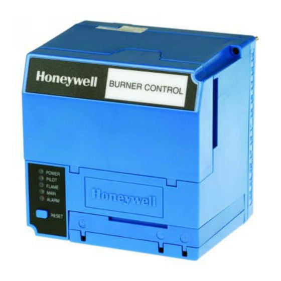
7800 SERIES
Relay Modules
APPLICATION
The RM7897A,C are microprocessor-based integrated burner
controls for automatically fired gas, oil, or combination fuel
single burner applications. The RM7897A,C system consist of
a relay module, subbase, amplifier, and purge card. Options
include keyboard display module (KDM), Personal Computer
Interface, Data ControlBus™ Module, remote display
mounting, Expanded Annunciator and Combustion System
Manager® Software.
Functions provided by the RM7897A,C include automatic
burner sequencing, flame supervision, system status
indication, system or self-diagnostics and troubleshooting.
The RM7897 adds a proof of closure input to the standard
primary control function of the RM7895/RM7896 product. It
adds a blinking fault code function to the POWER LED on
Alarm shutdown. It also adds programmable postpurge using
the S7800A1142 Keyboard Display Module (KDM). The
RM7897A1002 offers selectable pilot operation, intermittent
on terminal 8 or interrupted on terminal 21.
The RM7897C1000 offers interrupted pilot and delayed main
valve for 2-step firing (Low-High-Low) applications.
This document provides installation and static checkout
instructions. Other applicable publications are:
Publication
No.
63-2278
Q7700 Network Interface Unit Product Data
65-0084
Q7800A,B 22-Terminal Wiring Subbase
Product Data
65-0288
S7800A1142 Keyboard Display Module
Product Data
65-0091
S7810A Data ControlBus Module™ Product
Data
65-0095
S7820 Remote Reset Module Product Data
65-0097
221729C Dust Cover Installation
Instructions
65-0101
S7830 Expanded Annunciator Product Data
Product
INSTALLATION INSTRUCTIONS
Publication
No.
65-0102
ZM7850A Combustion System Manager™
Operating Instructions
65-0109
R7824, R7847, R7848, R7849, R7851,
R7861, R7886 Flame Amplifiers for the
7800 Series Product Data
65-0131
221818A Extension Cable Assembly
Product Data
65-0229
7800 SERIES Relay Modules Checkout and
Troubleshooting Product Data.
65-0092
QS7800A ControlBus™ Module, Standard
65-0227
QS7800B ControlBus™ Module, Multidrop
SPECIFICATIONS
Electrical Ratings (See Table 3):
Voltage and Frequency:
RM7897A,C: 120 Vac (+10/-15%), 50/60 Hz (± 10%).
Power Dissipation: 10W maximum.
Maximum Total Connected Load: 2000 VA.
Fusing Total Connected Load: 15A Fast Blow, type SC or
equivalent.
Environmental Ratings:
Ambient Temperature:
Operating: -40°F to 140°F (-40°C to +60°C).
Storage: -40°F to 150°F (-40°C to +66°C).
Humidity: 85% relative humidity continuous, noncondensing.
Vibration: 0.5G environment.
Approvals:
Underwriters Laboratories Inc. Listed: File No. MP268,
Guide No. MCCZ.
Canadian Standards Association Certified: Pending.
Factory Mutual Approved: Report No. Pending.
IRI Acceptable.
Federal Communications Commission: Part 15, Class B,
Emissions.
Product
66-1151
Table of Contents

Related Manuals for Honeywell 7800 Series


Summary of Contents for Honeywell 7800 Series
-
Page 1: Specifications
221818A Extension Cable Assembly mounting, Expanded Annunciator and Combustion System Product Data Manager® Software. 65-0229 7800 SERIES Relay Modules Checkout and Functions provided by the RM7897A,C include automatic Troubleshooting Product Data. burner sequencing, flame supervision, system status 65-0092 QS7800A ControlBus™ Module, Standard indication, system or self-diagnostics and troubleshooting. -
Page 2: Installation
RM7897A1002, RM7897C1000 7800 SERIES RELAY MODULES INSTALLATION 9. This equipment generates, uses and can radiate radio frequency energy and, if not installed and used When Installing this Product… in accordance with the instructions, can cause 1. Read these instructions carefully. Failure to follow them interference with radio communications. -
Page 3: Wiring Subbase
RM7897A1002, RM7897C1000 7800 SERIES RELAY MODULES Wiring Subbase 1. For proper subbase wiring and sequence chart, refer to Fig. 2 and 3. 2. For remote wiring of the Keyboard Display Module, refer to the Specifications for the Keyboard Display Module... - Page 4 RM7897A1002, RM7897C1000 7800 SERIES RELAY MODULES Q7800 FOR DIRECT SPARK IGNITION (OIL OR GAS) IGNITION TRANSFORMER LINE VOLTAGE ALARM MAIN VALVE BURNER MOTOR (BLOWER) (L1) BURNER CONTROLLER/LIMITS RUNNING INTERLOCK (INCLUDING AIRFLOW SWITCH) INTERMITTENT PILOT/IGNITION PREIGNITION MAIN FUEL VALVE(S) INTERLOCK 10-SECOND...
- Page 5 RM7897A1002, RM7897C1000 7800 SERIES RELAY MODULES Q7800 FOR DIRECT SPARK IGNITION (OIL OR GAS) IGNITION TRANSFORMER LINE VOLTAGE ALARM MAIN VALVE BURNER MOTOR (BLOWER) (L1) BURNER CONTROLLER/LIMITS RUNNING INTERLOCK (INCLUDING AIRFLOW SWITCH). 10 SEC. INTERRUPTED PILOT/IGNITION PREIGNITION MAIN FUEL VALVE(S)
-
Page 6: Final Wiring Check
RM7897A1002, RM7897C1000 7800 SERIES RELAY MODULES Table 1. Recommended Wire Sizes and Part Numbers. Application Recommended Wire Size Recommended Part Numbers Line voltage terminals. 14, 16 or 18 AWG copper conductor, 600 volt insulation, TTW60C, THW75C, THHN90C. moisture-resistant wire. Keyboard Display Module 22 AWG two-wire twisted pair with ground, or five-wire. -
Page 7: Static Checkout
RM7897A1002, RM7897C1000 7800 SERIES RELAY MODULES STATIC CHECKOUT external controllers, limits, interlocks, actuators, valves, transformers, motors and other devices are operating properly. After checking all wiring, perform this checkout before installing the RM7897A,C on the subbase. These tests verify the Q7800 Wiring Subbase is wired correctly, and the Table 3. -
Page 8: Equipment Recommended
RM7897A1002, RM7897C1000 7800 SERIES RELAY MODULES Table 5. Composition of each Combination. 4.5A ignition 50 VA Pilot Duty plus 180 VA Ignition plus 2A Pilot Duty 65 VA Pilot Duty plus 4.5A ignition. motor valves with: motor valves with: 660 VA inrush,... -
Page 9: Mounting Other System Components (Fig. 4)
RM7897A1002, RM7897C1000 7800 SERIES RELAY MODULES Table 6. Static Checkout. Test Relay Module Test If Operation is Abnormal, Number Model Jumpers Voltmeter Normal Operation Check Items Listed Below None 5-L2 Line voltage at terminal 5. 1. Master switch. 2. Power connected to master switch. - Page 10 RM7897A1002, RM7897C1000 7800 SERIES RELAY MODULES WIRING SUBBASE RUN/TEST (C,D ONLY) SWITCH H O N E Y W E LL RELAY MODULE CONFIGURATION JUMPERS PURGE TIMER SEQUENCE STATUS LED PANEL POWE R RESET PILOT BUTTON FLAM E MAIN ALAR M...
- Page 11 RM7897A1002, RM7897C1000 7800 SERIES RELAY MODULES Edit: Edit: M22674A M22764B Fig. 10. Confirm Postpurge time. Fig. 7. Select/Restart screen. 1. Press Enter. 7. Press down arrow to select. “Getting Data” will be momentarily displayed, followed by the screen shown in Fig. 8.
-
Page 12: Principal Technical Features
RM7897A1002, RM7897C1000 7800 SERIES RELAY MODULES Once the system is in operation, the settings of the postpurge Loss of flame signal. time can be viewed under Diagnostics, using your S7800 g. Internal system fault occurred. Keyboard Display Module. h. Purge card is removed. -
Page 13: Settings And Adjustments
RM7897A1002, RM7897C1000 7800 SERIES RELAY MODULES Run/Test Switch 1. The Airflow Interlock, burner switch, Run/Test switch and all microcomputer-monitored circuits must also be The Run/Test Switch is located on the top side of the relay in the correct operating state. -
Page 14: Troubleshooting
RM7897A1002, RM7897C1000 7800 SERIES RELAY MODULES Table 7. Site-configurable jumper options. SELECTABLE CONFIGURATION JUMPERS Jumper RUN/TEST SWITCH Number Description Intact Clipped (EC7895C; RM7895C,D; RM7896C,D) Pilot Flame Establishing Period (PFEP) seconds seconds Flame Failure Action Recycle Lockout Airflow Switch (ILK) Failure... - Page 15 RM7897A1002, RM7897C1000 7800 SERIES RELAY MODULES Table 8. Blinking Fault Codes and Recommended Troubleshooting. (Continued) Fault Code System Failure Recommended Troubleshooting Code 2-3 Flame signal value is 1. Make sure the flame detector and flame amplifier are compatible. *Flame Signal too high to be valid.
- Page 16 RM7897A1002, RM7897C1000 7800 SERIES RELAY MODULES Table 8. Blinking Fault Codes and Recommended Troubleshooting. (Continued) Fault Code System Failure Recommended Troubleshooting Code 4-4 The configuration 1. Inspect the jumper connections. Make sure the clipped jumpers were *Configuration jumpers differ from the completely removed.