
Related Manuals for GE Baker Hughes oxy.IQ


Summary of Contents for GE Baker Hughes oxy.IQ
- Page 1 Oxygen oxy.IQ Panametrics Oxygen Analyzer User’s Manual bhge.com 910-296 Rev. E July 2018...
- Page 3 Contact your BHGE representative for the most current information. The Baker Hughes logo is a trade mark of Baker Hughes, a GE company. The GE Monogram is a trademark of the General Electric Company.
- Page 4 [no content intended for this page] oxy.IQ User’s Manual...
-
Page 5: Services
Agreements and more. Please visit more details. Terms and Conditions GE’s sales Terms and Conditions for your recent purchase of a GE product, including the applicable product Warranty, can be found on our website at www.gemeasurement.com/sales-terms-and-conditions the following link:... -
Page 6: Safety Issues
Preface Safety Issues WARNING! It is the responsibility of the user to make sure all local, county, state and national codes, regulations, rules and laws related to safety and safe operating conditions are met for each installation. Attention European Customers! To meet CE Marking requirements for all units intended for use in the EU, all electrical cables must be installed as described in this manual. - Page 7 Preface Qualification of Personnel Make sure that all personnel have manufacturer-approved training applicable to the auxiliary equipment. Personal Safety Equipment Make sure that operators and maintenance personnel have all safety equipment applicable to the auxiliary equipment. Examples include safety glasses, protective headgear, safety shoes, etc. Unauthorized Operation Make sure that unauthorized personnel cannot gain access to the operation of the equipment.
-
Page 8: Regulatory Compliance
Preface Regulatory Compliance Waste Electrical and Electronic Equipment (WEEE) Directive GE is an active participant in Europe’s Waste Electrical and Electronic Equipment (WEEE) take-back initiative (Directive 2012/19/EU). The equipment that you bought has required the extraction and use of natural resources for its production. It may contain hazardous substances that could impact health and the environment. -
Page 9: Table Of Contents
Contents Product Registration ............iii Services . - Page 10 Contents 4.3.3 Adjust the Contrast ......... . 24 The Output Menu .
-
Page 11: Chapter 1. Features And Capabilities
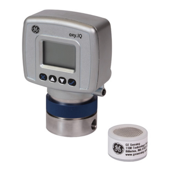
Chapter 1. Features and Capabilities Chapter 1. Features and Capabilities 1.1 Introduction The oxy.IQ Panametrics Oxygen Transmitter (see Figure 1 below) is a highly reliable and cost-effective two-wire, loop-powered transmitter with a linearized 4 to 20 mA output. It measures oxygen content in ten ppm ranges (10, 20, 50, 100, 200, 500, 1000, 2000, 5000 and 10000 ppm) and eight percentage ranges (1, 2, 5, 10, 21, 25, 50 and 100%). -
Page 12: Hazardous Location Certifications
Chapter 1. Features and Capabilities 1.2 Hazardous Location Certifications When equipped with an optional Zener barrier or galvanic isolator, the oxy.IQ can be mounted in a hazardous (classified) location. The oxy.IQ with Intrinsically Safe option is certified to USA, Canadian, ATEX, and international IECEx IS requirements. -
Page 13: Features
Chapter 1. Features and Capabilities 1.4 Features oxy.IQ oxygen sensor uses an advanced galvanic fuel cell that provides superior performance, accuracy, stability and long life. The cell’s innovative design eliminates the potential for negative signal output and reduces sources of contamination. The cell is unaffected by other background gases or hydrocarbons OX-2 OX-4... -
Page 14: Sample Systems
Chapter 1. Features and Capabilities 1.5 Sample Systems In addition to the standard features and options, GE offers a full line of sample handling systems for a variety of applications. If needed, GE can design and build a sample conditioning system to meet unique application requirements. -
Page 15: Chapter 2. Installation
Chapter 2. Installation Chapter 2. Installation 2.1 Mounting the oxy.IQ oxy.IQ To install the into the process or sample system, refer to Figure 9 on page 38 and/or Figure 2 below and proceed to the next page. CONNECTOR 2.05 1.58 Note: All dimensions are inches [mm]. - Page 16 Chapter 2. Installation 2.1 Mounting the oxy.IQ (cont.) Install the oxy.IQ by completing the following steps: 1. Remove the oxy.IQ and the separately-packaged oxygen sensor (see Figure 3 below) from the shipping container. Keep the shipping container and packaging material for possible future use.
- Page 17 Chapter 2. Installation 2.1 Mounting the oxy.IQ (cont.) IMPORTANT: The maximum operating pressure for the oxy.IQ is 10 psi, and the burst pressure of the unit is 200 psi. Be sure the sample conditioning system is designed to maintain the oxy.IQ pressure below these limits, and that the oxy.IQ outlet is vented to atmosphere during operation and calibration.
-
Page 18: Wiring The Oxy.iq
Chapter 2. Installation 2.2 Wiring the oxy.IQ To wire the oxy.IQ, refer to Figure 14 on page 43, then proceed as follows: For IS (Intrinsically Safe) applications, the oxy.IQ WARNING! must be installed with a Zener barrier (see the top of Figure 14 on page 43). Also, for installations in a hazardous location, the blue IS cable (p/n 704-1318-02, 10) must be used. -
Page 19: Longer Cable Lengths
GE offers cables in 2 m and 10 m standard lengths. Longer cable lengths may be used with the oxy.IQ, but these are not available from GE. If you require a longer cable, refer to the following figures for the required cable specifications and construct your own cable for splicing onto the standard GE cable: •... -
Page 20: Installing An Oxygen Sensor
Chapter 2. Installation 2.3 Installing an Oxygen Sensor To install a new or replacement oxygen sensor in the oxy.IQ, refer to Figure 6 below and complete the following steps: Sensor Base Knurled Nut Oxygen Sensor Ring Sensor Manifold Figure 6: Oxygen Sensor Installation 1. - Page 21 Rotate the display as desired and then hand-tighten the blue knurled nut. IMPORTANT: Make sure that the O-ring on the top of the sensor manifold is in place and undamaged. If necessary, contact GE for a replacement. oxy.IQ User’s Manual...
- Page 22 Chapter 2. Installation 2.3 Installing an Oxygen Sensor (cont.) 9. Begin the flow of the process gas. The analog output reading will drop as the oxygen sensor adjusts to the reduced oxygen level. During this time, reset the range as required. 10.
-
Page 23: Chapter 3. Initial Setup & Operation
Chapter 3. Initial Setup & Operation Chapter 3. Initial Setup & Operation 3.1 The oxy.IQ Display and Keypad oxy.IQ All programming of the is done via the front panel keypad and display, as illustrated below. Display Down Arrow Up Arrow Cancel Enter Figure 7: oxy.IQ Display and Keypad... -
Page 24: The Oxy.iq Menu Map
Chapter 3. Initial Setup & Operation 3.2 The oxy.IQ Menu Map As an aid in navigating through the Main Menu, a complete Menu Map of the user program is shown in Figure 16 on page 46. Refer to this figure as needed while programming the oxy.IQ. The oxy.IQ Main Menu consists of the following submenus: •... -
Page 25: Selecting The Output Range
Chapter 3. Initial Setup & Operation 3.3.1 Selecting the Output Range To select the desired measurement range, complete the following steps: 1. Press the Enter key to enter the Main Menu. 2. Press the Enter key twice and then press the key to enter the Output menu. -
Page 26: Trimming The Analog Output
Chapter 3. Initial Setup & Operation 3.3.2 Trimming the Analog Output To trim the analog output, calibrate the low (4 mA) end of the output then the high (20 mA) end of the output. IMPORTANT: The 4 mA and 20 mA adjustments interact with each other. -
Page 27: Air Calibration
Chapter 3. Initial Setup & Operation 3.3.2c Trimming the Analog Output High (20 mA) End 1. Press the Enter key and then press the key to enter the 20 mA Trim menu, and the analog output is driven to about 20 mA. 2. - Page 28 Chapter 3. Initial Setup & Operation 3.3.3a Calibrating a New Sensor For a new sensor, continue the air calibration procedure as follows: 1. Press the Enter key and then press the key to select the YES menu option. 2. Press the Enter key to acknowledge that you are resetting the sensor lifetime clock.
-
Page 29: Span Gas Calibration
Chapter 3. Initial Setup & Operation 3.3.4 Span Gas Calibration Before beginning the span gas calibration, make sure the oxy.IQ is indicating an O level less than the span gas value, to ensure an accurate calibration. Then, start the flow of the span gas to the sensor. - Page 30 Chapter 3. Initial Setup & Operation [no content intended for this page] oxy.IQ User’s Manual...
-
Page 31: Chapter 4. User Programming
Chapter 4. User Programming Chapter 4. User Programming 4.1 Introduction IMPORTANT: The oxy.IQ Service menu is for use by qualified service personnel only and requires a special passcode for access. That menu is not discussed in this chapter. This chapter provides instructions for programming all of the oxy.IQ menu options available to the user, which can be accessed without the use of a passcode. -
Page 32: Sensor Life
Chapter 4. User Programming 4.2.3 Sensor Life To read the sensor life, complete the following steps: 1. Press the Enter key to enter the Main Menu. 2. Press the Enter key to enter the Calibration menu. 3. Press the Enter key three times and then press the key to enter the Sensor Life menu. -
Page 33: The Display Menu
Chapter 4. User Programming 4.3 The Display Menu Proceed to the appropriate section to program the desired menu option. 4.3.1 Select the O2 Parameter To select the O2 parameter for display, complete the following steps: 1. Press the Enter key to enter the Main Menu. 2. -
Page 34: Display The Sensor Range
Chapter 4. User Programming 4.3.2 Display the Sensor Range To select whether or not the O2 range of the installed sensor is displayed, complete the following steps: 1. Press the Enter key to enter the Main Menu. 2. Press the Enter key once and then press the key to enter... -
Page 35: The Output Menu
Chapter 4. User Programming 4.4 The Output Menu Proceed to the appropriate section to program the desired menu option. 4.4.1 Range See “Selecting the Output Range” on page 15. 4.4.2 Trim See “Trimming the Analog Output” on page 16. 4.4.3 Error Type To select the process conditions that will activate an on-screen warning and send an alarm to the analog output device, complete the following steps:... - Page 36 Chapter 4. User Programming 4.4.3 Error Type (cont.) 4. Use the keys to select the desired option and then Enter press the key to activate that error type. A check mark will appear next to the selected option to indicate that it is activated.
-
Page 37: Error Output
Chapter 4. User Programming 4.4.4 Error Output To select the desired output value that will be sent to the analog output device upon an error, complete the following steps: 1. Press the Enter key to enter the Main Menu. 2. Press the Enter key twice and then press the key to enter... - Page 38 Chapter 4. User Programming [no content intended for this page] oxy.IQ User’s Manual...
-
Page 39: Chapter 5. The Service Menu
Chapter 5. The Service Menu Chapter 5. The Service Menu CAUTION! The Service Menu is intended for use by qualified service personnel only, and access to this menu requires entry of the service passcode. Misuse of the information in this menu may significantly impair the accuracy and performance of your oxy.IQ and may cause it to fail to meet its published specifications. -
Page 40: Diagnostics
Chapter 5. The Service Menu 5.2.1 Diagnostics To enter the Diagnostics menu option from the Service Menu, complete the following steps: 1. Use the keys as necessary to highlight the Diagnostics menu option. 2. Press the Enter key to enter the Diagnostics menu. 3. -
Page 41: Chapter 6. Specifications
Chapter 6. Specifications Chapter 6. Specifications 6.1 Intrinsically Safe (IS) Installation Intrinsically safe installations require an MTL7706 zener barrier, one IS cable, and one non-IS cable. Power Requirements 24 to 28 VDC at 50 mA Cable p/n 704-1318-02 (2 m length) or p/n 704-1317-10 (10 m length) blue jacketed, twisted-pair with connector, 26 AWG conductors, with connector Output... -
Page 42: All Installations
Chapter 6. Specifications 6.3 All Installations Process Wetted Materials ® SS process unit: 316 stainless steel, Viton O-ring, gold-plated sensor electrical contacts, and glass User-Selectable Measurement Ranges • PPM sensors: - 0 to 10 ppm (OX-1 or OX-2 only) - 0 to 20 ppm (OX-1 or OX-2 only) - 0 to 50 ppm (OX-1 or OX-2 only) - Page 43 Chapter 6. Specifications 6.3 All Installations (cont.) Repeatability • ±1% of range • ±2% of range for the 0 to 10 ppm range (OX-1, 2) Resolution ±0.1% of range Linearity • ±2% of range (OX-1, 2, 3, 5) • ±5% of range (OX-4) Sensor Operating Temperature 32°F to 113°F (0°C to 45°C) Sample Pressure...
- Page 44 Chapter 6. Specifications 6.3 All Installations (cont.) Sample Flow Rate 1.0 SCFH (500 cc/min) recommended for process units Electrical Classification Intrinsically Safe package with zener barrier or galvanic isolator: • USA/Canada: IS for Class I, Div 1, Groups A, B, C, D; T4 IS for Class I, Zone 0, AEx ia IIC T4;...
-
Page 45: Product Label
Chapter 6. Specifications 6.4 Product Label A typical product label is shown in Figure 8 below: II 1 G Figure 8: oxy.IQ Label - IS Package Option oxy.IQ User’s Manual... - Page 46 Chapter 6. Specifications [no content intended for this page] oxy.IQ User’s Manual...
-
Page 47: Appendix A. Outline And Installation Drawings
Appendix A. Outline and Installation Drawings Appendix A. Outline and Installation Drawings oxy.IQ This appendix includes the following drawings: • “Outline & Installation (ref. dwg. 712-1840)” on page 38 • “Cable, Standard (ref. dwg. 704-1317, SH 1 of 2)” on page 39 •... -
Page 48: Outline & Installation (Ref. Dwg. 712-1840)
Appendix A. Outline and Installation Drawings Figure 9: Outline & Installation (ref. dwg. 712-1840) oxy.IQ User’s Manual... -
Page 49: Cable, Standard (Ref. Dwg. 704-1317, Sh 1 Of 2)
Appendix A. Outline and Installation Drawings Figure 10: Cable, Standard (ref. dwg. 704-1317, SH 1 of 2) oxy.IQ User’s Manual... -
Page 50: Cable, Standard (Ref. Dwg. 704-1317, Sh 2 Of 2)
Appendix A. Outline and Installation Drawings Figure 11: Cable, Standard (ref. dwg. 704-1317, SH 2 of 2) oxy.IQ User’s Manual... -
Page 51: Cable, Is (Ref. Dwg. 704-1318, Sh 1 Of 2)
Appendix A. Outline and Installation Drawings Figure 12: Cable, IS (ref. dwg. 704-1318, SH 1 of 2) oxy.IQ User’s Manual... -
Page 52: Cable, Is (Ref. Dwg. 704-1318, Sh 2 Of 2)
Appendix A. Outline and Installation Drawings Figure 13: Cable, IS (ref. dwg. 704-1318, SH 2 of 2) oxy.IQ User’s Manual... -
Page 53: Wiring Options (Ref. Dwgs. 702-285 & 702-286)
Appendix A. Outline and Installation Drawings Hazardous Location Non-Hazardous Location POWER SUPPLY ZBB BUS BAR BROWN +24V GREEN BLUE 24V RETURN oxy.IQ Transmitter MTL7706 IS GROUND 4-20MA ANALOG IS Cable 704-1318-xx INPUT DEVICE (Blue Jacket) Non-IS Cable 1. Equipment connected to barrier inputs must not use or generate more than 250V. -
Page 54: Schematic Diagram (Ref. Dwg. 752-347)
Appendix A. Outline and Installation Drawings Figure 15: Schematic Diagram (ref. dwg. 752-347) oxy.IQ User’s Manual... -
Page 55: Appendix B. Menu Maps
Appendix B. Menu Maps Appendix B. Menu Maps oxy.IQ This appendix includes the User Menu Maps (please note the Service Menu Map is available to qualified BHGE field service personnel only). oxy.IQ User’s Manual... - Page 56 Appendix B. Menu Maps Figure 16: User’s Menu Map oxy.IQ User’s Manual...
- Page 57 Appendix B. Menu Maps Figure 17: Service Menu Map oxy.IQ User’s Manual...
- Page 58 Appendix B. Menu Maps [no content intended for this page] oxy.IQ User’s Manual...
-
Page 59: Appendix C. Order String
Appendix C. Order String Appendix C. Order String oxy.IQ BCD-E Model Only oxy.IQ Oxygen Transmitter; 4 to 20 mA output Sensor No sensor Standard ppm, 0 to 10, 20, 50, 100, 200, 500, 1000 ppm Acid ppm, 0 to 10, 20, 50, 100, 200, 500, 1000 ppm Standard percent sensor Acid percent sensor Standard ppm, 0 to 100, 200, 500 and 1000 ppm... - Page 60 Appendix C. Order String [no content intended for this page] oxy.IQ User’s Manual...
-
Page 61: Appendix D. Certifications
Appendix D. Certifications Appendix D. Certifications The following oxy.IQ certifications are included in this appendix: • “ATEX EU-Type Examination Certificate” on page 52 • “ATEX IECEx MAM Ex Certificate” on page 56 • “Canadian Certificate of Compliance” on page 58 •... -
Page 62: Atex Eu-Type Examination Certificate
Equipment or protective system: Model oxy.IQ Oxygen Transmitter (Type Reference and Name) Name of Applicant: GE Infrastructure Sensing Address of Applicant: 1100 Technology Park Drive Billerica, MA 01821 This equipment or protective system and any acceptable variation thereto is specified in the schedule to this certificate and documents therein referred to. - Page 63 Appendix D. Certifications D.1 ATEX EU-Type Examination Certificate (cont.) SCHEDULE to EU-Type Examination Certificate No. FM14ATEX0032X Description of Equipment or Protective System: The Model oxy.IQ is a two-wire, loop-powered transmitter for measuring oxygen in ten ppm ranges and seven percentage ranges. The Model oxy.IQ Transmitter contains one of five different oxygen cells. The cells are specified to be part numbers OX-1, OX-2, OX-3 and OX-4 and OX-5.
- Page 64 Appendix D. Certifications D.1 ATEX EU-Type Examination Certificate (cont.) SCHEDULE to EU-Type Examination Certificate No. FM14ATEX0032X Certificate History Details of the supplements to this certificate are described below: Date Description 24th February 2015 Original Issue. Supplement 1: Report Reference: RR203799 dated 26th January 2016 28th January 2016 Description of the Change: 1.
- Page 65 Appendix D. Certifications D.1 ATEX EU-Type Examination Certificate (cont.) Blueprint Report GE Infrastructure Sensing Inc (1000000179) Class No 3610 Original Project I.D. 3047174 Certificate I.D. FM14ATEX0032X Drawing No. Revision Level Drawing Title Last Report Electronic Drawing 714-1344 Oxy.IQ Safety Manual...
-
Page 66: Atex Iecex Mam Ex Certificate
Appendix D. Certifications D.2 ATEX IECEx MAM Ex Certificate oxy.IQ User’s Manual... - Page 67 Appendix D. Certifications D.2 ATEX IECEx MAM Ex Certificate (cont.) oxy.IQ User’s Manual...
-
Page 68: Canadian Certificate Of Compliance
FM17CA0101X Equipment: Model oxy.IQ Oxygen Transmitter (Type Reference and Name) Name of Listing Company: GE Infrastructure Sensing Address of Listing Company: 1100 Technology Park Drive Billerica, MA 01821 The examination and test results are recorded in confidential report number: 3047174 dated 3... - Page 69 Appendix D. Certifications D.3 Canadian Certificate of Compliance (cont.) SCHEDULE Canadian Certificate Of Conformity No: FM17CA0101X The marking of the equipment shall include: IS CL I DIV 1, GPS A, B, C, D; CL I, DIV 2, GPS ABCD Class I, Zone 0, Ex ia IIC T4 Ga Tamb = -20°C to +60°C Install per Control Drawing 752-347 Description of Equipment:...
-
Page 70: Fm Certificate Of Compliance
Appendix D. Certifications D.3 Canadian Certificate of Compliance (cont.) SCHEDULE Canadian Certificate Of Conformity No: FM17CA0101X Schedule Drawings A copy of the technical documentation has been kept by FM Approvals. Certificate History Details of the supplements to this certificate are described below: Date Description February 2015... -
Page 71: Fm Certificate Of Compliance
FM17US0190X Equipment: Model oxy.IQ Oxygen Transmitter (Type Reference and Name) Name of Listing Company: GE Infrastructure Sensing Address of Listing Company: 1100 Technology Park Drive Billerica, MA 01821 The examination and test results are recorded in confidential report number: 3047174 dated 3... -
Page 72: Iecex Certificate Of Conformity
Appendix D. Certifications D.4 FM Certificate of Compliance (cont.) SCHEDULE US Certificate Of Conformity No: FM17US0190X The marking of the equipment shall include: IS CL I DIV 1, GPS A, B, C, D; CL I, DIV 2, GPS ABCD Class I, Zone 0, AEx ia IIC T4 Ga Tamb = -20°C to +60°C Install per Control Drawing 752-347 Description of Equipment:... - Page 73 Appendix D. Certifications D.4 FM Certificate of Compliance (cont.) SCHEDULE US Certificate Of Conformity No: FM17US0190X Schedule Drawings A copy of the technical documentation has been kept by FM Approvals. Certificate History Details of the supplements to this certificate are described below: Date Description February 2015...
-
Page 74: Iecex Certificate Of Conformity
Appendix D. Certifications D.5 IECEx Certificate of Conformity oxy.IQ User’s Manual... - Page 75 Appendix D. Certifications D.5 IECEx Certificate of Conformity (cont.) oxy.IQ User’s Manual...
- Page 76 Appendix D. Certifications D.5 IECEx Certificate of Conformity (cont.) oxy.IQ User’s Manual...
- Page 77 Appendix D. Certifications D.5 IECEx Certificate of Conformity (cont.) oxy.IQ User’s Manual...
-
Page 78: Analog Output
Index Adjusting, oxy.IQ ..........14 Air Calibration . -
Page 79: Main Menu
Index Error Output Value ..........27 Type, Selecting . -
Page 80: Oxygen Sensor
Index O2 Display Parameter, Selecting ........23 Order String . - Page 81 Index RoHS Compliance ..........vi Safety Auxiliary Equipment.
-
Page 82: Addendum A. Oxy.iq Safety Manual
• The product cannot be repaired by the user; it must be replaced by an equivalent certified product. Repairs should only be carried out by the manufacturer or by an approved repairer. Please contact GE Customer Support Center for repair, maintenance or replacement of the product. For oxygen sensor replacements please contact GE Customer Support Center. - Page 83 DWG NO. 714-1344 REV. C TITLE • Only trained, competent personnel may install, operate and maintain the equipment. • For product training please contact GE Customer Support Center: U.S.A Ireland The Boston Center GE Sensing EMEA 1100 Technology Park Drive...
- Page 84 Addendum A. oxy.IQ Safety Manual GE Sensing oxy.IQ Oxy.IQ Safety Manual 1100 Technology Park Drive Billerica, MA 01821 MODEL DWG NO. 714-1344 REV. C TITLE Markings Markings shall appear on the oxy.IQ as shown below for the Intrinsically Safe version of the product.
- Page 85 Addendum A. oxy.IQ Safety Manual GE Sensing oxy.IQ Oxy.IQ Safety Manual 1100 Technology Park Drive Billerica, MA 01821 MODEL DWG NO. 714-1344 REV. C TITLE Connection and Wiring Diagram The following diagram is the entity parameters for the oxy.IQ. Page 5 of 6...
- Page 86 Addendum A. oxy.IQ Safety Manual GE Sensing oxy.IQ Oxy.IQ Safety Manual 1100 Technology Park Drive Billerica, MA 01821 MODEL DWG NO. 714-1344 REV. C TITLE Power Requirements: Nominal Operating Parameters: 28VDC at 50mA Blue (+) Brown (-) Power Connector Page 6 of 6...
- Page 87 Addendum A. oxy.IQ Safety Manual [no content intended for this page] oxy.IQ User’s Manual...
- Page 88 EU DECLARATION Sensing CONFORMITY DOC-0046, Rev. C GE Sensing 1100 Technology Park Drive Billerica, MA 01821 declare under our sole responsibility that the oxy.IQ™ Oxygen Transmitter to which this declaration relates, is in conformity with the following standards: • EN 60079-0:2012+A11:2013 •...
- Page 89 [no content intended for this page]...
- Page 91 Contact your BHGE representative for the most current information. The Baker Hughes logo is a trade mark of Baker Hughes, a GE company. The GE Monogram is a trademark of the General Electric Company.