Table of Contents

Related Manuals for Emerson Branson 2000 Series

Summary of Contents for Emerson Branson 2000 Series
- Page 1 100-214-251 IWoper.book Page i Friday, June 16, 2017 4:12 PM 100-214-251 - REV. 05 2000IW/IW+ Integrated Welder I n s t r u c t i o n M a n u a l Branson Ultrasonics Corporation 41 Eagle Road Danbury, CT 06813-1961 USA (203) 796-0400 http://www.bransonultrasonics.com...
- Page 2 100-214-251 IWoper.book Page i Friday, June 16, 2017 4:12 PM Manual Change Information At Branson, we strive to maintain our position as the leader in ultrasonics plastics joining, cleaning and related technologies by continually improving our circuits and components in our equipment.
- Page 3 100-214-251 IWoper.book Page ii Friday, June 16, 2017 4:12 PM Foreword Congratulations on your choice of a Branson Ultrasonics Corporation system! The Branson 2000-Series system is process equipment for the joining of plastic parts using ultrasonic energy. It is the newest generation of product using this sophisticated technology for a variety of customer applications.
-
Page 4: Table Of Contents
100-214-251 IWoper.book Page iii Friday, June 16, 2017 4:12 PM Table Of Contents Chapter 1: Safety and Support Safety Requirements and Warnings ........2 General Precautions . - Page 5 100-214-251 IWoper.book Page iv Friday, June 16, 2017 4:12 PM Ultrasonic Test ..........108 Horn Down .
- Page 6 100-214-251 IWoper.book Page v Friday, June 16, 2017 4:12 PM List Of Figures Chapter 1: Safety and Support Figure 1.1 Safety Labels on the 2000IW/IW+ Integrated Welder ..... . 3 Figure 1.2 Safety Label on Left Door of the 2000IW/IW+ Integrated Welder .
- Page 7 100-214-251 IWoper.book Page vi Friday, June 16, 2017 4:12 PM Chapter 7:Maintenance Figure 7.1 Reconditioning Stack Surfaces ........114 Figure 7.2 Disassembly of Air Filter Components .
- Page 8 100-214-251 IWoper.book Page vii Friday, June 16, 2017 4:12 PM List Of Tables Chapter 1: Safety and Support Table 1.1 Warranty Period ..........6 Table 1.2 Branson Contact .
- Page 9 100-214-251 IWoper.book Page viii Friday, June 16, 2017 4:12 PM viii 100-214-251 REV. 05...
-
Page 10: Chapter 1: Safety And Support
100-214-251 IWoper.book Page 1 Friday, June 16, 2017 4:12 PM Chapter 1: Safety and Support Safety Requirements and Warnings ......2 General Precautions . -
Page 11: Safety Requirements And Warnings
100-214-251 IWoper.book Page 2 Friday, June 16, 2017 4:12 PM Safety Requirements and Warnings This chapter contains an explanation of the different Safety Notice symbols and icons found both in this manual and on the product itself and provides additional safety information for ultrasonic welding. -
Page 12: Figure 1.1 Safety Labels On The 2000Iw/Iw+ Integrated Welder
100-214-251 IWoper.book Page 3 Friday, June 16, 2017 4:12 PM 1.1.2 Symbols Found on the Product Familiar graphic warning symbols are used to alert the user to items of concern or hazard. The following warning symbols appear on the 2000IW/ IW+ Integrated Welder. Figure 1.1 Safety Labels on the 2000IW/IW+ Integrated Welder Figure 1.2 Safety Label on Left Door of the 2000IW/IW+ Integrated Welder 100-214-251 REV. -
Page 13: General Precautions
100-214-251 IWoper.book Page 4 Friday, June 16, 2017 4:12 PM General Precautions Take the following precautions before servicing the power supply, or setting DIP switches: • Be sure the power switch is in the Off position before making any electrical connections. •... - Page 14 Chapter 1: Safety and Support. 1.2.5 Regulatory Compliance The Branson 2000 Series Integrated Welder is designed for compliance with the following regulatory and agency standards: • ANSI Z535.1 Safety Color Code • ANSI Z535.3 Criteria for Safety Symbols • ANSI Z535.4 Product Safety Signs and Labels •...
-
Page 15: Warranty Statement, Disclaimer
100-214-251 IWoper.book Page 6 Friday, June 16, 2017 4:12 PM Warranty Statement, Disclaimer The following excerpts from the “Terms and Conditions of Sale” (found on the back of your Invoice) are essential guidelines for the product Warranty issued with your Branson ultrasonic welding components. - Page 16 100-214-251 IWoper.book Page 7 Friday, June 16, 2017 4:12 PM Warranty Service covers the following: Repair service at Branson's main repair facility or a regional office • Includes parts and labor performed at Branson authorized repair facilities. The customer must return the equipment properly packed with all shipping charges prepaid Repair service at the customer site •...
-
Page 17: How To Contact Branson
100-214-251 IWoper.book Page 8 Friday, June 16, 2017 4:12 PM How to Contact Branson Branson is here to help you. We appreciate your business and are interested in helping you successfully use our products. To contact Branson for help, use the following telephone numbers, or contact the field office nearest you (business hours from 8 a.m. -
Page 18: Returning Equipment For Repair
100-214-251 IWoper.book Page 9 Friday, June 16, 2017 4:12 PM Returning Equipment for Repair Before sending equipment for repair, provide as much information with the equipment to help determine the problem with the system. Use the following page to record necessary information. -
Page 19: Table 1.2 Branson Contact
100-214-251 IWoper.book Page 10 Friday, June 16, 2017 4:12 PM _______________________________________________________________________ _______________________________________________________________________ 6. What is your application? (Type of weld, plastic material, etc.) _______________________________________________________________________ 7. Name and phone number of the person most familiar with the problem: _______________________________________________________________________ _______________________________________________________________________ 8. Contact the Branson office prior to shipping the equipment. 9. - Page 20 100-214-251 IWoper.book Page 11 Friday, June 16, 2017 4:12 PM 1.5.4 Pack and Ship the Equipment 1. Carefully pack the system in original packing material to avoid shipping damage. Plainly show the RGA number on the outside of cartons as well as inside the carton along with the reason for return.
-
Page 21: Obtaining Replacement Parts
100-214-251 IWoper.book Page 12 Friday, June 16, 2017 4:12 PM Obtaining Replacement Parts You can reach Branson Parts Store at the following telephone numbers: Branson Part Store direct telephone number: 877-330-0406 fax number: 877-330-0404 Many parts can be shipped the same day if ordered before 2:30 p.m., Eastern time. A parts list is found in Chapter 7: Maintenance of this manual, listing descriptions and EDP... -
Page 22: Chapter 2:The 2000Iw/Iw+ Welder
100-214-251 IWoper.book Page 13 Friday, June 16, 2017 4:12 PM Chapter 2: The 2000IW/IW+ Welder Models Covered ......... 14 Overview of these Models . -
Page 23: Models Covered
100-214-251 IWoper.book Page 14 Friday, June 16, 2017 4:12 PM Models Covered This manual contains instructions for installing, setting up and operating a 2000IW and 2000IW+ Series Integrated Welders for 1100, 2200, and 3300 Watt output. 100-214-251 REV. 05... -
Page 24: Overview Of These Models
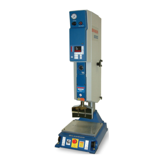
100-214-251 IWoper.book Page 15 Friday, June 16, 2017 4:12 PM Overview of these Models Figure 2.1 2000IW/IW+ Series Integrated Welder The 2000IW and IW+ Series Integrated Welders are ultrasonic plastic joining systems. They are used for welding plastic parts together by staking, insertion, swaging and degating. - Page 25 100-214-251 IWoper.book Page 16 Friday, June 16, 2017 4:12 PM 2.2.1 Carriage and Slide System The carriage is driven by a double-acting air cylinder, mounted on a linear, ball-bearing slide. The slide system is based on eight sets of preloaded, permanently lubricated bearings.
- Page 26 100-214-251 IWoper.book Page 17 Friday, June 16, 2017 4:12 PM 2.2.6 Upper Limit Switch The optical Upper Limit Switch (ULS) signals the control circuits in the Controller that the carriage has returned to the top of its stroke and the welder is ready to start another weld cycle.
-
Page 27: Compatibility With Branson Products
100-214-251 IWoper.book Page 18 Friday, June 16, 2017 4:12 PM Compatibility with Branson Products The 2000IW/IW+ Series Integrated Welders are compatible for use with either a standard base or a hub for automation. The CJ20 converter is used for the 1100, 2200, and 3300 Watt units. -
Page 28: Features
100-214-251 IWoper.book Page 19 Friday, June 16, 2017 4:12 PM Features The 2000IW/IW+ Series Integrated Welders can perform ultrasonic welding, inserting, staking, spot welding, swaging, degating, and continuous ultrasonic operations. It is designed for automated, semi-automated and/or manual production operations. The following list describes the control features of the welder. -
Page 29: Front Panel Controls
100-214-251 IWoper.book Page 20 Friday, June 16, 2017 4:12 PM Front Panel Controls Figure 2.2 Front Panel Controls, IW Table 2.1 Front Panel Controls IW Item Name Function Indicates the amount of air pressure applied to a Pressure Gauge cylinder; dual-calibrated at 0-100 psig/o-700 kPa. Adjusts amount of air pressure applied to cylinder;... - Page 30 100-214-251 IWoper.book Page 21 Friday, June 16, 2017 4:12 PM Table 2.1 Front Panel Controls IW Item Name Function Autotune Label Refer to Section 7.4.1 Manual Tuning Front Panel Displays Refer to next Section Provides a quick method of determining relative Stroke Indicator carriage travel during a weld cycle;...
-
Page 31: Figure 2.3 Front Panel Displays, Iw
100-214-251 IWoper.book Page 22 Friday, June 16, 2017 4:12 PM Figure 2.3 Front Panel Displays, IW Table 2.2 Front Panel Displays, IW Item Name Function This 20 segment bargraph displays the power level during the Test mode; or the power applied to the workpiece during a weld cycle. - Page 32 100-214-251 IWoper.book Page 23 Friday, June 16, 2017 4:12 PM Table 2.2 Front Panel Displays, IW Item Name Function Activates ultrasonic power and places the ultrasonic power supply module into Test (autotune) mode for approximately 6 seconds). While this switch is pressed, power displays on both the NUMERIC DISPLAY and the POWER BARGRAPH.
-
Page 33: Figure 2.4 Front Panel Displays, Iw
100-214-251 IWoper.book Page 24 Friday, June 16, 2017 4:12 PM Figure 2.4 Front Panel Displays, IW+ Table 2.3 Front Panel Displays, IW+ Item Name Function This 20 segment bargraph displays the power level during the Test mode; or the power applied to the workpiece during a weld cycle. - Page 34 100-214-251 IWoper.book Page 25 Friday, June 16, 2017 4:12 PM Table 2.3 Front Panel Displays, IW+ Item Name Function Resets any resettable or latchable alarm condition (indicated by the switch LED blinking). Holding RESET Reset Switch prevents a weld cycle from starting. Releasing RESET returns the welder to the ready state, if there are no non-resettable errors.
- Page 35 100-214-251 IWoper.book Page 26 Friday, June 16, 2017 4:12 PM Table 2.3 Front Panel Displays, IW+ Item Name Function Selects between Time and Collapse and Absolute Mode Switch, a Distance modes; changes the display for the selected 2000IW+ only mode, and allows for changes in mode or mode feature parameters when Display Lock is inactive.
-
Page 36: Rear Panel
100-214-251 IWoper.book Page 27 Friday, June 16, 2017 4:12 PM Rear Panel The grayed out portion shows placement of the optional Accessory Input/Output (1), and Ground Detect inputs (2, 3) and the position of the mounting plate supplied in their respective kits (see below). - Page 37 100-214-251 IWoper.book Page 28 Friday, June 16, 2017 4:12 PM Table 2.4 Rear Panel Item Name Function Ground Detect, 15 An optional 2000IW only feature, allows ultrasonic pin female connector energy to be turned off when the horn comes in contact with your electrically isolated fixture or anvil.
-
Page 38: System Inputs/Outputs
100-214-251 IWoper.book Page 29 Friday, June 16, 2017 4:12 PM System Inputs/Outputs The inputs provided to the welder are used to control the weld cycle and monitor the 2000IW/IW+ hardware. 2.7.1 START SWITCHES/START Signal - START Connector These inputs are used to start the weld cycle. To start a weld cycle, both START SWITCH inputs must become active within 100 (IW) or 200 (IW+) ms of each other, and remain active until TRS activates, or an error will be generated and no weld will be performed Errors will also be generated if the START SWITCHES do not remain active until the TRS... - Page 39 100-214-251 IWoper.book Page 30 Friday, June 16, 2017 4:12 PM 2.7.5 WELD ON Signal - Alarm Connector The WELD ON signal indicates you are in the Weld Time portion of the cycle and that TRS is active. This signal indicates when a start signal can be released. In any of he following situations, an error will be generated: •...
-
Page 40: Glossary Of Terms
100-214-251 IWoper.book Page 31 Friday, June 16, 2017 4:12 PM Glossary of Terms The following terminology may be encountered when using or operating a 2000-series ultrasonic welding system. Some of these terms may not be available in all configurations: AB Amplitude: The amplitude at the horn face during the afterburst step. AB Delay: Time delay between the end of the hold and the start of afterburst. - Page 41 100-214-251 IWoper.book Page 32 Friday, June 16, 2017 4:12 PM Downspeed: The rate of speed of the actuator from the home position to the part. General Alarm: An alarm that occurs due to a system fault and/or tripping a limit. Ground Det.
-
Page 42: Chapter 3:Delivery And Handling
100-214-251 IWoper.book Page 33 Friday, June 16, 2017 4:12 PM Chapter 3: Delivery and Handling Shipping and Handling ........34 Receiving . -
Page 43: Shipping And Handling
100-214-251 IWoper.book Page 34 Friday, June 16, 2017 4:12 PM Shipping and Handling CAUTION General Warning The Integrated Welder internal components are sensitive to static discharge. Many components can be harmed if the unit is dropped, shipped under improper conditions or otherwise mishandled. 3.1.1 Environmental Specifications The Integrated Welder is an electronic unit that converts line voltage to ultrasonic energy... -
Page 44: Receiving
100-214-251 IWoper.book Page 35 Friday, June 16, 2017 4:12 PM Receiving The Integrated Welder is a sensitive electronic device. Many of its components can be harmed if the unit is dropped or otherwise mishandled. CAUTION Heavy Object The Integrated Welder is heavy. Handling, unpacking, and installation may require assistance or the use of a lifting device. -
Page 45: Unpacking
100-214-251 IWoper.book Page 36 Friday, June 16, 2017 4:12 PM Unpacking The Integrated Welder is fully assembled. It is shipped in a sturdy cardboard box. Some additional items are shipped in the box with the Integrated Welder. Table 3.3 When unpacking the Integrated Welder, take the following steps Step Action Unpack the Integrated Welder as soon as it arrives. -
Page 46: Returning Equipment
100-214-251 IWoper.book Page 37 Friday, June 16, 2017 4:12 PM Returning Equipment If you are returning equipment to Branson Ultrasonic Corporation, please call your Customer Service Representative to receive approval to return goods to Danbury. If you are returning equipment for repair refer to Chapter 1: Safety and Support, Section 1.5 Returning Equipment for... - Page 47 100-214-251 IWoper.book Page 38 Friday, June 16, 2017 4:12 PM 100-214-251 REV. 05...
-
Page 48: Chapter 4: Installation And Setup
100-214-251 IWoper.book Page 39 Friday, June 16, 2017 4:12 PM Chapter 4: Installation and Setup About Installation........40 Handling and Unpacking. -
Page 49: About Installation
100-214-251 IWoper.book Page 40 Friday, June 16, 2017 4:12 PM About Installation This Chapter is intended to help the installer with the basic installation and setup of your new 2000 Series Integrated Welder. This chapter will bring the reader to the point at which the system is functionally “ready to weld”. -
Page 50: Handling And Unpacking
100-214-251 IWoper.book Page 41 Friday, June 16, 2017 4:12 PM Handling and Unpacking If there are any visible signs of damage to the shipping containers or the product, or you later discover hidden damage, NOTIFY YOUR CARRIER IMMEDIATELY. Save the packing material. -
Page 51: Figure 4.2 Unpacking The Stand (2000Iw/Iw+ On A Hub); Hub Shown Separately
100-214-251 IWoper.book Page 42 Friday, June 16, 2017 4:12 PM CAUTION General Warning The column and column support are under spring tension from the counterbalance spring. Do NOT attempt to disassemble the column from the stand, but always keep the column support clamped together. -
Page 52: Figure 4.3 Ultrasonic Converter (J-Type For Stand Use) And Booster
100-214-251 IWoper.book Page 43 Friday, June 16, 2017 4:12 PM 1. Move the shipping container close to the intended installation location, leave it on the floor 2. Cut the two vertical packing straps, and open the top of the box. Remove the insert from the top of the box, which can contain the booster, converter, and the toolkit. -
Page 53: Take Inventory Of Small Parts
100-214-251 IWoper.book Page 44 Friday, June 16, 2017 4:12 PM Take Inventory of Small Parts Table 4.1 Small Parts Included (=x) with IW/IW+ integrated Welder Part or Kit 20kHz Stand (Base) Stand (Hub) T-Handle Wrench Mylar Washer Kit 20kHz Spanners (2) Fixture Bolts and Washer M8 Allen Wrench 4.3.1... -
Page 54: Installation Requirements
100-214-251 IWoper.book Page 45 Friday, June 16, 2017 4:12 PM Installation Requirements This section covers the location options, dimensions of the major assemblies, environmental requirements, electrical requirements and factory air requirements, to help you plan and execute your installation successfully. 4.4.1 Location The Integrated Welder should only be operated in the vertical position. -
Page 55: Figure 4.4 2000Iw/Iw+ Integrated Welder Dimensional Drawing
100-214-251 IWoper.book Page 46 Friday, June 16, 2017 4:12 PM Figure 4.4 2000IW/IW+ Integrated Welder Dimensional Drawing 4.4.2 Environmental Specifications Table 4.3 Environmental Specifications Environmental Concern Acceptable Range Humidity 30% to 95%, non-condensing 100-214-251 REV. 05... -
Page 56: Table 4.4 Input Power Requirements
100-214-251 IWoper.book Page 47 Friday, June 16, 2017 4:12 PM Table 4.3 Environmental Specifications Environmental Concern Acceptable Range Ambient Operating Temperature +5° C to +50° C (41° F to 122° F) Operating Altitude Up to 1000 m IP Rating 4.4.3 Electrical Input Power Ratings Plug the Welder into a single-phase, grounded, 3-wire, 50 or 60 Hz power source. -
Page 57: Figure 4.5 Hooking Up The Air Line
100-214-251 IWoper.book Page 48 Friday, June 16, 2017 4:12 PM 4.4.4.1 Air Filter The 2000IW/IW+ Integrated Welders have an input air filter which protects from particulate matter of 5 microns or larger. 4.4.4.2 Pneumatic Connections Air connection to the unit is made to the AIR INLET connector on the lower rear of the Integrated Welder, with plastic pneumatic tubing. -
Page 58: Installation Steps
100-214-251 IWoper.book Page 49 Friday, June 16, 2017 4:12 PM Installation Steps CAUTION Heavy Object This product is heavy and can cause a pinching or crushing injury during installation or adjustment. Keep clear of moving parts and do not loosen clamps unless directed to do so. 4.5.1 Mounting the Stand (Integrated Welder on Base) The base must be bolted to your workbench to prevent tipping or undesired movement. -
Page 59: Figure 4.6 Base Mounting Centers
100-214-251 IWoper.book Page 50 Friday, June 16, 2017 4:12 PM Figure 4.6 Base Mounting Centers 4.5.2 Mounting the Stand (Welder on Hub-mounted column) During unpacking, you removed the hub from the column/stand assembly. You must choose a mounting location for the hub that will support the column and actuator, and provide the hardware to mount it. -
Page 60: Figure 4.7 Mounting Bolt Pattern For The Hub (For Stand On Hub)
100-214-251 IWoper.book Page 51 Friday, June 16, 2017 4:12 PM Figure 4.7 Mounting Bolt Pattern for the Hub (for Stand on Hub) 10.50 in / 267 mm Front of Hub 3/8 inch or 6.00 in / 152 mm M10 bolts (4 places) 3.94 in / 100mm 5.25 in / 133 mm... -
Page 61: Figure 4.8 Start Switch Connection Codes
100-214-251 IWoper.book Page 52 Friday, June 16, 2017 4:12 PM Close and secure the cover door. 4.5.4 Start Switch Connection (Automation) A Branson Integrated Welder requires 2 start switches and emergency stop connection. Stands on a base include this connection (factory installed and connected from the base) while the stand on a hub applications require the user make their own start switch/E-stop connections, as follows: Figure 4.8 Start Switch Connection Codes... - Page 62 100-214-251 IWoper.book Page 53 Friday, June 16, 2017 4:12 PM Rear Panel). WARNING General Warning If you wish to use a J911 cable, you must first have signed a Branson Product Liability Agreement. 4.5.5 User I/O, Alarm Connector The Alarm Connector provides status outputs and an EXTERNAL RESET switch connection to customer supplied controls.
-
Page 63: Figure 4.9 Input/Output Signals, Iw/Iw
100-214-251 IWoper.book Page 54 Friday, June 16, 2017 4:12 PM Figure 4.9 Input/Output Signals, IW/IW+ Note 1: The following pins are not connected: Pins 1, 2, 3, 4, 7, 8, 11, 12, 14, 15, 16, 17, and Note 2: Typical Circuitry for Pins 18, 19, and 20. CAUTION General Warning Ensure all unused wires are properly isolated. -
Page 64: Figure 4.10Operating Cycle Timing Table, 2000Iw
100-214-251 IWoper.book Page 55 Friday, June 16, 2017 4:12 PM Figure 4.10Operating Cycle Timing Table, 2000IW Figure 4.11Operating Cycle Timing Table, 2000IW+ 100-214-251 REV. 05... -
Page 65: Figure 4.12Moving Jumpers
100-214-251 IWoper.book Page 56 Friday, June 16, 2017 4:12 PM Figure 4.12Moving Jumpers LEFT SIDE COVER OPEN COLLECTOR OPEN COLLECTOR OPEN COLLECTOR If you are designing your own custom interface, note that the +24V DC signals can be switched to open-collector signals (maximum +24V DC, 25mA) by moving jumpers JP2, JP3 and JP4 on the front of the controller circuit board from pins 1-2 to pins 2-3. -
Page 66: Figure 4.14Type 1 Dip Switch Marked "Open" On Top Of Switch, Default Settings
100-214-251 IWoper.book Page 57 Friday, June 16, 2017 4:12 PM 4.5.7 Power Supply Module Options DIP Switch DIP switch changes the Seek and Start functions and can affect the Amplitude Control functions. There are two DIP switches that Branson uses interchangeably. The following Figures illustrate each of them. -
Page 67: Figure 4.15Type 2 Dip Switch Marked "On" On Face Of Switch, Default Settings
100-214-251 IWoper.book Page 58 Friday, June 16, 2017 4:12 PM Table 4.5 Options for Setting the Type 1 Switch Select Block Function Option Set Toggles 3 – Down (500 ms) – Auto Seek Duration Indicates the length of time the Auto Seek function is active. 3 –... - Page 68 100-214-251 IWoper.book Page 59 Friday, June 16, 2017 4:12 PM Table 4.6 Options for Setting the Type 2 Switch Select Block Functions Options Set Toggle – Auto Seek Checks horn frequency once each 2 – Down (Off) minute, timed from the last activation of 2 –...
-
Page 69: Accessory Input/Output Option
100-214-251 IWoper.book Page 60 Friday, June 16, 2017 4:12 PM Accessory Input/Output Option This feature is available as an option, usually referred to as “Advance Features”. It allows access to: • Power Output • Memory Output • Seek Output • Frequency Output •... -
Page 70: Guards And Safety Equipment
100-214-251 IWoper.book Page 61 Friday, June 16, 2017 4:12 PM Guards and Safety Equipment 4.7.1 Emergency Stop Control If you use the Emergency Stop button on the Welder to terminate a weld, twist the button to reset it. (The welder will not operate until this button is reset.) If you are running automation, you can use external reset that is connected to your User I/O board. -
Page 71: Assemble The Acoustic Stack
100-214-251 IWoper.book Page 62 Friday, June 16, 2017 4:12 PM Assemble the Acoustic Stack WARNING General Warning To prevent personal injury or damage to the equipment or workpiece being welded, always hold the welder in place before releasing the column clamps. This procedure may require two persons. If the converter and booster are not assembled, perform the following steps. -
Page 72: Figure 4.18Assembling The 20Khz Acoustic Stack, Rectangular Horn
100-214-251 IWoper.book Page 63 Friday, June 16, 2017 4:12 PM Table 4.7 Assemble the Acoustic Stack Step Action Assemble the converter to the booster and the booster to the horn. Torque to 220 in-lbs, 24.85 Nm. Table 4.8 Tools Tool EDP Number 20 kHz Torque Wrench 101-063-617... -
Page 73: Figure 4.20Connecting Tip To Horn
100-214-251 IWoper.book Page 64 Friday, June 16, 2017 4:12 PM Stack Assembly Torque Tables NOTICE The use of a Branson torque wrench or the equivalent is recommended. P/N 101-063- 617 for 20kHz systems. Table 4.9 Stud Torque Values Used On Stud Size Torque EDP#... -
Page 74: Installing The Ultrasonic Stack In The Integrated Welder
100-214-251 IWoper.book Page 65 Friday, June 16, 2017 4:12 PM Installing the Ultrasonic Stack in the Integrated Welder WARNING General Warning To prevent personal injury or damage to the equipment or workpiece being welded, always hold the welder in place before releasing the column clamps. -
Page 75: Figure 4.22Mounting Circles On Base
100-214-251 IWoper.book Page 66 Friday, June 16, 2017 4:12 PM 4.9.1 Mounting the Fixture on the Branson Base (hardware and mounting holes) The base provides mounting holes for your fixture. Mounting holes are also provided for the optional Branson leveling plate kit, which can be ordered in inch or metric. The base is a tapped for metric M10-1.5 hardware (indicated by an “M”... -
Page 76: 4.10 Adjusting Welder Height And Aligning The Horn
100-214-251 IWoper.book Page 67 Friday, June 16, 2017 4:12 PM 4.10 Adjusting Welder Height and Aligning the Horn For maximum welding efficiency, position the welder so that the distance between the workpiece and the horn is at a minimum; however leave enough room to allow for easy removal of the workpiece from the fixture. -
Page 77: 4.11 Adjusting The Mechanical Stop
100-214-251 IWoper.book Page 68 Friday, June 16, 2017 4:12 PM 4.11 Adjusting the Mechanical Stop The mechanical stop limits the downward travel of the horn. To prevent equipment damage, adjust the stop so that the horn will not contact the fixture or nest when no workpiece is in place. -
Page 78: Figure 4.24Dip Switch Location
100-214-251 IWoper.book Page 69 Friday, June 16, 2017 4:12 PM 4.11.1 Setting DIP Switches WARNING General Warning Be sure the welder is electrically disconnected before opening the cover. • Open the left side cover to access the DIP switches which are located on the circuit board located on the lower right corner immediately behind the front panel. - Page 79 100-214-251 IWoper.book Page 70 Friday, June 16, 2017 4:12 PM 4.11.1.1IW + DIP Switch Settings SW2-8 State Display Status: When ON, allows state digits (for example, State 1) to appear on the display, in place of weld time values when OFF. This display is in addition to the mode LEDs.
- Page 80 100-214-251 IWoper.book Page 71 Friday, June 16, 2017 4:12 PM SW1-6 Weld Scale Multiplier: In Weld mode, this switch affects the multiplier displayed on the POWER BARGRAPH during a weld cycle or when the peak power of the last weld is being displayed in READY state.
-
Page 81: 4.12 Testing The Installation
100-214-251 IWoper.book Page 72 Friday, June 16, 2017 4:12 PM 4.12 Testing the Installation 1. Turn on the air supply connections, and verify that the system has air pressure. 2. Ensure there are no leaks in the air supply connections. 3. -
Page 82: 4.13 Still Need Help? Or Parts? Have Questions
100-214-251 IWoper.book Page 73 Friday, June 16, 2017 4:12 PM 4.13 Still Need Help? or Parts? Have Questions? Branson is pleased that you chose our product and we are here for you! If you need assistance with your 2000-series system, call your local Branson representative or contact Branson customer service by calling the appropriate department as indicated on Table 1.2 Branson... - Page 83 100-214-251 IWoper.book Page 74 Friday, June 16, 2017 4:12 PM 100-214-251 REV. 05...
- Page 84 100-214-251 IWoper.book Page 75 Friday, June 16, 2017 4:12 PM Chapter 5: Technical Specifications Technical Specifications ........76 100-214-251 REV.
-
Page 85: 5:Technical Specifications
5.1.1 Physical Description The Branson 2000 Series Integrated Welders, IW and IW+ Models, are self-contained ultrasonic plastics assembly systems that combine power supply, controls, indicators, and welding stand in a compact bench unit. Its compact footprint conserves work space. It can be used for ultrasonic welding, inserting, staking, spot welding, swaging, and degating thermoplastic parts. - Page 86 100-214-251 IWoper.book Page 77 Friday, June 16, 2017 4:12 PM line air filter. A quick-disconnect fitting is suggested. Use a lockout device on the air line if required. CAUTION General Warning Synthetic air compressor lubricants containing Silicone or WD-40 will cause internal actuator damage and failure due to the solvents contained within these types of lubricants.
-
Page 87: Figure 5.1 Cj 20 Converter
100-214-251 IWoper.book Page 78 Friday, June 16, 2017 4:12 PM Ultrasonic Power Supply Module The Ultrasonic Power Supply Module generates ultrasonic energy at the resonant frequency of your Converter-Booster-Horn Stack. The Ultrasonic Power Supply Module contains three main circuits. • 320VDC Power Supply: converts AC line voltage to +320VDC for the output power devices. •... -
Page 88: Table 5.4 Other Items Used With The 2000Iw/Iw
100-214-251 IWoper.book Page 79 Friday, June 16, 2017 4:12 PM Table 5.3 2000IW/IW+ Boosters Item Description Part Number Aluminum 1:1 (green) 101-149-093 Aluminum 1:1.5 (gold) 101-149-092 Aluminum 1:2 (silver) 101-149-094 Titanium 1:2.5 (black) 101-149-091 Booster 1/2-20 Horn End Drill and Tap All Models, Preferred Aluminum 1:0.6 (purple) 101-149-055 Aluminum 1:1 (green) - Page 89 100-214-251 IWoper.book Page 80 Friday, June 16, 2017 4:12 PM 100-214-251 REV. 05...
-
Page 90: Chapter 6:Operation
100-214-251 IWoper.book Page 81 Friday, June 16, 2017 4:12 PM Chapter 6: Operation Weld Modes ..........82 Setting Weld Cycle Parameters . -
Page 91: Weld Modes
100-214-251 IWoper.book Page 82 Friday, June 16, 2017 4:12 PM Weld Modes WARNING General Warning When setting up and operating the welder, observe the following precautions. 1. High voltage is present. Do not operate with covers open or removed. 2. To prevent the possibility of electric shock, make sure that the welder if properly grounded. -
Page 92: Table 6.1 Parameter Functions
100-214-251 IWoper.book Page 83 Friday, June 16, 2017 4:12 PM model). Hold Time and the selectable Afterburst (AB) Delay parameters can be adjusted from all three welding modes. NOTICE Note that, while AB Time and AB Delay are selectable, they do not have to be set. The two parameters work in tandem - if AB Time is selected, then AB Delay must also be selected, Afterburst is used to release workpieces that stick to the horn face after welding. -
Page 93: Table 6.2 Limit Function
100-214-251 IWoper.book Page 84 Friday, June 16, 2017 4:12 PM 6.1.1.2 Limits IW+ only Weld modes can be monitored by setting Time, Collapse, and Absolute Limits ( + and - from the front panel. When these limits are set, the welder will compare the actual values to your set limits. - Page 94 100-214-251 IWoper.book Page 85 Friday, June 16, 2017 4:12 PM Table 6.3 Pretrigger Settings Pretriggering DIP Switch Result Settings SW1-3* Weld Time starts when ULS becomes inactive. * Only valid when SW1-1 is ON For further information on setting DIP switches, refer to Section 4.11.1 Setting DIP Switches DIP Switches.
-
Page 95: Figure 6.1 Time Mode, Iw+ Only
100-214-251 IWoper.book Page 86 Friday, June 16, 2017 4:12 PM Figure 6.1 Time Mode, IW+ only Table 6.4 Time Mode Parameters, IW+ only Control and/or Parameter Can be Disabled Safety Limits Alarm Monitor Weld Time Controls Hold Time Controls AB Delay Controls AB Time Controls... - Page 96 100-214-251 IWoper.book Page 87 Friday, June 16, 2017 4:12 PM Table 6.4 Time Mode Parameters, IW+ only Control and/or Parameter Can be Disabled Safety Limits Alarm Monitor + Limit Monitors - Limit Monitors NOTICE Safety limits, if reached, will terminate Weld Time. 6.1.2.2 Collapse Distance Mode, IW+ only Use Collapse Distance mode to control material displacement.
-
Page 97: Table 6.5 Collapse Distance Mode Parameters, Iw+ Only
100-214-251 IWoper.book Page 88 Friday, June 16, 2017 4:12 PM Collapse Distance Mode, IW+ only Table 6.5 Collapse Distance Mode Parameters, IW+ only Control and/or Can be Parameter Safety Limit Alarm Monitor Disabled Collapse Distance Controls Hold Time Controls AB Delay Controls AB Time Controls... - Page 98 100-214-251 IWoper.book Page 89 Friday, June 16, 2017 4:12 PM Table 6.5 Collapse Distance Mode Parameters, IW+ only Control and/or Can be Parameter Safety Limit Alarm Monitor Disabled Absolute + Limit Monitors - Limit Monitors NOTICE Safety limits, if reached will terminate Weld Time. 6.1.2.3 Absolute Distance Mode, IW+ only Use Absolute Distance Mode when the final workpiece height is crucial for your application.
-
Page 99: Figure 6.2 Absolute Distance Mode, Iw+ Only
100-214-251 IWoper.book Page 90 Friday, June 16, 2017 4:12 PM Figure 6.2 Absolute Distance Mode, IW+ only Table 6.6 Absolute Distance Mode Parameters, IW+ only Control and/or Can be Safety Parameter Alarm Monitor Disabled Limits Absolute Distance Controls Hold Time Controls AB Delay Controls... - Page 100 100-214-251 IWoper.book Page 91 Friday, June 16, 2017 4:12 PM Table 6.6 Absolute Distance Mode Parameters, IW+ only Control and/or Can be Safety Parameter Alarm Monitor Disabled Limits + Limit Monitors - Limit Monitors NOTICE Safety limits, if reached, will terminate Weld Time. 100-214-251 REV.
-
Page 101: Setting Weld Cycle Parameters
100-214-251 IWoper.book Page 92 Friday, June 16, 2017 4:12 PM Setting Weld Cycle Parameters When the welder is in the READY state, set parameters by pressing the appropriate switches on the front panel. Once set, to store the current parameters, press one or both START SWITCHES, or press RESET. -
Page 102: Table 6.8 Recalling Pre-Defined Parameter Values
100-214-251 IWoper.book Page 93 Friday, June 16, 2017 4:12 PM Table 6.7 Weld Parameter Values IW+ only (Continued) Range Range Increment Values Can be Can be Parameter Units SLOW/FAST Disabled Recalled - Limit .0001 4.00 .0001/.0100 inch* * If you have selected SI units for your application, these values will be in equiv- alent millimeters. - Page 103 100-214-251 IWoper.book Page 94 Friday, June 16, 2017 4:12 PM 6.2.4.2 Recalling modified parameter values When you select a parameter to modify, its value is stored temporarily in an internal register. If, after pressing an UP/DOWN switch, you wish to return to the value you selected initially (before pressing an UP/DOWN switch), simply press the parameter key once more and the original value will be restored from the internal register.
-
Page 104: Controlling The Front Panel Display
100-214-251 IWoper.book Page 95 Friday, June 16, 2017 4:12 PM Controlling the Front Panel Display The welder has three DIP switch settings for controlling the front panel display: • Weld Scale Multiplier • Test Scale Multiplier • Display Lock The multiplier settings may be used in low power situations. where the load is less than 50%. -
Page 105: Setup Procedure
100-214-251 IWoper.book Page 96 Friday, June 16, 2017 4:12 PM Setup Procedure In either Time or Distance modes, pressing both START SWITCHES within 100 to 200 ms of each other starts a weld cycle. Ultrasonic energy starts and you may release the START SWITCHES when trigger conditions are met, It remains on until the weld parameters are met or until a general alarm or EMERGENCY STOP occurs. - Page 106 100-214-251 IWoper.book Page 97 Friday, June 16, 2017 4:12 PM c Weld Time begins and you can release the START SWITCHES. Ultrasonic vibrations are activated, The POWER BARGRAPH indicates loading (usually in the 20% - 100% range). d Weld Time ends and ultrasonic energy stops. e The horn continues to clamp the workpiece for the Hold Time selected.
-
Page 107: Figure 6.3 Setup And Operation In Time Mode
100-214-251 IWoper.book Page 98 Friday, June 16, 2017 4:12 PM Figure 6.3 Setup and Operation in Time Mode 100-214-251 REV. 05... -
Page 108: Figure 6.4 Setup And Operation In Collapse /Absolute Distance Modes
100-214-251 IWoper.book Page 99 Friday, June 16, 2017 4:12 PM Figure 6.4 Setup and Operation in Collapse /Absolute Distance Modes 100-214-251 REV. 05... -
Page 109: Weld Cycle State Displays And Alarms
100-214-251 IWoper.book Page 100 Friday, June 16, 2017 4:12 PM Weld Cycle State Displays and Alarms When the welder is turned on, it performs a number of internal system tests. If any errors are encountered, the welder will not enter the READY state, If no errors are encountered, the welding parameters are set to those stored. -
Page 110: Table 6.10 222Iw+ State
100-214-251 IWoper.book Page 101 Friday, June 16, 2017 4:12 PM Table 6.9 2000IW State Displays State Description ULS Inactive/Wait for TRS - When the ULS signal becomes inactive within the timeout period, a 4 sec. timer is started, during which time the TRS signal must become active or an alarm will be generated and the SV signal deactivated. - Page 111 100-214-251 IWoper.book Page 102 Friday, June 16, 2017 4:12 PM Table 6.10 222IW+ State State Description Weld (Ultrasonics Active) applies ultrasonics until the weld parameter conditions have been met, or any enabled plus limit is reached, or the overload input from the SPM becomes active, or the TRS input and one of the START SWITCH inputs are lost.
-
Page 112: Table 6.11 Error Codes
100-214-251 IWoper.book Page 103 Friday, June 16, 2017 4:12 PM • Latchable - based on the setting of the Alarm Latch Enable DIP switch. If the DIP switch is OFF, this group of alarms will become non-latching alarms. If the DIP switch is ON, this group of alarms will become latching alarms. - Page 113 100-214-251 IWoper.book Page 104 Friday, June 16, 2017 4:12 PM Table 6.11 Error Codes Error Description Code ULS Lost Waiting for TRS Latchable - After the ULS input Error 16 became inactive, the ULS input became active again before the TRS input became active. LLS Function Latchable - The LLS input met the conditions for an LLS error as defined by the LLS control DIP switches.
- Page 114 100-214-251 IWoper.book Page 105 Friday, June 16, 2017 4:12 PM Table 6.11 Error Codes Error Description Code Collapse Limit Error Latchable - Plus collapse limit exceeded Error 31 or minus collapse limit not reached. Absolute Limit Error Latchable - Plus absolute limit exceeded Error 32 or minus absolute limit not reached, or weld aborted because of overload.
- Page 115 100-214-251 IWoper.book Page 106 Friday, June 16, 2017 4:12 PM For further information on setting DIP switches, refer to Section 4.11.1 Setting DIP Switches. 6.5.2.1 Latchable alarms Latching alarms prevent a new weld cycle from starting and can only be cleared by pressing RESET or activating the EXTERNAL RESET signal.
-
Page 116: Resetting The System
100-214-251 IWoper.book Page 107 Friday, June 16, 2017 4:12 PM Resetting the System During powerup, you can restore the weld parameters to their Cold Start (factory-set) values. Follow the step for your welder below. • For the IW+ welders, Press both the FAST UP and FAST DOWN switches until the welder displays “coldstart”... -
Page 117: Ultrasonic Test
100-214-251 IWoper.book Page 108 Friday, June 16, 2017 4:12 PM Ultrasonic Test Use the TEST switch on the front panel to measure the ultrasonic energy dissipated by the stack in air, as long as the welder does not overload. When a welder is operating correctly, the power dissipated by one specific stack in air should be consistent (±) over a long period of time. -
Page 118: Horn Down
100-214-251 IWoper.book Page 109 Friday, June 16, 2017 4:12 PM Horn Down Use the following procedure to check you horn-to-fixture alignment and/or Mechanical Stop Setting: 1. Press HORN DOWN 2. Press the START SWITCHES simultaneously and hold until the TRS is active (indicated by a single beep). -
Page 119: Converter Cooling
100-214-251 IWoper.book Page 110 Friday, June 16, 2017 4:12 PM Converter Cooling The standard converter cooling method used on Branson integrated welders is to direct the exhaust air from the cylinder, through the converter. Converter performance and reliability can be adversely affected if subjected to temperatures in excess of 140°... -
Page 120: Chapter 7:Maintenance
100-214-251 IWoper.book Page 111 Friday, June 16, 2017 4:12 PM Chapter 7: Maintenance IW/IW+ Preventive Maintenance ......112 Parts Lists. -
Page 121: Iw/Iw+ Preventive Maintenance
100-214-251 IWoper.book Page 112 Friday, June 16, 2017 4:12 PM IW/IW+ Preventive Maintenance WARNING General Warning Use LOTO (Lock Out Tag Out) lockable plug cover over line cord plug during any maintenance. The following preventive measures help assure long term operation of your Branson 2000 Series equipment. -
Page 122: Table 7.1 Stack Reconditioning Procedure
100-214-251 IWoper.book Page 113 Friday, June 16, 2017 4:12 PM 7.1.2.1 Stack Reconditioning Procedure To recondition stack mating surfaces, take the following steps: Table 7.1 Stack Reconditioning Procedure Step Action Disassemble the Converter-Booster-Horn Stack and wipe the mating surfaces with a clean cloth or paper towel. Examine all mating surfaces. -
Page 123: Figure 7.1 Reconditioning Stack Surfaces
100-214-251 IWoper.book Page 114 Friday, June 16, 2017 4:12 PM Figure 7.1 Reconditioning Stack Surfaces 7.1.3 Servicing the Air Filter (Part No. 200-163-009) The Air Filter is self-draining. If contaminants build up inside the Air Filter, you can bleed the filter by turning the brass nut on the bottom. If your Air Filter leaks or gets dirty, follow the instructions below. - Page 124 100-214-251 IWoper.book Page 115 Friday, June 16, 2017 4:12 PM 1. Turn air pressure to zero and disconnect the main air supply WARNING General Warning Turn air pressure to zero and disconnect the air line connection. Failure to do this leaves the welder under potentially dangerous air pressure.
-
Page 125: Parts Lists
100-214-251 IWoper.book Page 116 Friday, June 16, 2017 4:12 PM Parts Lists Table 7.2 Replacement Parts Description Part Number Fuse, 3/4 Amp 200-049-089 Circuit Breaker, 8A 200-167-014 Circuit Breaker, 17A 200-167-015 Kit, Controller 2000 IW and IW+ 101-063-718 Membrane Keypad 2000 IW 100-242-560 Membrane Keypad 2000 IW+ 100-242-561... -
Page 126: Circuits
100-214-251 IWoper.book Page 117 Friday, June 16, 2017 4:12 PM Circuits Figure 7.3 2000 IW/IW+ Interconnect Schematic. 100-214-251 REV. 05... -
Page 127: Troubleshooting
100-214-251 IWoper.book Page 118 Friday, June 16, 2017 4:12 PM Troubleshooting Troubleshooting information can be found in the 2000IW/IW+ Maintenance Manual, EDP 100-214-250. 7.4.1 Manual Tuning NOTICE This should NOT be a regularly performed procedure, but should be used only as a last resort. -
Page 128: Figure 7.4 Manual Adjustment Procedure Flowchart
100-214-251 IWoper.book Page 119 Friday, June 16, 2017 4:12 PM Figure 7.4 Manual Adjustment Procedure Flowchart 100-214-251 REV. 05... - Page 129 100-214-251 IWoper.book Page 120 Friday, June 16, 2017 4:12 PM 100-214-251 REV. 05...
- Page 130 100-214-251 IWoper.book Page 121 Friday, June 16, 2017 4:12 PM Index Numerics 2000IW/IW+ Boosters 78 Accessory Input/Output Connector Pinout 60 Accessory Input/Output Option 60 Acorn nut 65 Actual Values IW+ only 84 Air filter 47, 76 Air Filter specs 48 AIR INLET 48 Allen wrench M8 44...
- Page 131 100-214-251 IWoper.book Page 122 Friday, June 16, 2017 4:12 PM Emergency Stop Button reset 61 Emergency Stop Control 61 Emergency Stop signal 61 Emissions 5 Environmental Specifications 34, 76 Equipment Returning 37 Error Codes 103 EXTERNAL RESET - ALARM Connector 29 Factory Air Supply 47 clean Specs 47, 76 maximum pressure 47, 76...
- Page 132 100-214-251 IWoper.book Page 123 Friday, June 16, 2017 4:12 PM Modifying Parameter Values 92 Modifying Weld Modes 82, 84, 85 Mounting Circles on Base 66 Mounting holes, stripping 66 Mounting the Stand (Welder on Hub-mounted column) 50 Moving Jumpers 56 Mylar Washer Kit 44 Mylar washers 62 Mylar®...
- Page 133 100-214-251 IWoper.book Page 124 Friday, June 16, 2017 4:12 PM Safety Guards 61 PVC Materials 5 Safety Equipment 61 Selecting a Parameter to Modify 92 Servicing the Air Filter 114 Setting Weld Cycle Parameters 92, 93 Shipping and Handling 34 Shock 34 Silicone grease 62 Small Parts Inventory 44...
- Page 134 100-214-251 IWoper.book Page 125 Friday, June 16, 2017 4:12 PM Vibration 34 Warranty 6 Weld Modes 82 WELD ON Signal - Alarm Connector 30 Weld Parameter Values IW+ only 92 Welder the Stand (Welder on Base) 49 100-214-251 REV. 05...
- Page 135 100-214-251 IWoper.book Page 126 Friday, June 16, 2017 4:12 PM 100-214-251 REV. 05...