Mitsubishi Electric MELSEC Q Series User Manual
Ethernet/ip network interface module for programmable controller
Hide thumbs
Also See for MELSEC Q Series:
- User manual (834 pages) ,
- Reference manual (674 pages) ,
- Programming manual (624 pages)

Related Manuals for Mitsubishi Electric MELSEC Q Series


Summary of Contents for Mitsubishi Electric MELSEC Q Series
- Page 1 MELSEC-Q EtherNet/IP Network Interface Module User's Manual -QJ71EIP71 -SW1DNC-EIPUTL-E...
-
Page 3: Safety Precautions
SAFETY PRECAUTIONS (Read these precautions before using this product.) Before using this product, please read this manual and the relevant manuals carefully and pay full attention to safety to handle the product correctly. In this manual, the safety precautions are classified into two levels: " WARNING"... - Page 4 [Installation Precautions] CAUTION ● Use the programmable controller in an environment that meets the general specifications in the user's manual for the CPU module used. Failure to do so may result in electric shock, fire, malfunction, or damage to or deterioration of the product.
- Page 5 [Wiring Precautions] WARNING ● Shut off the external power supply (all phases) used in the system before wiring. Failure to do so may result in electric shock or damage to the product. ● Connectors for external devices must be crimped or pressed with the tool specified by the manufacturer, or must be correctly soldered.
- Page 6 [Startup and Maintenance Precautions] WARNING ● Do not touch any terminal while power is on. Doing so will cause electric shock or malfunction. ● Shut off the external power supply (all phases) used in the system before cleaning the module or retightening the module fixing screws.
- Page 7 [Startup and Maintenance Precautions] WARNING ● Before performing online operations (especially, program modification, forced output, and operation status change) for the running CPU module from the peripheral connected, read relevant manuals carefully and ensure the safety. Incorrect change or modification may cause system malfunction, damage to the machines, or accidents.
-
Page 8: Conditions Of Use For The Product
CONDITIONS OF USE FOR THE PRODUCT (1) Mitsubishi programmable controller ("the PRODUCT") shall be used in conditions; i) where any problem, fault or failure occurring in the PRODUCT, if any, shall not lead to any major or serious accident; and ii) where the backup and fail-safe function are systematically or automatically provided outside of the PRODUCT for the case of any problem, fault or failure occurring in the PRODUCT. -
Page 9: Revisions
This manual confers no industrial property rights or any rights of any other kind, nor does it confer any patent licenses. Mitsubishi Electric Corporation cannot be held responsible for any problem involving industrial property rights which may occur as a result of using the contents noted in this manual. -
Page 10: Table Of Contents
INTRODUCTION Thank you for purchasing the MELSEC-Q series programmable controller. Before using the equipment, please read this manual carefully to develop full familiarity with the functions and performance of the Q series programmable controller you have purchased, so as to ensure correct use. Please forward a copy of this manual to the end user. - Page 11 3.2.6 Acquiring IP address (X0D) ....................3 - 12 3.2.7 Own station error clear request (Y0E), Own station error (X0E) ..........3 - 12 3.2.8 Module READY (X0F) ......................3 - 14 3.2.9 Watch dog timer error (X1F) ....................3 - 14 Buffer Memory ..........................
- Page 12 Setting from GX Works2 ........................ 5 - 15 5.5.1 Intelligent function module detailed setting................5 - 15 5.5.2 Switch setting for the intelligent function module..............5 - 16 Self-Diagnostics of the EtherNet/IP Module .................. 5 - 18 5.6.1 Hardware test ......................... 5 - 18 5.6.2 Self-loopback test ........................
- Page 13 7.10.3 Reading out parameters of the EtherNet/IP module............... 7 - 59 7.11 "Monitoring" tab (Network Diagnostics) ..................7 - 61 7.12 Help Menu ............................. 7 - 68 CHAPTER 8 PROGRAMMING 8 - 1 to 8 - 18 System Configuration Example ....................... 8 - 1 Setting Description for Communication ...................
-
Page 14: Compliance With The Emc And Low Voltage Directives
COMPLIANCE WITH THE EMC AND LOW VOLTAGE DIRECTIVES (1) For programmable controller system To ensure that Mitsubishi programmable controllers maintain EMC and Low Voltage Directives when incorporated into other machinery or equipment, certain measures may be necessary. Please refer to one of the following manuals. •... - Page 15 (b) Grounding of the shield section of shielded cable • Ground the exposed shield section of the shielded cable close to the module. Confirm that the grounded cables are not induced to electromagnetic from the cables, which are not yet grounded. •...
-
Page 16: How To Read This Manual
HOW TO READ THIS MANUAL Chapter heading Reference The index on the right side of the page simply shows the chapter of the A reference section or reference open page. manual is shown with Section title The section number and title of the open page is shown. -
Page 17: How To Use This Manual
The following table shows the marks used in this manual. Mark Description Indicates menus shown in software. Example: [Online] [Transfer Setup] menu Indicates window titles and setting items shown in software. " " Example: the "Basic" window Indicates the buttons shown in software. Example: button Detail View... -
Page 18: Generic Terms And Abbreviations
GENERIC TERMS AND ABBREVIATIONS Unless otherwise specified, this manual describes the QJ71EIP71 EtherNet/IP network interface module using the following items. Generic term and Description abbreviation Ethernet A generic term for 100BASE-TX, 10BASE-T network systems A generic term for the Q03UDVCPU, Q03UDECPU, Q04UDVCPU, Q04UDEHCPU, Built-in Ethernet port Q06UDVCPU, Q06UDEHCPU, Q10UDEHCPU, Q13UDVCPU, Q13UDEHCPU, QCPU... -
Page 19: Definitions Of Terminology
DEFINITIONS OF TERMINOLOGY Definitions of the terms used in this manual are explained below. Term Description ACK (an abbreviation for Acknowledgement) is a message indicating successful data reception, which is sent from receiving device (destination) back to the sending device (source). Application Trigger The trigger used to send/receive data at any given timing. -
Page 20: Packing List
Term Description Set of parameters for which data are stored. On the EtherNet/IP network, data are transmitted between devices that have the same Tag name (the same parameter settings). Target in this section Originator A communication method using read or write request. UCMM Tag communication Without establishing a connection, an asynchronous communication is performed. -
Page 21: Chapter 1 Overview
OVERVIEW CHAPTER 1 OVERVIEW This manual describes the specifications, pre-operation procedures, functions, and troubleshooting of the MELSEC-Q series QJ71EIP71 EtherNet/IP network interface module (hereinafter referred to as EtherNet/IP module). The EtherNet/IP module allows MELSEC-Q series modules to connect to the EtherNet/IP network. -
Page 22: Features
OVERVIEW Features This section describes the features of the EtherNet/IP module. (1) Connectivity to the EtherNet/IP network (a) Communications using tags (Tag communication) Communications with the target device are available when the tag name is matched. Since the communication target can be specified in the tag name, no consideration of the target memory address is needed. - Page 23 OVERVIEW (c) Communications using read/write requests (Class3 Tag communication) Communication can be performed by sending a read or write request. Section 4.2.2 Class3 Tag communication) Connection establishment Read request Class3 Tag Class3 Tag Class3 Tag Class3 Tag Tag name Class3_Data1 Tag name Class3_Data1 Read response...
- Page 24 OVERVIEW (2) Tag communication that does not need programming (a) Tag communication by Utility Package setting only Tag communication is available only by setting data such as IP addresses and tag names in Utility Package. ( Section 4.2 Tag Communication Function, Section 7.9 "Setting"...
- Page 25 OVERVIEW (b) Automatic refresh of tag data to QCPU devices Tag data can be automatically refreshed into devices of a QCPU only by configuring auto refresh settings in Utility Package. Section 7.9 "Setting" Tab (Parameter Settings)) Auto-refreshed only by setting Refresh target device can be set.
- Page 26 OVERVIEW (3) Easy parameter setting Utility Package allows easy parameter setting for the EtherNet/IP module. Section 7.9 "Setting" Tab (Parameter Settings)) The setting items are useful when the system is started up because they can be checked in the list window (or list display). When multiple EtherNet/IP modules are connected to one CPU module, settings can be performed simultaneously for four modules per project.
- Page 27 OVERVIEW (4) Easy checking of errors and communication states Errors and communication states can be easily checked with Utility Package. Section 7.6 "Main" Tab (Module Status Display)) The status of each tag can be viewed as well as the overall system status. Figure 1.8 Checking errors and communication states (5) Tag communication status setting for a CPU stop error The Tag communication status can be set to stop or continue in case a CPU stop...
-
Page 28: Chapter 2 System Configuration
SYSTEM CONFIGURATION CHAPTER 2 SYSTEM CONFIGURATION This chapter describes system configuration of the EtherNet/IP module. Applicable Systems This section describes the applicable systems (1) Applicable modules and base units, and No. of modules (a) When mounted with a CPU module The following table lists the CPU modules and base units applicable to the EtherNet/IP module and quantities for each CPU model. - Page 29 SYSTEM CONFIGURATION Table 2.1 Applicable modules and base units, and No. of modules Applicable CPU module No. of modules Base unit CPU type CPU model Main base unit Extension base unit Q00JCPU Up to 8 Basic model QCPU Q00CPU Up to 24 Q01CPU Q02CPU Q02HCPU...
- Page 30 SYSTEM CONFIGURATION (b) Mounting to a MELSECNET/H remote I/O station The EtherNet/IP module cannot be mounted to any MELSECNET/H remote I/O station. Mount it together with a CPU module. (2) Support of the multiple CPU system When using the EtherNet/IP module in the multiple CPU system, refer to the following manual first.
-
Page 31: Network Configuration And Components
SYSTEM CONFIGURATION Network Configuration and Components This section describes the configuration and components of the EtherNet/IP network. 2.2.1 Network configuration The following is a typical network structure where the EtherNet/IP module is used. Connect the EtherNet/IP module to a 100BASE-TX or 10BASE-T network. Network installation must be performed by a qualified professional since sufficient safety measures are needed. -
Page 32: Network Components Of The Ethernet/Ip Network
SYSTEM CONFIGURATION 2.2.2 Network components of the EtherNet/IP network This section describes components used for the EtherNet/IP network configuration. (1) Twisted pair cable (sold separately) Use twisted pair cables that meet IEEE802.3 100BASE-TX/10BASE-T standards. (a) At 100Mbps Table 2.3 Cables for 100Mbps Applicable cable Remarks •Category 5 or higher, RJ45 Jack... -
Page 33: Operating Environment For Utility Package
SYSTEM CONFIGURATION Operating Environment for Utility Package This section describes the operating environment for Utility Package. Table 2.5 Operating Environment for Utility Package Item Peripheral ® Computer Personal computer running Windows Refer to Table 2.6 "Operating systems and personal computer requirements" Memory Disk space 100MB or more... - Page 34 SYSTEM CONFIGURATION POINT (1) When using Windows XP or Windows Vista , the following functions cannot be used. If any of the following functions is used, this product may not operate properly. • Application startup in Windows Compatibility Mode • Fast User Switching •...
-
Page 35: Checking The Function Version And Serial Number
SYSTEM CONFIGURATION Checking the Function Version and Serial Number The function version and serial number of the EtherNet/IP module can be checked on the rating plate and system monitor in GX Works2. (1) Confirming the serial number on the rating plate The rating plate is situated on the side face of the EtherNet/IP module. - Page 36 SYSTEM CONFIGURATION (3) Confirming the serial number on the system monitor (Product Information List) To display the system monitor, select [Diagnostics] [System Monitor] button of GX Works2. Product Information List Function version Serial number Production number Figure 2.4 "Product Information List" window 1) Production number display Since the EtherNet/IP module does not support the production number display, "-"...
-
Page 37: Chapter 3 Specifications
SPECIFICATIONS CHAPTER 3 SPECIFICATIONS This chapter describes the performance specifications, input/output signals, and buffer memory of the EtherNet/IP module. For general specifications, refer to the following manual. QCPU User's Manual (Hardware Design, Maintenance and Inspection) Performance Specifications The following table lists the specifications of the EtherNet/IP module. Table 3.1 Performance Specifications Item Specifications... - Page 38 SPECIFICATIONS • For read service: Maximum 249 words Table 3.2 Maximum actual data size Item Size Read request 248 words No. of letters Class3 Tag 246 words - words in Tag name communication Write request (Round up after the decimal point) Read request 249 words No.
-
Page 39: I/O Signals For The Qcpu
SPECIFICATIONS I/O Signals for the QCPU This section describes the I/O signals of the EtherNet/IP module. 3.2.1 I/O signal list The following I/O signal assignment is based on the case where the start I/O No. of the EtherNet/IP module is "0000" (installed to slot 0 of the main base unit). Device X represents input signals from the EtherNet/IP module to the QCPU. -
Page 40: Tag Communication Start Request (Y00), Tag Communication Start Process Completion (X00)
SPECIFICATIONS 3.2.2 Tag communication start request (Y00), Tag communication start process completion (X00) These signals are used to start and stop a Tag communication. The start timing of Tag communication after the Tag communication start request (Y00) is turned on varies by tag type. Table 3.4 Start timing of Tag communication after the Tag communication start request (Y00) is turned on. - Page 41 SPECIFICATIONS (d) When a Tag communication fails to start, the Tag communication start process completion (X00) is turned on and the ERR. LED flashes. Check the error code in any of the following areas and take corrective actions. Table 3.5 Corrective actions for Tag communication start failure Item Action "...
- Page 42 SPECIFICATIONS (2) Timing chart (a) When Tag communication started (Normal) Performed by user Performed by the EtherNet/IP module Parameter setting Tag communication in process Tag communication start request (Y00) Tag communication start process completion (X00) Start Tag Stop Tag Start/stop Tag communication communication communication...
- Page 43 SPECIFICATIONS (b) When Tag communication does not start (Error) Performed by user Performed by the EtherNet/IP module Parameter setting Tag communication start request (Y00) Tag communication start process completion (X00) Own station error (X0E) ERR.LED Own station error status (Un\G27264) Error code Class1 Diagnostics Information (Un\G27392 to Un\G27647)
-
Page 44: Ping Test Execution Request (Y02), Ping Test Completion (X02)
SPECIFICATIONS 3.2.3 PING test execution request (Y02), PING test completion (X02) PING test can be executed from Utility Package. The signals introduced in this section are used in a sequence program to perform a PING test. For details and a program example of the PING test, refer to the following. Section 5.8 PING Test (1) Operation (a) Conditions for PING test are stored into the PING test request area (Un\G27904... -
Page 45: Flash Rom Access Request (Y06)/Access Completion (X06)/Access Error Completion (X07)
SPECIFICATIONS 3.2.4 Flash ROM access request (Y06)/Access completion (X06)/Access error completion (X07) These signals are for saving parameters in the flash ROM. (1) Operation (a) Turning on the Flash ROM access request (Y06) starts saving. POINT Before turning on Flash ROM access request (Y06), check that the following conditions are met. -
Page 46: Tcp/Udp/Ip Parameter Change Request (Y08), Tcp/Udp/Ip Parameter Change Completion (X08)
SPECIFICATIONS 3.2.5 TCP/UDP/IP parameter change request (Y08), TCP/UDP/IP parameter change completion (X08) TCP/UDP/IP parameters can be set in Utility Package. Use this signal when setting parameters such as IP addresses in the TCP/UDP/IP parameter (Un\G16385 to Un\G16387). (1) Program example of parameter change request A request for parameter change is executed by the following sequence program. - Page 47 SPECIFICATIONS (2) Operation (a) Turning on the TCP/UDP/IP parameter change request (Y08) sends a parameter change request. POINT Before turning on TCP/UDP/IP parameter change request (Y08), check that the following conditions are met. • Tag communication start request (Y00) is off. •...
-
Page 48: Acquiring Ip Address (X0D)
SPECIFICATIONS 3.2.6 Acquiring IP address (X0D) This signal turns on while the EtherNet/IP module is acquiring an IP address from the DHCP server. This signal turns on only when the DHCP client function of the EtherNet/IP module is set to "Use". - Page 49 SPECIFICATIONS (2) Timing chart Performed by user Performed by the EtherNet/IP module Own station error clear request (Y0E) Own station error (X0E) ERR. LED Error Error cause occurrence resolved Own station error status Error code (Un\G27264) Figure 3.4 Own station error Remark (1) For the timing charts for errors that may occur when starting Tag communication, accessing the flash ROM, and changing TCP/UDP/IP...
-
Page 50: Module Ready (X0F)
SPECIFICATIONS 3.2.8 Module READY (X0F) This signal turns on when the EtherNet/IP module is started. (a) The Module READY (X0F) turns on when the EtherNet/IP module is started. (b) It turns off when the EtherNet/IP module goes down. The signal also turns off when: •... -
Page 51: Buffer Memory
SPECIFICATIONS Buffer Memory This chapter describes the buffer memory of the EtherNet/IP module. 3.3.1 Buffer memory list The following table lists the buffer memory areas used for data communication between the EtherNet/IP module and a CPU module. Table 3.8 Buffer memory list Address Initial Reference... - Page 52 SPECIFICATIONS Table 3.8 Buffer memory list (Continued) Address Initial Reference Read/write Application Name (Dec.(Hex.)) value section 25733 to 25735 Module Section Setting status Ethernet address (MAC address) (6485 to 6487 unique 3.3.2 25736 to 25782 Use prohibited System area (6488 to 64B6 25783 Section...
- Page 53 SPECIFICATIONS Table 3.8 Buffer memory list (Continued) Address Initial Reference Read/write Application Name (Dec.(Hex.)) value section 27269 to 27391 Use prohibited System area (6A85 to 6AFF 27392 Tag No.1 (6B00 Class1 Diagnostics 27393 to 27647 Information Tag No.2 to No.256 (6B01 to 6BFF Section...
-
Page 54: Setting Status
SPECIFICATIONS 3.3.2 Setting status Intelligent function module switch setting and Ethernet address are stored in this area. (1) Intelligent function module switch status (Un\G25728) The setting of the Intelligent function module switch 1 for the EtherNet/IP module is stored. For details of the Intelligent function module switch setting, refer to the following. Section 5.5.2 Switch setting for the intelligent function module (2) Ethernet address (MAC address)(Un\G25733 to Un\G25735) The Ethernet address of the EtherNet/IP module is stored. -
Page 55: Tcp/Udp/Ip Parameter
SPECIFICATIONS 3.3.3 TCP/UDP/IP parameter Parameters such as IP address of the EtherNet/IP module are stored in this area. TCP/UDP/IP parameters can be set in Utility Package. This area is used when setting TCP/UDP/IP parameters by sequence program. The parameters set in this area are reflected into the EtherNet/IP module by either of the following signals. -
Page 56: Common Parameter
SPECIFICATIONS 3.3.4 Common parameter Common parameter must be set in Utility Package. This area is used for checking the number of tags in a sequence program. Section 8.4.1 Program example of Tag communication) (1) Class1 Tag Counts (Un\G16636) The number of tags used for Class1 Tag communication is stored. Table 3.12 Class1 Tag Counts Description Stored value... -
Page 57: Tag Communication Continue Setting
SPECIFICATIONS 3.3.6 Tag communication continue setting This area is used to set whether to stop or continue the Tag communication when the Tag communication start request (Y00) is turned off after on. (1) Tag com. continue setting (Un\G16634) Set whether to stop or continue the Tag communication when the Tag communication start request (Y00) is turned off. -
Page 58: Class1 Send/Receive Data Start Address
SPECIFICATIONS 3.3.7 Class1 send/receive data start address Start addresses of Class1 Tag communication data are stored in this area. For details of the timing chart, refer to the following. Section 3.2.2 (2) Timing chart (1) Class1 receive data start address (Un\G25856 to Un\G26111) Start addresses of Consumer Tags in Class1 Tag communication are stored. -
Page 59: Class3/Ucmm Send/Receive Data Start Address
SPECIFICATIONS 3.3.8 Class3/UCMM send/receive data start address Start addresses of Class3/UCMM Tag communication data are stored in this area. For details of the timing chart, refer to the following. Section 3.2.2 (2) Timing chart (1) Class3/UCMM receive data start address (Un\G26368 to Un\G26623) Start addresses of receive data in Class3/UCMM Tag communication are stored in this area. - Page 60 SPECIFICATIONS Remark Start addresses of Class3/UCMM communication data can be checked in Utility Package. Start address of send/receive data Figure 3.10 Checking with Utility Package - 24 3.3 Buffer Memory 3.3.8 Class3/UCMM send/receive data start address...
-
Page 61: Input Area
SPECIFICATIONS 3.3.9 Input Area Data received by Tag communication are stored in this area. For details of the timing chart, refer to the following. Section 3.2.2 (2) Timing chart (1) Class1 Input Area (Un\G0 to Un\G4095) The data received in Class1 communication are stored. The data that Consumer Tag received from Producer Tag are stored. - Page 62 SPECIFICATIONS POINT (1) The addresses described in this section are applicable when the Common Parameter is set by default. ( Section 7.9.1 (1) Display and settings of the "Add Own Nic" window) The addresses change depending on the Common Parameter setting. Confirm the addresses in Utility Package or the buffer memory when configuring the system.
-
Page 63: Output Area
SPECIFICATIONS 3.3.10 Output Area The data to be sent by Tag Communication are stored in this area. For details of the timing chart, refer to the following. Section 3.2.2 (2) Timing chart (1) Class1 Output Area (Un\G8192 to Un\G12287) The data sent in Class1 communication are stored. The data that the Producer (Producer Tag) sends to Consumer (Consumer Tag) are stored. - Page 64 SPECIFICATIONS POINT (1) The addresses described in this section are applicable when the Common Parameter is set by default. ( Section 7.9.1 (1) Display and settings of the "Add Own Nic" window) The addresses change depending on the Common Parameter setting. Confirm the addresses in Utility Package or the buffer memory when configuring the system.
-
Page 65: Application Trigger (Class1)
SPECIFICATIONS 3.3.11 Application Trigger (Class1) This area is used for the Application Trigger request setting and status check in Class1 Tag communication. (1) Application Trigger request (Class1)(Un\G27008 to Un\G27023) Set an Application Trigger request for each tag No. in Class1 Tag communication. •... - Page 66 SPECIFICATIONS (b) Timing chart 1) When Application Trigger is executed Performed by user Performed by the EtherNet/IP module Application Trigger request (Class1) (Un\G27008 to Un\G27023) Application Trigger acceptance (Class1) (Un\G27024 to Un\G27039) Application Trigger completion (Class1) (Un\G27040 to Un\G27055) Application Trigger Processing for data transmission execution Transmission completed...
-
Page 67: Application Trigger (Class3/Ucmm)
SPECIFICATIONS 3.3.12 Application Trigger (Class3/UCMM) This area is used for the Application Trigger request setting and status check in Class3/UCMM Tag communication. (1) Application Trigger request (Class3/UCMM)(Un\G27072 to Un\G27087) Set an Application Trigger request for each tag No. in Class3/UCMM Tag communication. - Page 68 SPECIFICATIONS (b) Timing chart 1) When sending a read request to the target device tag (Normal) Performed by user Performed by the EtherNet/IP module Application Trigger request (Class3/UCMM) (Un\G27072 to Un\G27087) Application Trigger acceptance (Class3/UCMM) (Un\G27088 to Un\G27103) Application Trigger completion (Class3/UCMM) (Un\G27104 to Un\G27119) Application Trigger...
- Page 69 SPECIFICATIONS 3) When Application Trigger was not executed (Error) Performed by user Performed by the EtherNet/IP module Own station error (X0E) ERR. LED Application Trigger request (Class3/UCMM) (Un\G27072 to Un\G27087) Application Trigger acceptance (Class3/UCMM) (Un\G27088 to Un\G27103) Application Trigger completion (Class3/UCMM) (Un\G27104 to Un\G27119) Class3/UCMM Output Area...
-
Page 70: Operation Status
SPECIFICATIONS 3.3.13 Operation status Error codes relevant to Tag communication are stored. For details of the timing chart, refer to the following. Section 3.2.2 (2) Timing chart POINT The error codes stored in this area are automatically cleared when the error is resolved. -
Page 71: Communication Status (Class1)
SPECIFICATIONS 3.3.14 Communication status (Class1) The communication status, error status, and reserved tag setting of Class1 Tag communication are stored in this area. For details of the timing chart, refer to the following. Section 3.2.2 (2) Timing chart (1) Communication status (Class1)(Un\G27136 to Un\G27151) The Class1 Tag communication status is stored for each tag No. - Page 72 SPECIFICATIONS (3) Reserved tag (Class1)(Un\G27168 to Un\G27183) The reserved tag setting status for Class1 Tag communication is stored for each tag • 0: No reserved tag • 1: Reserved tag Address Each bit indicates Dec. a Tag No. Communication Status Reserved Tag Communication Error (Class1)
-
Page 73: Communication Status (Class3/Ucmm)
SPECIFICATIONS 3.3.15 Communication status (Class3/UCMM) The communication status, error status, and reserved tag setting of Class3/UCMM Tag communication are stored in this area. For details of the timing chart, refer to the following. Section 3.2.2 (2) Timing chart (1) Communication status (Class3/UCMM)(Un\G27184 to Un\G27199) The Class3/UCMM Tag communication status is stored for each tag No. -
Page 74: Own Station Error Information
SPECIFICATIONS 3.3.16 Own station error information Error information on the EtherNet/IP module and the result of the self-diagnostics are stored in this area. For details of the timing chart, refer to the following. Section 3.2.7 (2) Timing chart (1) Own station error status (Un\G27264) An error code of the EtherNet/IP module is stored in this area. -
Page 75: Ping Test
SPECIFICATIONS 3.3.17 PING test The settings and result of the PING test are stored in this area. (1) PING test request area (Un\G27904 to Un\G27907) The set values for the PING test are stored. (a) Communication time check (Un\G27904) Set the waiting time for PING test completion. Table 3.19 Setting value for the Communication time check (Un\G27904) Setting value Description... -
Page 76: Checking The Battery
SPECIFICATIONS 3.3.18 Checking the battery The following areas are used for battery error detection setting and battery error checking. (1) Battery error detection setting (Un\G16633) Set whether to detect a battery error or not. • 0: Not detect a battery error •... -
Page 77: Chapter 4 Function
FUNCTION CHAPTER 4 FUNCTION This chapter describes functions of the EtherNet/IP module. Function List The following table lists the functions of the EtherNet/IP module. Table 4.1 Function List Reference Functions Description section Communication can be performed between tags of the same name Tag communication Section 4.2 and the same data size. -
Page 78: Tag Communication Function
FUNCTION Tag Communication Function The Tag communication function enables communication between tags of the same name and the same data size. Producer Tag Consumer Tag Producer Tag Consumer Tag Tag name Class1_Data1 Tag name Class1_Data1 Data Size Data Size Tag name and data size must be matched. - Page 79 FUNCTION (2) Number of tags, number of characters in a tag name, and data size For the number of tags, number of characters in a tag name, and data size that can be set for the EtherNet/IP module, refer to the following. Section 3.1 Performance Specifications (3) How to start Tag communication 1) Set parameters in Utility Package and write them to the EtherNet/IP module.
-
Page 80: Class1 Tag Communication
FUNCTION 4.2.1 Class1 Tag communication Cyclic communications are performed between Producer (Producer Tag) and Consumer (Consumer Tag). Connection establishment Producer Tag Consumer Tag Producer Tag Consumer Tag Tag name Class1_Data1 Tag name Class1_Data1 Data Size Data Size Tag name and data size must be matched. - Page 81 FUNCTION (1) Tags used for Class1 Tag communication The following tags are used for Class1 Tag communication. Table 4.3 Tag type Description Receives a connection request from Consumer (Consumer Tag) of the target device Producer Tag and sends data to the Consumer (Consumer Tag). Sends a connection request to Producer (Producer Tag) of the target device and Consumer Tag receives data from the Producer (Producer Tag).
- Page 82 FUNCTION (2) Timing of Class1 Tag communication The Producer (Producer Tag) sends data at intervals of RPI that is set in the Consumer Tag. In "Trigger" of the Consumer Tag, "Cyclic" or "Application Trigger" can be selected for the communication timing. POINT For Class1 Tag communication, the transmission interval of Producer (Producer Tag) is set on the Consumer (Consumer Tag) side.
- Page 83 FUNCTION Remark For details of the Application Trigger request (Class1)(Un\G27008 to Un\G27023), refer to the following. Section 3.3.11 Application Trigger (Class1) (3) Parameter setting and program example Complete the setting of Class1 Tag Parameter in Utility Package. Select the "Producer" or "Consumer" window on the "Setting" tab and set the details in the "Producer Tag"...
- Page 84 FUNCTION (4) Reserved tag Tags can be reserved. A tag set as a reserved tag is not used to perform Tag communication. It is used only to reserve input area and output area. (a) Application Adding a tag (canceling the reserved tag setting) does not require a sequence program change since input area and output area remain unchanged.
- Page 85 FUNCTION 2) When different RPI values are set If different values are set to multiple Consumers (Consumer Tags), the EtherNet/IP module sends data at the smallest RPI. (Data are sent at the same intervals to all of the Consumer Tags.) The RPI may change every time a connection is established.
- Page 86 FUNCTION 3) Timeout time applied when RPI is changed The Timeout time value is calculated with the changed RPI. Timeout time = (changed RPI) (Time Out Multiplier set in Consumer Tag) Remark The RPI can be checked in the "Connection" window on the "Monitoring" tab of Utility Package.
-
Page 87: Class3 Tag Communication
FUNCTION 4.2.2 Class3 Tag communication Communication is performed by a read and write request. Connection establishment Class3 Tag Class3 Tag Read request Originator Target Tag name Class3_Data1 Tag name Class3_Data1 Class3 Tag Class3 Tag Data Type Data Type Data Size Data Size Read response (Tag data read) - Page 88 FUNCTION (1) Tags used for Class3 Tag communication The following tags are used for Class3 Tag communication. Table 4.5 Tag type Description Sends a read request to a tag of the target device. Read (Reads the data from the Tag of the corresponding device.) Originator Sends a write request to a tag of the target device.
- Page 89 FUNCTION (b) Write request EtherNet/IP module EtherNet/IP module QCPU (request source) (request target) QCPU [ SET Y0 ] [ SET Y0 ] Connection establishment Originator Target Class3 Tag (Write) Class3 Tag (Write) Device Device Class3/UCMM Output Area Class3/UCMM Input Area (Un\G12288 to Un\G16383) (Un\G4096 to Un\G8191) Figure 4.12 Tags used for Class3 Tag communication (write request)
- Page 90 FUNCTION (2) Timing of the Class3 Tag communication "Application Trigger" or "Cyclic" can be selected for the communication timing. (a) Application Trigger (communication at any specified timing) A read or write request can be sent only while the Application Trigger request (Class3/UCMM)(Un\G27072 to Un\G27087) is on.
- Page 91 FUNCTION (3) Parameter setting and program example Complete the setting of Class3 Tag parameter in Utility Package. Select the "Message" window on the "Setting" tab and set the details in the "Message Tag" window that is displayed when a blank line in the Tag Parameter list is double- clicked.
- Page 92 FUNCTION (5) Precautions (a) Data type of the target device The data type of the EtherNet/IP module must match that of the target device. For the Data Type other than INT or DINT, register and set it using the "User Define"...
-
Page 93: Ucmm Tag Communication
FUNCTION 4.2.3 UCMM Tag communication Communication is performed by a read and write request. Connection is not established prior to communication. UCMM Tag UCMM Tag Read request Originator Target Tag name UCMM_Data1 Tag name UCMM_Data1 UCMM Tag UCMM Tag Data Type Data Type Data Size Data Size... - Page 94 FUNCTION (1) Tags used for the UCMM Tag communication The following tags are used for UCMM Tag communication. Table 4.6 Tag type Description Sends a read request to a tag of the target device. Read (Reads the data from the Tag of the corresponding device.) Originator Sends a write request to a tag of the target device.
- Page 95 FUNCTION (b) Write request EtherNet/IP module EtherNet/IP module QCPU (request source) (request target) QCPU [ SET Y0 ] [ SET Y0 ] Originator Target UCMM Tag (Write) UCMM Tag (Write) Device Device Class3/UCMM Input Area Class3/UCMM Output Area (Un\G12288 to Un\G16383) (Un\G4096 to Un\G8191) Figure 4.18 Tags used for UCMM Tag communication (write request) 1) The Tag communication start request (Y00) is set to on.
- Page 96 FUNCTION (2) Timing of the UCMM Tag communication A read or write request can be sent only while the Application Trigger request (Class3/UCMM)(Un\G27072 to Un\G27087) is on. Turn on the Application Trigger request (Class3/UCMM) (Un\G27072 to Un\G27087) on the Originator side. Originator Target Request...
- Page 97 FUNCTION (4) Reserved tag Tags can be reserved. A tag set as a reserved tag is not used to perform Tag communication. It is used only to reserve input area and output area. (a) Application Adding a tag (canceling the reserved tag setting) does not require a sequence program change since input area and output area remain unchanged.
-
Page 98: Tag Communication Status Setting Function For Cpu Stop Error
FUNCTION Tag Communication Status Setting Function for CPU Stop Error For each module, this function sets whether to stop or continue the Tag communication when a stop error occurs in the CPU module mounted with the EtherNet/IP module. Continue can be set! Stop Stop error occurred (ERR.LED of CPU... -
Page 99: Monitoring Function
FUNCTION Monitoring Function This function monitors error codes and Tag communication states. Monitor the error codes on the "Main" tab of Utility Package. ( Section 7.6 "Main" Tab (Module Status Display)) Click the button on the "Main" tab to monitor the communication status of each Detail View Tag in the "Detail View"... -
Page 100: Dhcp Client Function
FUNCTION DHCP Client Function This function allows the EtherNet/IP module to acquire data such as an IP address from the DHCP server. DHCP server EtherNet/IP module Request Response (IP address, etc.) Figure 4.24 DHCP Client Function (1) Setting Select "Use" on the "Add Own Nic" window in Utility Package. Figure 4.25 "Add Own Nic"... - Page 101 FUNCTION (3) Checking the acquired parameters Acquired parameters can be checked on the "Main" tab in Utility Package. Section 7.6 "Main" Tab (Module Status Display)) POINT (1) "Not Use" is recommended for the DHCP client function. To enable the DHCP client function, configure the DHCP server appropriately so that the same IP address is always allocated to the EtherNet/IP module.
-
Page 102: Chapter 5 Pre-Operation Procedures
PRE-OPERATION PROCEDURES CHAPTER 5 PRE-OPERATION PROCEDURES This chapter describes information including procedures before connecting the EtherNet/IP module to the EtherNet/IP network and wiring. Installation This section describes the handling precautions on the process from unpacking to mounting the EtherNet/IP module. For details, refer to the following manual. -
Page 103: Pre-Operation Procedures
PRE-OPERATION PROCEDURES Pre-Operation Procedures This section describes the outline procedure to be taken before operation. 5.2.1 Consideration before configuring the EtherNet/IP network Consider the items described in this section before configuring the EtherNet/IP network, and start up the system according to the flowchart in Section 5.2.2. (1) Network configuration and IP address Consider network configuration IP Address: 192.168.0.2... - Page 104 PRE-OPERATION PROCEDURES Program modification steps can be reduced by configuring the system as shown below even when the data size is changed for system expansion or some other purposes. The following is an example of increasing the data size of Tag No.1 from 5 words to 10 words.
- Page 105 PRE-OPERATION PROCEDURES (b) Setting auto refresh for each input/output area or not setting auto refresh Set Tag No.1 as a reserved tag and create Tag No.4 as shown in the Figure 5.4. Buffer memory addresses for Tag No.2 and Tag No.3 will remain unchanged because the data sizes are not changed.
- Page 106 PRE-OPERATION PROCEDURES (3) Tag names Name the tags that were considered in (2) in this section. (a) Number of characters in a tag name Up to 100 alphanumeric characters can be used for each tag name. To use a tag name with 41 or more characters, the setting in "Add Own Nic" window is required.
- Page 107 PRE-OPERATION PROCEDURES (4) The number of tags and data size Check if the number of tags and the data sizes considered in (2) in this section are within the range of the specifications. Section 3.1 Performance Specifications 5.2 Pre-Operation Procedures 5.2.1 Consideration before configuring the EtherNet/IP network...
- Page 108 PRE-OPERATION PROCEDURES 5.2.2 Pre-operation procedures The following flowchart shows the setup and procedures for operation. Start (continued from Section 5.2.1) Check box Section 5.4 Battery Install a battery in the EtherNet/IP module. Mount the EtherNet/IP module on the base unit. Set the following in GX Works2.
- Page 109 PRE-OPERATION PROCEDURES (From the previous page) Check box Connect the EtherNet/IP module to the EtherNet/IP Section 5.7 Wiring network. Turn on Tag communication start request (Y00), and Section 3.2.2 Tag communication start request (Y00), start Tag communication. Tag communication start process completion (X00) Check if Tag communications are normal in the Section 7.6 "Main"...
-
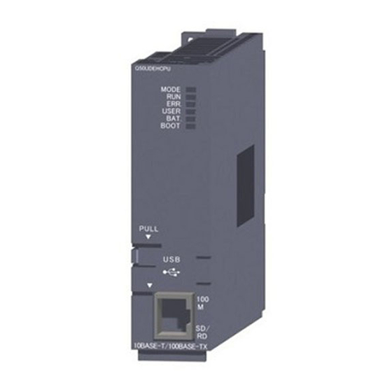
Page 110: Part Names
PRE-OPERATION PROCEDURES Part Names This section describes each part and its name of the EtherNet/IP module. QJ71EIP71 ERR. 10BASE-T/ 100BASE-TX 1), 2) QJ71EIP71 Figure 5.7 Part Names Table 5.2 Part name and description Name Description Indicates the operating status of the EtherNet/IP module. Indicator LED (1) LED indication in this section) Connects the EtherNet/IP module to 10BASE-T/100BASE-TX. - Page 111 PRE-OPERATION PROCEDURES (1) LED indication 10BASE-T/ 100BASE-TX QJ71EIP71 ERR. Figure 5.8 LED Table 5.3 LED indication Name LED status Description Module is operating normally. It may take time for the RUN LED to light when starting the system. Hardware fault or watchdog timer error Module stop error (Hardware error, IP Address not set, or others) Rapid flashing Module continuation error.
-
Page 112: Battery
PRE-OPERATION PROCEDURES Battery This section describes installation and replacement of the battery. 5.4.1 Battery specifications The specifications of the battery for the EtherNet/IP module are shown below. Table 5.4 Battery specifications Description Item Q6BAT Type Manganese dioxide lithium primary battery Initial voltage 3.0V Nominal current... -
Page 113: Detecting A Battery Error And Replacing The Battery
PRE-OPERATION PROCEDURES 5.4.3 Detecting a battery error and replacing the battery This section describes detection of a battery error and how to replace the battery of the EtherNet/IP module. When the battery voltage has dropped, the battery must be replaced. (1) Battery error detection of the EtherNet/IP module The battery of the EtherNet/IP module is used for error logging of the system. - Page 114 PRE-OPERATION PROCEDURES (3) Battery life (Q6BAT) (a) The table below shows the life of the EtherNet/IP module battery. Table 5.5 Battery life Battery life Power-on time Guaranteed value Actual usage value Guaranteed time ratio (MIN) (TYP) after a battery error 26000 hr 43800 hr 1500 hr...
- Page 115 PRE-OPERATION PROCEDURES (4) Replacement of the EtherNet/IP module battery At the end of battery life, replace the battery according to the procedure in Figure 5.11. Keep the programmable controller on at least 10 minutes before removing the battery. Replace the battery quickly even though the memory will be retained for a while after removal of the battery.
-
Page 116: Setting From Gx Works2
PRE-OPERATION PROCEDURES Setting from GX Works2 This section describes the GX Works2 settings required to operate the EtherNet/IP module. When using GX Developer, refer to the following. Appendix 3 When Using GX Developer 5.5.1 Intelligent function module detailed setting Set the Tag communication status for a CPU stop error. For details of Tag communication for a CPU stop error, refer to the following. -
Page 117: Switch Setting For The Intelligent Function Module
PRE-OPERATION PROCEDURES 5.5.2 Switch setting for the intelligent function module In the intelligent function module switch setting for the EtherNet/IP module, hardware test and self-loopback test can be set. No setting is required when not using the hardware test and self-loopback test. For details of the hardware and self-loop back test, refer to the following. - Page 118 PRE-OPERATION PROCEDURES POINT (1) Switch setting for I/O and intelligent function module takes effect when turning off and on the power or resetting the CPU module after execution of Write to PLC. (2) When the setting of "Switch Setting for I/O and Intelligent Function Module" is out of range, the ERR.
-
Page 119: Self-Diagnostics Of The Ethernet/Ip Module
PRE-OPERATION PROCEDURES Self-Diagnostics of the EtherNet/IP Module This section describes the self-diagnostics of the EtherNet/IP module. 5.6.1 Hardware test Hardware test checks the RAM and LEDs of the EtherNet/IP module. The hardware test procedure is shown below. (1) Setting the EtherNet/IP module 1) Set the CPU module switch to STOP. - Page 120 PRE-OPERATION PROCEDURES 2) For error completion, check the setting of "Switch Setting for I/O and Intelligent Function Module" and execute the self-loopback test again. 3) If the error is detected again, a hardware failure may have occurred in the EtherNet/IP module. Please consult your local Mitsubishi representative.
-
Page 121: Self-Loopback Test
PRE-OPERATION PROCEDURES 5.6.2 Self-loopback test It is a test to check the send/receive function of the EtherNet/IP module. The following is the procedure of a self-loopback test. (1) Setting the EtherNet/IP module 1) Set the CPU module switch to STOP. 2) Disconnect the twisted pair cable from the EtherNet/IP module. -
Page 122: Wiring
PRE-OPERATION PROCEDURES Wiring This section describes wiring of the EtherNet/IP module. (1) Components For details of the components, refer to the following. Section 2.2.2 Network components of the EtherNet/IP network (2) Wiring method Connect the EtherNet/IP module to a switching hub with a twisted pair cable. Switching hub EtherNet/IP module QJ71EIP71... -
Page 123: Wiring Precautions
PRE-OPERATION PROCEDURES 5.7.1 Wiring precautions Noise resistant wiring is one of the factors for the optimum performance of the EtherNet/IP module and highly reliable system operation. (1) Installation of 100BASE-TX and 10BASE-T Sufficient safety measures must be taken when installing 100BASE-TX or 10BASE-T cables. -
Page 124: Ping Test
PRE-OPERATION PROCEDURES PING Test This section describes the PING test. The PING test is used to check the existence of other devices on the same Ethernet (the same subnet address). (1) How to execute the PING test (a) From Utility Package 1) Double-click "Ping Test"... - Page 125 PRE-OPERATION PROCEDURES (b) From a sequence program The following is a program example in which a PING test is executed in a sequence program. In the example, a PING test is executed for IP address 192.168.0.2 when the start I/O No. of the EtherNet/IP module is set to "0000". PING test request flag Communication time check: 5 seconds...
-
Page 126: Chapter 6 Parameter
PARAMETER CHAPTER 6 PARAMETER This chapter describes parameters of the EtherNet/IP module. Parameter List and Setting Method (1) Parameter list and setting method 1) Set the following parameters. Table 6.1 Parameter list and setting method Reference PARAMETER Description Set from: section IP Address Set the IP address of the EtherNet/IP module. -
Page 127: Access To The Flash Rom
PARAMETER Access to the Flash ROM To keep parameters after turning off the programmable controller or resetting the CPU module, save them in the flash ROM. This section describes how to save or clear parameters in the flash ROM. (1) Program example The following is a program example of saving parameters in the flash ROM. -
Page 128: Chapter 7 Utility Package (Sw1Dnc-Eiputl-E)
UTILITY PACKAGE (SW1DNC-EIPUTL-E) CHAPTER 7 UTILITY PACKAGE (SW1DNC-EIPUTL-E) This chapter describes installing, uninstalling, functions, and usage of Utility Package. Remark For details of connection method and operating environment for Utility Package, refer to the following. Section 2.3 Operating Environment for Utility Package... -
Page 129: Precautions
UTILITY PACKAGE (SW1DNC-EIPUTL-E) Precautions (1) The number of auto refresh parameter settings (a) The number of auto refresh parameters that can be set to a QCPU When multiple intelligent function modules are mounted with, set parameters within the range shown in the table below. Table 7.1 Maximum number of auto refresh parameter settings Maximum number of auto CPU type... - Page 130 UTILITY PACKAGE (SW1DNC-EIPUTL-E) The setting for each tag is counted as one setting. Selection of "Not Use" is not included in the number of settings. Figure 7.2 How to count the number of auto refresh settings in "Tag Parameter" window POINT (1) When the number of auto refresh parameter settings exceeds the range of the QCPU...
-
Page 131: Installing And Uninstalling
UTILITY PACKAGE (SW1DNC-EIPUTL-E) Installing and Uninstalling 7.2.1 Installing This section describes how to install Utility Package. Check the following items before installation. POINT (1) Before installing, terminate all the running applications on Microsoft Windows . The installer may not function properly while the resident software such as update programs of the operating system or other manufacturers' software, such as Windows Update or Java, is automatically running. - Page 132 UTILITY PACKAGE (SW1DNC-EIPUTL-E) (Start) Start Windows Explorer and open the drive where the disk is loaded. Double-click "setup.exe". When using Windows Vista , the below window is displayed if User Account Control is enabled. Select "Allow". Double-click When using Windows 7, the below window is displayed if User Account Control is enabled.
- Page 133 UTILITY PACKAGE (SW1DNC-EIPUTL-E) (From the previous page) Click when the window shown on the left is displayed. Next Specify the folder where the file is installed and click Next When the below window is displayed on Windows Vista , click "Install this driver software anyway"...
- Page 134 UTILITY PACKAGE (SW1DNC-EIPUTL-E) (From the previous page) Clicking starts the installation. Install The installation is completed when the window shown on the left is displayed. Click the button. Finish (End) When an installation of Utility Package is successfully completed, icons will be created as shown below.
-
Page 135: Uninstalling
UTILITY PACKAGE (SW1DNC-EIPUTL-E) 7.2.2 Uninstalling This section describes how to uninstall Utility Package. POINT (1) When uninstalling, log on as a user with Administrator attributes. (2) Start uninstallation from the Control Panel on Windows . (3) Do not terminate the uninstallation while it's in process. If terminated, re-execute the uninstallation. - Page 136 UTILITY PACKAGE (SW1DNC-EIPUTL-E) (From the previous page) Select "SW1DNC-EIPUTL-E" and click Remove •For Windows Vista or Windows Select the program to delete in "Uninstall or change a program" and click "Uninstall". •When the below window is displayed on Windows Vista , click the button.
-
Page 137: Installing Usb Driver
UTILITY PACKAGE (SW1DNC-EIPUTL-E) 7.2.3 Installing USB driver Installation of USB driver is required for accessing to a QCPU via USB. The following is an installation procedure of USB driver. POINT When installation of USB driver is disabled, check the following settings. •... - Page 138 UTILITY PACKAGE (SW1DNC-EIPUTL-E) (1) For Windows The following is the installation procedure of USB driver on Windows (Start) Connecting a personal computer and QCPU with a USB cable displays the window shown on the left. Select "Install from a list or specific location [Advanced]" and click Next Select "Search for the best driver in these locations".
- Page 139 UTILITY PACKAGE (SW1DNC-EIPUTL-E) (2) For Windows Vista The following is the installation procedure of USB driver on Windows Vista . (Start) Connecting a personal computer and QCPU with a USB cable displays the window shown on the left. Select "Locate and install driver software (recommended)" and wait for the location.
- Page 140 UTILITY PACKAGE (SW1DNC-EIPUTL-E) (From the previous page) Click "Install this driver software anyway". Click the button. Close The installation is completed when the window shown on the left is displayed. Finish the installation by clicking Close (End) - 13 7.2 Installing and Uninstalling 7.2.3 Installing USB driver...
- Page 141 UTILITY PACKAGE (SW1DNC-EIPUTL-E) ® (3) For Windows ® The following is the installation procedure of USB driver on Windows (Start) Connecting a personal computer and QCPU with a USB cable displays the window shown on the left. Select [Start] [Control Panel] [Administrative Tools]. The window shown on the left appears.
- Page 142 UTILITY PACKAGE (SW1DNC-EIPUTL-E) (From the previous page) The window shown on the left appears. Specify "EZSocket\Easysocket\USBDrivers", where Utility Package has been installed, and click the button. Next The window shown on the left appears. Click the Install button. ...
-
Page 143: Operating Procedure
UTILITY PACKAGE (SW1DNC-EIPUTL-E) Operating Procedure The following flowchart shows how to create, edit and write a project to the system. Start Check box Start Utility package. Create a new project? Check box Section 7.7.2 Open the existing project. Section 7.7.1 Click [File] [New]. -
Page 144: Functions Of Utility Package
UTILITY PACKAGE (SW1DNC-EIPUTL-E) Functions of Utility Package 7.4.1 Function list of Utility Package The following table lists the functions of Utility Package. Table 7.3 Utility Package function list Function Description Reference section PING test Performs a PING test. Section 5.8 Exports label data that have been configured with Utility Package to a GX Section 7.8.1 Works2 project. -
Page 145: Window Structure
UTILITY PACKAGE (SW1DNC-EIPUTL-E) Window Structure This section describes the window structure of Utility Package. Switching tabs Menu bar Selection tree Figure 7.6 Window structure Table 7.4 Window structure Reference Function Description section Menu bar Any of the functions of Utility Package can be selected in the menu bar. Section 7.5.1 The EtherNet/IP module information that is registered in Utility Package (start I/O No. -
Page 146: Menus
UTILITY PACKAGE (SW1DNC-EIPUTL-E) 7.5.1 Menus (1) File menu Figure 7.7 File menu Table 7.5 Description of the file menu Reference Item Description section The following procedure shows how to create a new project. Section 7.7.1 Open Finds and opens an existing project. Section 7.7.2 Save Overwrites and saves the project. -
Page 147: How To Use The Selection Tree
UTILITY PACKAGE (SW1DNC-EIPUTL-E) 7.5.2 How to use the selection tree The EtherNet/IP module information that has been configured in Utility Package (start I/O No. and IP address) is displayed. Also, settings common to all modules are configured and a PING test is conducted. The operations of the selection tree are listed in the following table. -
Page 148: Main" Tab (Module Status Display)
UTILITY PACKAGE (SW1DNC-EIPUTL-E) "Main" Tab (Module Status Display) The connection status of the modules is displayed. Figure 7.11 "Main" tab Table 7.9 "Main" tab items Item Description Start Monitoring The monitoring on the "Main" tab is started or stopped. Stop Monitoring [Monitoring] button The monitoring status is displayed. - Page 149 UTILITY PACKAGE (SW1DNC-EIPUTL-E) Table 7.9 "Main" tab items Item Description Nic No Nic1/Nic2/Nic3/Nic4 is displayed. The latest error code that occurred at the own station is displayed. ( Section 9.4.2 Error code [Module Error Error Code list) Information] Description The details of the existing errors are displayed. Action The corrective actions for the existing errors are displayed.
- Page 150 UTILITY PACKAGE (SW1DNC-EIPUTL-E) (1) "Detail View" window Clicking the button will display the window below. Detail View Figure 7.12 "Detail View" window Table 7.10 "Detail View" window items Item Description The Tag names assigned to Nic1 to 4 by Tag type (Producer/Consumer/UCMM/Class3) and the communication status below are displayed.
-
Page 151: Project File
UTILITY PACKAGE (SW1DNC-EIPUTL-E) Project File This section describes how to operate project files. 7.7.1 Creating a new project The following procedure shows how to create a new project. 1) Click [File] [New]. The "Main" tab is displayed. 2) Clicking the "Setting" tab will display the "Basic" window below. Make settings for [Own Nic], referring to the explanations below. -
Page 152: Opening A Project
UTILITY PACKAGE (SW1DNC-EIPUTL-E) 7.7.2 Opening a project The following shows how to find and open an existing project. 1) Click [File] [Open]. The "Open" window is displayed. 2) Select the items listed in the Table 7.11 and click Open Figure 7.14 "Open" window Table 7.11 Setting items in the "Open"... -
Page 153: Saving A Project
UTILITY PACKAGE (SW1DNC-EIPUTL-E) 7.7.3 Saving a project The following shows how to save a project. (1) Saving a project Click [File] [Save]. (2) Saving a project with a different name Click [File] [Save As]. The "Save As" window is displayed. Set the items listed in the Table 7.12 and click Save Figure 7.15 "Save As"... -
Page 154: Exporting Setting Data
UTILITY PACKAGE (SW1DNC-EIPUTL-E) Exporting Setting Data Label data for GX Works2 configured with Utility Package can be exported to GX Works2. Section 7.8.1) The following can also be executed with Utility Package. • Exporting Tag Parameters (CSV files) ( Section 7.8.2) Utility package GX Works2 (label) Export... -
Page 155: Exporting Label Data For Gx Works2
UTILITY PACKAGE (SW1DNC-EIPUTL-E) 7.8.1 Exporting label data for GX Works2 Export the label data that have been configured with Utility Package to a GX Works2 project. The label names that have been configured with Utility Package can be used in the programming of GX Works2. - Page 156 UTILITY PACKAGE (SW1DNC-EIPUTL-E) (2) Precautions (a) Label names • Up to 32 characters can be used for a label name. • Case-sensitive label names cannot be used. (Label names are not case- sensitive.) • Names of tasks, structures, and program parts cannot be used as label names.
-
Page 157: Exporting Tag Parameter
UTILITY PACKAGE (SW1DNC-EIPUTL-E) 7.8.2 Exporting Tag Parameter The following shows how to export Tag Parameter set in Utility Package to a CSV file. (1) Exporting 1) Click [File] [Export] [Class1 Tag] or [Class3/UCMM] The "SaveAs" window is displayed. 2) Set the items listed in the Table 7.13 and click Save Figure 7.18 "SaveAs"... -
Page 158: Setting" Tab (Parameter Settings)
UTILITY PACKAGE (SW1DNC-EIPUTL-E) "Setting" Tab (Parameter Settings) This section describes the "Setting" tab where the EtherNet/IP module is configured. When multiple EtherNet/IP modules are connected to one CPU module, settings can be performed simultaneously for four modules per project. When making the settings, first add the information of the EtherNet/IP module under "[Own Nic]"... - Page 159 UTILITY PACKAGE (SW1DNC-EIPUTL-E) Table 7.14 "Basic" window settings Item Description Add the EtherNet/IP module information to the project and edit it. [Own Nic] Double-click the cell to add and edit the information. ( (1) Display and settings of the "Add Own Nic" window in this section) The numbers for distinguishing the settings by module are displayed.
- Page 160 UTILITY PACKAGE (SW1DNC-EIPUTL-E) (1) Display and settings of the "Add Own Nic" window Figure 7.21 "Add Own Nic" window Table 7.15 "Add Own Nic" window items Item Description Start I/O No. Set the start I/O No. of the EtherNet/IP module. (Hexadecimal) Nic Name Set the name of the EtherNet/IP module.
- Page 161 UTILITY PACKAGE (SW1DNC-EIPUTL-E) Table 7.15 "Add Own Nic" window items (Continued) Item Description Common Parameter Set the number of connection tags and the size of the storage area for transmitted and received data. When using a tag name with 41 or more characters in various tag setting windows, select the checkbox. Extension Tag Name Setting The availability of a tag name with 41 or more characters differs depending on the version of the Enable...
- Page 162 UTILITY PACKAGE (SW1DNC-EIPUTL-E) Table 7.15 "Add Own Nic" window items (Continued) Item Description Input/ Set the total of the extended sizes of Class1 Input Area and Class1 Output Area. Output Default setting: 8192 words Area Size Maximum data size: 16384 words Set the extended size of Class1 Input Area.
-
Page 163: Producer" Window
UTILITY PACKAGE (SW1DNC-EIPUTL-E) 7.9.2 "Producer" window Make settings for the Producer Tag and the auto refresh target device of the Class1 Tag communications. (1) Display and settings of the "Producer" window Tag setting status list Tag Parameter list Figure 7.22 "Producer" window Table 7.16 "Producer"... - Page 164 UTILITY PACKAGE (SW1DNC-EIPUTL-E) Table 7.16 "Producer" window items (Continued) Item Description The parameters set in the "Producer Tag" window are displayed. ( (2) Display and settings of the Tag Parameter list "Producer Tag" window in this section) Nic No. Tag Name The parameters set in the "Producer Tag"...
- Page 165 UTILITY PACKAGE (SW1DNC-EIPUTL-E) (2) Display and settings of the "Producer Tag" window Figure 7.23 "Producer Tag" window Table 7.17 "Producer Tag" window settings Item Description Select an Own Nic No. Set the Tag name. Tag Name Up to 100 one-byte alphanumeric characters can be used. (Up to 32 alphanumeric characters when using a label) When the "Label (for GX Works2) Setting Enable"...
- Page 166 UTILITY PACKAGE (SW1DNC-EIPUTL-E) Table 7.17 "Producer Tag" window settings (Continued) Item Description The refresh device can be set with "Device" when the checkbox is selected. Refresh Device When auto refresh settings are made in the "Refresh Parameter" window, the settings made here are disabled. When using the auto refresh function, set the refresh target device and the start number of the device.
-
Page 167: Consumer" Window
UTILITY PACKAGE (SW1DNC-EIPUTL-E) 7.9.3 "Consumer" window Make settings for the Consumer Tag and the auto refresh target device of the Class1 Tag communications. (1) Display and settings of the "Consumer" window Tag setting status list Tag Parameter list Figure 7.24 "Consumer" window Table 7.18 "Consumer"... - Page 168 UTILITY PACKAGE (SW1DNC-EIPUTL-E) Table 7.18 "Consumer" window items (Continued) Item Description The parameters set in the "Consumer Tag" window are displayed. ( (2) Display and settings of the Tag Parameter list "Producer Tag" window in this section) Nic No. Tag Name Size(INT) Connection Type The parameters set in the "Consumer Tag"...
- Page 169 UTILITY PACKAGE (SW1DNC-EIPUTL-E) (2) Display and settings of the "Consumer Tag" window Figure 7.25 "Consumer Tag" window Table 7.19 "Consumer Tag" window settings Item Description Select an Own Nic No. Set the tag name. Tag Name Up to 100 one-byte alphanumeric characters can be used. (Up to 32 alphanumeric characters when using a label) When the "Label (for GX Works2) Setting Enable"...
- Page 170 UTILITY PACKAGE (SW1DNC-EIPUTL-E) Table 7.19 "Consumer Tag" window settings (Continued) Item Description Set the Producer Tag name of the communication destination. Remote Tag Up to 100 one-byte alphanumeric characters can be used. (Up to 32 alphanumeric characters when using a label) Set the conditions for Class1 Tag communications.
-
Page 171: Message" Window
UTILITY PACKAGE (SW1DNC-EIPUTL-E) 7.9.4 "Message" window Make settings for the Class3/UCMM Tag and the auto refresh target Tag. (1) Display and settings of the "Message" window Tag setting status list Tag Parameter list Figure 7.26 "Message" window Table 7.20 "Message" window items Item Description The settings of the Class3/UCMM Tag communications are displayed. - Page 172 UTILITY PACKAGE (SW1DNC-EIPUTL-E) Table 7.20 "Message" window items (Continued) Item Description The parameters set in the "Message Tag" window are displayed. ( (2) Display and settings of the Tag Parameter list "Message Tag" window in this section) Nic No. Tag Name Size(INT) Connection Type The parameters set in the "Message Tag"...
- Page 173 UTILITY PACKAGE (SW1DNC-EIPUTL-E) (2) Display and settings of the "Message Tag" window Figure 7.27 "Message Tag" window Table 7.21 "Message Tag" window settings Item Description Select an Own Nic No. Connection Type Select "Class3" or "UCMM". Select the Class3/UCMM Tag communications type. •"Originator Read": Requests reading to the Tag of the connected device.
- Page 174 UTILITY PACKAGE (SW1DNC-EIPUTL-E) Table 7.21 "Message Tag" window settings (Continued) Item Description Set the waiting time for a response to a request from the connected device when selecting "Originator Read" or Timeout "Originator Write" in "Setting Type". Setting range: 30 to 10000 (Default: 30) Set the conditions for Class3/UCMM Tag communications when selecting "Originator Read"...
-
Page 175: User Define" Window
UTILITY PACKAGE (SW1DNC-EIPUTL-E) 7.9.5 "User Define" window Arbitrarily define Data Types other than INT and DINT and register them. (1) Display and settings of the "User Define" window List box Text box Define list Figure 7.28 "User Define" window Table 7.22 "User Define" window items Item Description Register Data Types in addition to the predefined Data Types (INT and DINT). - Page 176 UTILITY PACKAGE (SW1DNC-EIPUTL-E) Table 7.22 "User Define" window items (Continued) Item Description Define definition (element that configures the Data Type) in the registered Data Type. A Name Among The User Define List (Size) Up to 256 Defines can be registered per Data Type. A number is assigned and displayed every time a Define is added.
-
Page 177: Rpi Set" Window
UTILITY PACKAGE (SW1DNC-EIPUTL-E) 7.9.6 "RPI Set" window Use this window when configuring RPI (Request Packet Interval) of all Tags collectively. This window is displayed when "RPI Set" in the selection tree is double-clicked. (1) Display and settings of the "RPI Set" window Figure 7.29 "RPI Set"... -
Page 178: Refresh Parameter" Window
UTILITY PACKAGE (SW1DNC-EIPUTL-E) 7.9.7 "Refresh Parameter" window Set the refresh target device of the items below for each EtherNet/IP module. • Send/receive data of Tag communication • Error codes of own station • Communication status of Class1 or Class3/UCMM Tag communication •... - Page 179 UTILITY PACKAGE (SW1DNC-EIPUTL-E) Table 7.24 Description of the "Refresh Parameter" window Item Description Displays the data items to refresh. (Data Area) Set the refresh target device for send/receive data of Tag communication for each input/output area. The following are setting items and their buffer memory. Setting Area •Class1 Input Area (Un\G0 to Un\G4095) •Class3/UCMM Input Area (Un\G4096 to Un\G8191)
- Page 180 UTILITY PACKAGE (SW1DNC-EIPUTL-E) (4) Refreshing send/receive data of Tag communication Setting is available in either way of the following. Table 7.25 Send/receive data of Tag communication refreshing Setting the refresh target Description Setting window device Refresh target device can be set for each tag. The refresh target devices can be kept unchanged even when Tag Parameter is added or deleted.
-
Page 181: Online
UTILITY PACKAGE (SW1DNC-EIPUTL-E) 7.10 Online This section describes the online operations of the EtherNet/IP module connected in a network. 7.10.1 Configuring the EtherNet/IP module Configure the EtherNet/IP module in connection destination. (1) Displaying the "Transfer Setup" window Click [Online] [Transfer Setup]. (2) "Transfer Setup"... - Page 182 UTILITY PACKAGE (SW1DNC-EIPUTL-E) Table 7.26 Description of the "Transfer Setup" window Reference Item Description section PLC Type Select the model name of the QCPU. Clicking the button will display the "PC side I/F Setting" window. PC I/F Setup Select the connection interface type. The following settings must be made when "RS-232C"...
-
Page 183: Writing Parameters To The Ethernet/Ip Module
UTILITY PACKAGE (SW1DNC-EIPUTL-E) 7.10.2 Writing parameters to the EtherNet/IP module Write the set parameters to the EtherNet/IP module. (1) Displaying the "Download Parameter" window Click [Online] [Download Parameter]. "Transfer Setup" window will be displayed if the above operation is performed without setting the connected EtherNet/IP module. - Page 184 UTILITY PACKAGE (SW1DNC-EIPUTL-E) Table 7.27 Description of the "Download Parameter" window (Continued) Reference Item Description section Writes the parameters to the EtherNet/IP module. Item Description All checkboxes are selected. button All Select All checkboxes are cleared. button Clear When they are selected, the settings made in the Refresh Parameter "Refresh Parameter"...
- Page 185 UTILITY PACKAGE (SW1DNC-EIPUTL-E) (3) Precautions (a) Perform either of the operation below when writing intelligent function module parameters other than those of the EtherNet/IP module to a QCPU through GX Works2. • After writing auto refresh parameters in Utility Package, read the intelligent function module parameters by "Read form PLC"...
-
Page 186: Reading Out Parameters Of The Ethernet/Ip Module
UTILITY PACKAGE (SW1DNC-EIPUTL-E) 7.10.3 Reading out parameters of the EtherNet/IP module Reads out the parameters of the EtherNet/IP module. (1) Displaying the "Upload Parameter" window Click [Online] [Upload Parameter]. "Transfer Setup" window will be displayed if the above operation is performed without setting the connected EtherNet/IP module. - Page 187 UTILITY PACKAGE (SW1DNC-EIPUTL-E) Table 7.28 Description of the "Upload Parameter" window (Continued) Reference Item Description section Reads out the parameters of the EtherNet/IP module. Item Description All checkboxes are selected. button All Select All checkboxes are cleared. button Clear When they are selected, the settings made in the Refresh Parameter "Refresh Parameter"...
-
Page 188: Monitoring" Tab (Network Diagnostics)
UTILITY PACKAGE (SW1DNC-EIPUTL-E) 7.11 "Monitoring" tab (Network Diagnostics) The following table shows functions of Network diagnostics. Table 7.29 "Monitoring" tab items Function Reference points Section 7.11 (1) "Producer" window The Producer Tag status can be monitored. Section 3.3.14 Communication status (Class1) Section 7.11 (2) "Consumer"... - Page 189 UTILITY PACKAGE (SW1DNC-EIPUTL-E) (1) "Producer" window Figure 7.35 "Producer" window Table 7.30 "Producer" window items Item Description Monitoring is started or stopped in the "Producer" window. button Start Monitoring Stop Monitoring The monitoring status is displayed. Monitoring/Stop •"Monitoring ● (green)": Monitoring •"Stop ●...
- Page 190 UTILITY PACKAGE (SW1DNC-EIPUTL-E) (2) "Consumer" window Figure 7.36 "Consumer" window Table 7.31 "Consumer" window items Item Description Monitoring is started or stopped in the "Consumer" window. button Start Monitoring Stop Monitoring The monitoring status is displayed. Monitoring/Stop •"Monitoring ● (green)": Monitoring •"Stop ●...
- Page 191 UTILITY PACKAGE (SW1DNC-EIPUTL-E) Table 7.31 "Consumer" window items (Continued) Item Description Select the display format of "Tag Data View". •When ASCII is selected, data except 20 to 7F are displayed as ".". When the selected Tag is of the Data Type that has been registered in the "User Define" window, HEX/DEC/BIN/ASCII/ data are displayed as the configured Data Type.
- Page 192 UTILITY PACKAGE (SW1DNC-EIPUTL-E) (3) "Message" window Figure 7.37 "Message" window Table 7.32 "Message" window items Item Description Monitoring is started or stopped in the "Message" window. button Start Monitoring Stop Monitoring The monitoring status is displayed. •"Monitoring ● (green)": Monitoring Monitoring/Stop •"Stop ●...
- Page 193 UTILITY PACKAGE (SW1DNC-EIPUTL-E) (4) "Connection" window Figure 7.38 "Connection" window Table 7.33 "Connection" window items Item Description Monitoring is started or stopped in the "Connection" window. button Stop Monitoring Stop Monitoring The monitoring status is displayed. •"Monitoring ● (green)": Monitoring Monitoring/Stop •"Stop ●...
- Page 194 UTILITY PACKAGE (SW1DNC-EIPUTL-E) Table 7.33 "Connection" window items Item Description The details of the Producer Tag/Message Tag that have been registered in the EtherNet/IP module Producer List are displayed. TAG TYPE The type of the Tag (Class1/Class3/UCMM) is displayed. TAG SIZE The size of the Tag is displayed in INT units.
-
Page 195: Help Menu
UTILITY PACKAGE (SW1DNC-EIPUTL-E) 7.12 Help Menu The product information of Utility Package is displayed on this window. (1) Displaying the version information window Click [About] from [Help] menu. (2) Version information on the "About" window Figure 7.39 Version information on the "About" window 7.12 Help Menu - 68... -
Page 196: Chapter 8 Programming
PROGRAMMING CHAPTER 8 PROGRAMMING This chapter describes programming of the EtherNet/IP module. System Configuration Example This section describes the system configuration. In and after Section 8.2, the following system structure is used for explanation. System 2 IP address: 192.168.0.2 System 1 IP address: 192.168.0.1 Switching GX Works2... - Page 197 PROGRAMMING (b) Tag name Consider a tag name for Producer Tag. The names for Consumer Tag and Producer Tag must be matched. Table 8.1 Considering tag names for Class1 Tag communication Producer Tag Tag name Producer Tag (8 words) System1_Data1 192.168.0.1 Producer Tag (12 words) System1_Data2...
-
Page 198: Parameter Setting
PROGRAMMING Parameter Setting Set parameters in Utility Package referring to Section 8.1 and Section 8.2 and write them to the module. (1) System 1 (192.168.0.1) setting (a) IP address and Common Parameter setting Double-click a cell in "Own Nic" in the "Basic" window on the "Setting" tab and make settings in the "Add Own Nic"... - Page 199 PROGRAMMING (c) Class1 Tag Parameter setting Make settings in the "Producer" window on the "Setting" tab as shown below. Figure 8.6 Setting in the "Producer" window for System 1 Make settings in the "Consumer" window on the "Setting" tab as shown below. Figure 8.7 Setting in the "Consumer"...
- Page 200 PROGRAMMING (d) Class3/UCMM Tag Parameter setting Make settings in the "Message" window on the "Setting" tab as shown below. Figure 8.9 Setting in the "Message" window for System 1 Set the items not displayed in the above Tag Parameter list as shown below. Figure 8.10 Setting in the "Message Tag"...
- Page 201 PROGRAMMING (2) System 2 (192.168.0.2) setting Use the default settings except for the following settings. (a) IP address and Common Parameter setting Make settings in the "Add Own Nic" window as shown below. Figure 8.11 Setting in the "Add Own Nic" window for System 2 (b) Connected device setting Make settings in "[Remote Nic]"...
- Page 202 PROGRAMMING (c) Class1 Tag Parameter setting Figure 8.13 Class1 Tag Parameter setting for System 2 Set the items not displayed in the above Tag Parameter list to the same values as those of System 1 (192.168.0.1). ( (1) (c) Class1 Tag Parameter setting in this section) (d) Class3/UCMM Tag Parameter setting Figure 8.14 Class3/UCMM Tag Parameter setting for System 2...
- Page 203 PROGRAMMING (3) System 3 (192.168.0.3) setting Use the default settings except for the following settings. (a) IP address and Common Parameter setting Make settings in the "Add Own Nic" window as shown below. Figure 8.15 Setting in the "Add Own Nic" window for System 3 (b) Connected device setting Make settings in "[Remote Nic]"...
- Page 204 PROGRAMMING (c) Class1 Tag Parameter setting Figure 8.17 Class1 Tag Parameter setting for System 3 Set the items not displayed in the above Tag Parameter list to the same values as those of System 1 (192.168.0.1). ( (1) (c) Class1 Tag Parameter setting in this section) (d) Class3/UCMM Tag Parameter setting Figure 8.18 Class3/UCMM Tag Parameter setting for 192.168.0.3...
-
Page 205: Program Example
PROGRAMMING Program Example This section describes program examples. The list below shows the devices used for program examples in and after Section 8.4.1. (1) I/O signals of the EtherNet/IP module Table 8.3 I/O signals of the EtherNet/IP module Device Application Device Application Tag communication start process completion... - Page 206 PROGRAMMING Table 8.5 Devices used by user (Continued) Device Application Device Application Indirectly specified device for Application Trigger Indirectly specified device for the refresh target acceptance of receive data Indirectly specified device for Application Trigger Indirectly specified device for the number of tags completion Indirectly specified device for communication Indirectly specified device for Tag No.
-
Page 207: Program Example Of Tag Communication
PROGRAMMING 8.4.1 Program example of Tag communication This section shows examples of Tag communication programs in System 1 (192.168.0.1). (1) Setting auto refresh When using auto refresh, complete the following settings in Utility Package. (a) Class1 Tag parameter setting Set the auto refresh target device Set the auto refresh target device Figure 8.19 Class1 Tag Parameter setting for System 1 (b) Class3/UCMM Tag parameter setting... - Page 208 PROGRAMMING (c) Refresh parameter setting Figure 8.21 Refresh Parameter setting for System 1 - 13 8.4 Program Example 8.4.1 Program example of Tag communication...
-
Page 209
PROGRAMMING (2) Program Example Write the following sequence program to the QCPU set at 192.168.0.1. A part enclosed with a dotted line is not required when auto refresh is set in Utility Package.
Index register initialization Class1 Tag Counts acquisition Refresh data set for all Tags. - Page 210 PROGRAMMING < Initial setting at startup > Indirect specification for Application Trigger acceptance Indirect specification for Application Trigger completion < Tag communication start > Set Tag communication start request (Y00) to ON. < Error handling > Processing for own station error For own station error Processing for Class1 Tag No.1 error...
- Page 211 PROGRAMMING Processing for Class3/UCMM Tag No.3 error For Class3/UCMM Tag No.3 error Processing for Class3/UCMM Tag No.4 error For Class3/UCMM Tag No.4 error Processing for Class3/UCMM Tag No.5 error For Class3/UCMM Tag No.5 error Processing for Class3/UCMM Tag No.6 error For Class3/UCMM Tag No.6 error <...
- Page 212 PROGRAMMING < Data transmission > Processing for Class1 Tag No.1 data transmission For Class1 Tag No.1 data transmission (Cyclic) (Cyclic) Processing for Class1 Tag No.1 data transmission (Application Trigger) < Application Trigger request ON > For Class1 Tag No.1 data transmission <...
-
Page 213
PROGRAMMING A part enclosed with a dotted line is not required when auto refresh is set in Utility package.
Index register initialization Class1 Tag Counts acquisition Refresh data set for all Tags. (FOR to NEXT) Class1 send data start address acquisition Data size acquisition Store send data in Output Area. -
Page 214: Chapter 9 Troubleshooting
TROUBLESHOOTING CHAPTER 9 TROUBLESHOOTING This chapter describes how to troubleshoot the EtherNet/IP module and error codes. Troubleshooting Procedure This section describes troubleshooting procedure. The following shows troubleshooting procedure in a flowchart. (1) Before troubleshooting Confirm that there is no error in the CPU module. If any error is identified in the CPU module, check the detail and take corrective actions. -
Page 215: Checking Errors By The Led And Corrective Actions
TROUBLESHOOTING Checking Errors by the LED and Corrective Actions This chapter describes how to check errors on the LED. (1) Causes and actions The following table shows possible causes indicated by the LED status of the EtherNet/IP module and corrective actions. Table 9.1 Checking errors by the LED and corrective actions LED status Cause... -
Page 216: When Tag Communication Is Disabled
TROUBLESHOOTING When Tag Communication is Disabled The following flowchart shows the troubleshooting when the Tag communication is disabled. Start Check box Erase the setting for Switch 1 in intelligent Setting function module switch setting. Any value set for Switch 1 exists. -
Page 217: When The Err.led Is Off
TROUBLESHOOTING 9.3.2 When the ERR.LED is off Any of the following is the possible cause. • Tag communication is not started • Tag communication is on but never communicated • An error message was returned in Class3 or UCMM Tag communication Start Check box Connect the cable with the EtherNet/IP module... - Page 218 TROUBLESHOOTING (1) For Class1 Tag communication Start Check box Check if the Tag is communicating normally. Section 7.11 "Monitoring" tab (Network Diagnostics) Section 5.8 PING Test Is the Tag communicating normally? If the PING test failed, check that the IP addresses of the EtherNet/IP module and other devices are correct.
- Page 219 TROUBLESHOOTING (2) For Class3 Tag communication Start Check box Check if the Tag is communicating normally. Section 7.11 "Monitoring" tab (Network Diagnostics) Turn off the Tag communication start request (Y00) and then execute a PING test. Section 5.8 PING Test Is the Tag communicating normally? If the PING test failed, check that the IP addresses of the EtherNet/IP module and other devices are correct.
- Page 220 TROUBLESHOOTING (3) For UCMM Tag communication Start Turning on the Tag's Application Trigger request Check box (Class3/UCMM) (Un\G27072 to Un\G27087) sends the Was the Application Trigger request. request (Class3/UCMM) (Un\G27072 to Section 3.3.12 Application Trigger Un\G27087) turned on? (Class3/UCMM) Turned on Check the Communication Error (Class3/UCMM) (Un\G27200 to Un\G27215) for a response error.
-
Page 221: Error Code
TROUBLESHOOTING Error Code This section describes error codes of the EtherNet/IP module and how to retrieve them. 9.4.1 How to check error codes The following describes how to check error codes. (1) Checking in Utility Package Error codes can be checked in Utility Package. (a) Error codes of the EtherNet/IP module Check error codes displayed in "Module Error Information"... - Page 222 TROUBLESHOOTING (2) Checking by operating status Error codes are stored or displayed in the following location. Table 9.2 Classification and storage location of error codes Error code Reference Errors occur when; Stored in /displayed on (Hex.) section 0400 Section 9.4.2 (1) Ping test Execution result (Un\G27908) C400...
-
Page 223: Error Code List
TROUBLESHOOTING 9.4.2 Error code list The following table shows error codes of the EtherNet/IP module. (1) PING test status (Normal) Table 9.3 PING test status (Normal) Error code Error Error detail Action (Hex.) 0400 - (Normal) The PING test completed normally (2) Self-diagnostics status (Normal) Table 9.4 Self-diagnostics status (Normal) Error code... - Page 224 TROUBLESHOOTING Table 9.5 Parameter error of the EtherNet/IP module (Error) (Continued) Error code Error Error detail Action (Hex.) Check the error details by any of the following and correct the Tag Parameter. •"Detail View" window on the "Main" tab in Utility Tag Parameter Package C011...
- Page 225 TROUBLESHOOTING (4) Communication error of the EtherNet/IP module Table 9.6 Communication error of the EtherNet/IP module Error code Error Error detail Action (Hex.) TX FIFO underflow •Increase the RPI value in Consumer Tag and C100 A TX FIFO underflow error occurred. error restart the Tag communication.
- Page 226 TROUBLESHOOTING Table 9.6 Communication error of the EtherNet/IP module (Continued) Error code Error Error detail Action (Hex.) Connection establishment failed. C120 Connection failure The target device is offline. Connection establishment failed. •Check if the target device is operating normally. C121 Connection failure The target device is online, but not respond to a •Check if the line status is normal...
- Page 227 TROUBLESHOOTING Table 9.6 Communication error of the EtherNet/IP module (Continued) Error code Error Error detail Action (Hex.) C137 Please consult your local Mitsubishi System error System error C138 representative. Connection There is no connection information available for •Retry after a while. C139 information the specified instance.
- Page 228 TROUBLESHOOTING Table 9.6 Communication error of the EtherNet/IP module (Continued) Error code Error Error detail Action (Hex.) The specified RPI (Max) value is outside the C175 Invalid Max_RPI Correct the "Max RPI" value in Producer Tag. range of 6 to 10000. C176 Please consult your local Mitsubishi System error...
- Page 229 TROUBLESHOOTING Table 9.6 Communication error of the EtherNet/IP module (Continued) Error code Error Error detail Action (Hex.) Tag communication is attempted to the target specified by invalid Tag Parameter data. C194 The target device does not support the specified connection type, connection priority, redundancy owner, or size fixed/variable connection.
- Page 230 TROUBLESHOOTING Table 9.6 Communication error of the EtherNet/IP module (Continued) Error code Error Error detail Action (Hex.) Connection timed out. Find the conditions for the target device to notify A client attempted to send a connection-oriented this error and take measures. C1A1 message (Class1 or Class3 Tag communication) the manual for the target device)
- Page 231 TROUBLESHOOTING Table 9.6 Communication error of the EtherNet/IP module (Continued) Error code Error Error detail Action (Hex.) No port is available. C1AC The port specified in the port segment is not Find the conditions for the target device to notify available or does not exist.
- Page 232 TROUBLESHOOTING Table 9.6 Communication error of the EtherNet/IP module (Continued) Error code Error Error detail Action (Hex.) Redundant connection mismatch. The following fields do not match when attempting to establish a redundant owner connection to the same target path. •O T_RPI C1B6 •O...
- Page 233 TROUBLESHOOTING (5) Own station error of the EtherNet/IP module Table 9.7 Own station error of the EtherNet/IP module Error code Error Error detail Action (Hex.) Turn off the following signals before turning on the Tag communication Tag communication start request (Y00). An error was detected in the execution conditions start request (Y00) •PING test execution request (Y02)
- Page 234 TROUBLESHOOTING (7) Errors of self-diagnostics (Error) Table 9.9 Errors of self-diagnostics (Error) Error code Error Error detail Action (Hex.) 2-port RAM test An error was detected in the 2-port RAM test of C500 error the hardware test. Sam check test An error was detected on the sum check test of C501 error...
-
Page 235: Appendices
APPENDICES APPENDICES Appendix 1 Transportation Precautions When transporting lithium batteries, treat them based on the transportation regulations. Appendix 1.1 Controlled model The lithium battery for the EtherNet/IP module is classified as follows. Table APPX.1 Lithium battery Classification for Product Name Model Name Product supply status transportation... -
Page 236: Appendix 2 Handling Of Batteries And Devices With Built-In Batteries In Eu Member States
APPENDICES Appendix 2 Handling of Batteries and Devices with Built-in Batteries in EU Member States This section describes the precautions for disposing of waste batteries in EU member states and exporting batteries and/or devices with built-in batteries to EU member states. Appendix 2.1 Disposal precautions In EU member states, there is a separate collection system for waste batteries. -
Page 237: Appendix 2.2 Exportation Precautions
APPENDICES Appendix 2.2 Exportation precautions The new EU Battery Directive (2006/66/EC) requires the following when marketing or exporting batteries and/or devices with built-in batteries to EU member states. • To print the symbol on batteries, devices, or their packaging. • To explain the symbol in the manuals of the products (1) Labeling To market or export batteries and/or devices with built-in batteries, which have no symbol, to EU member states on September 26, 2008 or later, print the symbol shown... -
Page 238: Appendix 3 When Using Gx Developer
APPENDICES Appendix 3 When Using GX Developer This section describes the operating procedure when using GX Developer. (1) Applicable software version For the applicable software version, refer to the following. Section 2.1 (3) Applicable software packages Appendix 3.1 Operation of GX Developer Configure the following settings when using GX Developer. - Page 239 APPENDICES (2) Switch setting for the intelligent function module Double-click "PLC parameter" in the project window and click the "I/O assignment" tab. Figure APPX.4 "I/O assignment" Clicking displays the "Switch setting for I/O and intelligent function Switch setting module" window. Refer to the following and complete the setting.
-
Page 240: Appendix 4 Calculation For The Total Size Of Character String Information Parameters
APPENDICES Appendix 4 Calculation for the Total Size of Character String Information Parameters Set the total size of the character string information parameters (Nic Name, Node Name, Tag name, Data Type name, and Define name) as follows. • 32K words or less for one module (Own Nic) •... -
Page 241: Appendix 4.2 Example Of The Character String Information Parameter Setting
APPENDICES Appendix 4.2 Example of the character string information parameter setting This section describes examples of the character string information parameter setting. Examples of calculation for character string information parameters are described in Appendix 4.3. (1) Setting in the "Basic" window Table APPX.6 Setting in "[Own Nic]"... - Page 242 APPENDICES (4) Setting in the "Message" window (only data related to character string information parameters) When "Setting Type" is "Target Read" or "Target Write", the Tag name does not affect the size of character string information parameters. Table APPX.10 Setting in the "Message" window (abstract) Data Remote Tag Tag name...
- Page 243 APPENDICES Appendix 4.3 Examples of calculation for character string information parameters This section describes examples of calculation for the total size of character string information parameters using the setting examples described in Appendix 4.2. (1) Total size of character string information parameters used in Nic No. 1 (a) Nic Name Nic Name = 14 characters ("MY_NIC_NAME_01") NicName+1...
- Page 244 APPENDICES (2) Total size of character string information parameters used in Nic No. 2 (a) Nic Name Nic Name = 14 characters ("MY_NIC_NAME_02") NicName+1 +1=8 (b) Node Name n = 4, m = 4 REMCON = 13 characters ("NODE_NIC2_001") REMCON = Excluded from calculation because Node Name is the same as that of REMCON REMCON...
- Page 245 APPENDICES (d) Data Type name, Define name n = 0 UDi+1 +TOTALDLi+512=0+0+512=512 According to (a) to (d), the total size of character string information parameters used in Nic No. 2 is obtained by: Header + Nic Name + Node Name + Tag name + Data Type name, Define name + Footer = 9+8+528+560+512+1 =1618 words.
-
Page 246: Appendix 4.3 Examples Of Calculation For Character String Information Parameters
APPENDICES (d) Data Type name, Define name n = 4 = Data Type name used in "CS_03_001" = 6 characters ("UD_100) = Data Type name used in "CS_03_002" = 6 characters ("UD_200) = Data Type name used in MAR_03_001 = Excluded from calculation because the Data Type name is the same as that of UD = Data Type name used in UAW_03_001 = Excluded from calculation because the Data Type name is the same as that of UD... - Page 247 APPENDICES (5) Grand total In the case of the setting examples described in Appendix 7.2, the grand total size of character string information parameters is obtained by summing up the sizes used in Nic Nos. 1 to 4: 1619+1618+1700+1700 = 6637 words. APPX Appendix 4 Calculation for the Total Size of Character String Information Parameters - 13...
-
Page 248: Appendix 5 Added And Enhanced Functions
APPENDICES Appendix 5 Added and enhanced Functions The following table lists the added and enhanced functions in the EtherNet/IP module. Table APPX.13 Function added and supported Utility Package version Added and enhanced functions Serial No. (first 5 digits) Utility package version Setting of a tag name with 41 or more characters "17012"... - Page 249 APPENDICES Memo APPX Appendix 6 External Dimensions - 15...
- Page 250 INDEX Class3/UCMM receive data start address (Un\G26368 to Un\G26623) ............. 3-23 ACK ..............A-17 Class3/UCMM send data start address (Un\G26624 to Acquiring IP address (X0D) ......... 3-12 Un\G26879) ............3-23 Applicable base units..........2-1 Communication error (Class1)(Un\G27152 to Applicable modules ..........2-1 Un\G27167) ............
- Page 251 Grounding............A-13 GX Developer ........A-16,2-3,APPX-4 PACKING LIST ............A-18 GX Works2 ..........A-16,2-3,5-15 PARAMETER ............6-1 Parameter list............6-1 Parameter Settings ..........7-31 Part Names............5-9 Hardware test ............5-18 Performance Specifications ........3-1 Help menu ............7-19 PING test How to check error codes........9-8 Execution result (Un\G27908)......
- Page 252 Tag Communication Function........ 4-2 Tag communication start process completion (X00) ................3-4 Tag communication start request (Y00) ............3-4,4-5,4-12,4-18 Tag Communication Status Setting Function for CPU Stop Error ............4-22 Tag communication type ........4-2 Tag com. continue setting status (Un\G16635) ... 3-21 Tag com.
- Page 253 WARRANTY Please confirm the following product warranty details before using this product. 1. Gratis Warranty Term and Gratis Warranty Range If any faults or defects (hereinafter "Failure") found to be the responsibility of Mitsubishi occurs during use of the product within the gratis warranty term, the product shall be repaired at no cost via the sales representative or Mitsubishi Service Company.
- Page 254 Microsoft, Windows, Windows Vista, Windows NT, Windows XP, Windows Server, Visio, Excel, PowerPoint, Visual Basic, Visual C++, and Access are either registered trademarks or trademarks of Microsoft Corporation in the United States, Japan, and other countries. Intel, Pentium, and Celeron are either registered trademarks or trademarks of Intel Corporation in the United States and other countries.
- Page 256 SH(NA)-081157ENG-B(1502)MEE MODEL: QJ71EIP71-U-E MODEL CODE: 13JZ85 HEAD OFFICE : TOKYO BUILDING, 2-7-3 MARUNOUCHI, CHIYODA-KU, TOKYO 100-8310, JAPAN NAGOYA WORKS : 1-14 , YADA-MINAMI 5-CHOME , HIGASHI-KU, NAGOYA , JAPAN When exported from Japan, this manual does not require application to the Ministry of Economy, Trade and Industry for service transaction permission.