Huawei MU609 Hardware Manual
Hspa lga module
Hide thumbs
Also See for MU609:
- Application manual (146 pages) ,
- Hardware manual (63 pages) ,
- Development kit manual (20 pages)

Related Manuals for Huawei MU609


Summary of Contents for Huawei MU609
- Page 1 HUAWEI MU609 HSPA LGA Module Hardware Guide Issue Date 2016-12-12...
- Page 2 Thus, the descriptions herein may not exactly match the product or its accessories which you purchase. Huawei reserves the right to change or modify any information or specifications contained in this manual without prior notice and without any liability.
- Page 3 Updated Figure 3-14 Circuit of the USIM card interface 3.11 Updated 3.11 RF Antenna Interface 4.4.1 Updated Table 4-2 MU609 conducted Rx sensitivity (unit: dBm) 5.6.2 Updated 5.6.2 Power Consumption Updated 5.7 Reliability Features Updated 5.8 EMC and ESD Features...
- Page 4 Chapter Descriptions Version Updated definitions of pins and UART level description 4.4.2 Updated Table 4-4 MU609 conducted Tx power Deleted electrical features of USIM of issue Deleted electrical features of application interfaces of issue 02 Updated packaging of MU609 module 6.7.2...
-
Page 5: Table Of Contents
HUAWEI MU609 HSPA LGA Module Hardware Guide Contents Contents 1 Introduction ........................... 8 2 Overall Description ....................... 9 2.1 About This Chapter.......................... 9 2.2 Function Overview .......................... 9 2.3 Circuit Block Diagram ........................10 2.4 Application Block Diagram......................11 3 Description of the Application Interfaces ................. 13 3.1 About This Chapter........................ - Page 6 HUAWEI MU609 HSPA LGA Module Hardware Guide Contents 3.12 NC Interface ..........................43 4 RF Specifications ......................... 44 4.1 About This Chapter........................44 4.2 Operating Frequencies ........................44 4.3 Conducted RF Measurement ......................45 4.3.1 Test Environment ........................45 4.3.2 Test Standards ........................45 4.4 Conducted Rx Sensitivity and Tx Power ..................
- Page 7 HUAWEI MU609 HSPA LGA Module Hardware Guide Contents 6.9.2 Preparations of Rework ......................70 6.9.3 Removing of the Module ....................... 70 6.9.4 Welding Area Treatment ....................... 71 6.9.5 Module Installation ........................ 71 6.9.6 Specifications of Rework....................... 71 7 Certifications ........................73 7.1 About This Chapter........................
-
Page 8: Introduction
This document describes the hardware application interfaces and air interfaces provided by MU609 module. This document helps hardware engineer to understand the interface specifications, electrical features and related product information of the MU609 module. MU609 module has two editions: GPS and No GPS. Huawei Proprietary and Confidential Issue 04 (2016-12-12) Copyright ©... -
Page 9: Overall Description
HUAWEI MU609 HSPA LGA Module Hardware Guide Overall Description Overall Description 2.1 About This Chapter This chapter gives a general description of the MU609 module and provides: Function Overview Circuit Block Diagram Application Block Diagram 2.2 Function Overview... -
Page 10: Circuit Block Diagram
WCDMA PS: UL 384 kbit/s; DL 384 kbit/s HSPA: UL 5.76 Mbit/s; DL 14.4 Mbit/s [1]: When the MU609 module works in the range of –40° C to –20° C or +70° C to +85° C , NOT all its RF performances comply with 3GPP specifications. -
Page 11: Application Block Diagram
HUAWEI MU609 HSPA LGA Module Hardware Guide Overall Description Figure 2-1 Circuit block diagram of the MU609 module 2.4 Application Block Diagram Figure 2-2 Application block diagram of the MU609 module AUX_ANT MAIN_ANT GPS_ANT Antenna Interface Module Application Interface Power... - Page 12 HUAWEI MU609 HSPA LGA Module Hardware Guide Overall Description UART Interface: The module supports 2 UART interfaces. One is 8-wire UART, and the other is 2-wire UART (only for debugging). USB Interface: The USB interface supports USB 2.0 high speed standard.
-
Page 13: Description Of The Application Interfaces
Reserved Interface NC Interface 3.2 LGA Interface The MU609 module uses a 145-pin LGA as its external interface. For details about the module and dimensions, see "Dimensions and Interfaces". Huawei Proprietary and Confidential Issue 04 (2016-12-12) Copyright © Huawei Technologies Co., Ltd. - Page 14 HUAWEI MU609 HSPA LGA Module Hardware Guide Description of the Application Interfaces Figure 3-1 shows the sequence of pins on the 145-pin signal interface of the MU609 module. Figure 3-1 Sequence of LGA interface (Top view) 51 50 49 48 47...
- Page 15 HUAWEI MU609 HSPA LGA Module Hardware Guide Description of the Application Interfaces Table 3-1 Definitions of pins on the LGA interface Typ. Pin Name Description Parameter Min. (V) Max. (V) Comments Type UART1_TX UART1 transmit 1.35 output for 0.45 debugging...
- Page 16 HUAWEI MU609 HSPA LGA Module Hardware Guide Description of the Application Interfaces Typ. Pin Name Description Parameter Min. (V) Max. (V) Comments Type Not connected, please keep this pin open Not connected, please keep this pin open Not connected, please keep this...
- Page 17 HUAWEI MU609 HSPA LGA Module Hardware Guide Description of the Application Interfaces Typ. Pin Name Description Parameter Min. (V) Max. (V) Comments Type USIM_VCC=2 2.75 2.85 .85 V Reserved Reserved JTAG_TRS JTAG reset –0.3 Not connected, please keep this pin open...
- Page 18 HUAWEI MU609 HSPA LGA Module Hardware Guide Description of the Application Interfaces Typ. Pin Name Description Parameter Min. (V) Max. (V) Comments Type Ground Ground Ground General Purpose I/O pins. The –0.3 GPIO function of these 1.35 pins has not been defined.
- Page 19 HUAWEI MU609 HSPA LGA Module Hardware Guide Description of the Application Interfaces Typ. Pin Name Description Parameter Min. (V) Max. (V) Comments Type UART0_DC UART0 data carrier 1.35 detect 0.45 UART0_TX UART0 transmit 1.35 output 0.45 UART0_RIN UART0 ring 1.35 indicator 0.45...
- Page 20 HUAWEI MU609 HSPA LGA Module Hardware Guide Description of the Application Interfaces Typ. Pin Name Description Parameter Min. (V) Max. (V) Comments Type 0.7 x USIM_VCC 0.2 x USIM_VCC USIM_DAT USIM_VCC=1 USIM card data .8 V or 2.85 V 0.7 x USIM_VCC 0.2 x...
- Page 21 HUAWEI MU609 HSPA LGA Module Hardware Guide Description of the Application Interfaces Typ. Pin Name Description Parameter Min. (V) Max. (V) Comments Type Mode indicator Current sink LED_MODE Drive strength: 10 Reserved Reserved Not connected, please keep this pin open...
- Page 22 HUAWEI MU609 HSPA LGA Module Hardware Guide Description of the Application Interfaces Typ. Pin Name Description Parameter Min. (V) Max. (V) Comments Type Not connected, please keep this pin open Not connected, please keep this pin open Not connected, please keep this...
-
Page 23: Power Interface
Please contact with us for more details about this information. 3.3 Power Interface 3.3.1 Overview The power supply part of the MU609 module contains: VBAT pins for the power supply VCC_EXT1 pin for external power output with 1.8 V... -
Page 24: Power Supply Vbat Interface
When the MU609 module is used for different external applications, pay special attention to the design for the power supply. When the MU609 module works at 2G mode and transmits signals at the maximum power, the transient current may reach the transient peak value of about 2.75 A due to the differences in actual network... -
Page 25: Output Power Supply Interface
10 mA (typical value) for external level conversion or other applications. If the MU609 module is in sleep mode, the output power supply interface is in the low power consumption state (< 500 μA). If the MU609 module is in power down mode, the output power supply is in the disabled state. -
Page 26: Power-On/Off (Power_On_Off) Pin
Mode indicator LED_MODE Current sink Drive strength: 10 mA 3.4.2 Power-on/off (POWER_ON_OFF) Pin The MU609 module can be controlled to power on/off by the POWER_ON_OFF pin. Table 3-4 Two states of POWER_ON_OFF Item. Pin state Description Low (when MU609 is MU609 is powered on. - Page 27 HUAWEI MU609 HSPA LGA Module Hardware Guide Description of the Application Interfaces Figure 3-3 Connections of the POWER_ON_OFF pin Power-On Time Sequence After VBAT has been applied and is stable, the POWER_ON_OFF signal is pulled down, and then the module will boot up.
-
Page 28: Resin_N Pin
HUAWEI MU609 HSPA LGA Module Hardware Guide Description of the Application Interfaces Figure 3-5 Power off timing sequence Table 3-6 Power off timing Parameter Comments Time (Nominal values) Unit POWER_ON_OFF turn off time. POFF POWER_ON_OFF Valid to USB 3.0–5.0 D+ low 3.4.3 RESIN_N Pin... -
Page 29: Wakeup_In Signal
Figure 3-7 Reset pulse timing 3.4.4 WAKEUP_IN Signal WAKEUP_IN pin is the authorization signal of MU609 entering sleep mode. If this pin is floating, it will keep in low level by default. Table 3-1 shows the definition of the WAKEUP_IN signal. -
Page 30: Wakeup_Out Signal
Figure 3-9 shows recommended circuit of the WAKEUP_OUT pin. Figure 3-9 Connections of the WAKEUP_OUT pin 3.4.6 SLEEP_STATUS Signal SLEEP_STATUS signal is used to indicate the sleep status of MU609. The external devices can get to know whether the module is in sleep mode by reading SLEEP_STATUS pin. -
Page 31: Led_Mode Signal
Hardware Guide Description of the Application Interfaces Figure 3-10 Connections of the SLEEP_STATUS pin 3.4.7 LED_MODE Signal MU609 provides a LED_MODE signal to indicate the work status. Table 3-7 State of the LED_MODE pin Operating Status LED_MODE No service/Restricted service Outputs: low (0.1s)-high (0.1s)-low... -
Page 32: Uart Interface
AT commands are entered and serial communication is performed through the UART0 interface. The UART1 (2-wire UART) interface is provided by MU609 module. AT commands are entered through the UART1 interface for debugging. The UART has the following features: ... - Page 33 HUAWEI MU609 HSPA LGA Module Hardware Guide Description of the Application Interfaces Typ. Pin Name Description Parameter Min. (V) Max. (V) Type data input for –0.3 debugging. UART0_TX UART0 transmit 1.35 output 0.45 UART0_RX UART0 receive data input –0.3 UART0_RING UART0 Ring 1.35...
-
Page 34: Circuit Recommended For The Uart Interface
Description of the Application Interfaces 3.5.2 Circuit Recommended for the UART Interface Figure 3-12 Connection of the UART interface in the MU609 module (DCE) with the host (DTE) The RS-232 chip can be used to connect the MU609 module with UART. In this connection, the Complementary Metal Oxide Semiconductor (CMOS) logic level and the Electronic Industries Association (EIA) level are converted mutually. - Page 35 HUAWEI MU609 HSPA LGA Module Hardware Guide Description of the Application Interfaces According to USB protocol, for bus timing or electrical characteristics of MU609 USB signal, please refer to the chapter 7.3.2 of Universal Serial Bus Specification 2.0. Figure 3-13 Recommended circuit of USB interface USB_DM and USB_DP are required to control the differential impedance –90 ohm (±10%).
-
Page 36: Usim Card Interface
=2.85 V 3.7.2 Circuit Recommended for the USIM Card Interface As the MU609 module is not equipped with a USIM socket, you need to place a USIM socket on the user interface board. Figure 3-14 shows the circuit of the USIM card interface. -
Page 37: General Purpose I/O Interface
Ground pin that supplies power to the MU609 module. 3.8 General Purpose I/O Interface The MU609 module provides 5 GPIO pins for customers to use controlling signals which are worked at 1.8 V CMOS logic levels. Customers can use AT command to control the state of logic levels of 5 GPIO output signal. -
Page 38: Jtag Interface
0.45 3.9 JTAG Interface The MU609 module provides Joint Test Action Group (JTAG) interface. Table 3-12 shows the signals on the JTAG interface. It is recommended that route out the 9 pins as test points on the DTE for tracing and debugging. -
Page 39: Rf Antenna Interface
It is recommended that route out the JTAG pins on the DTE board as the test point for debugging. 3.10 RF Antenna Interface The MU609 module provided three antenna pads (MAIN_ANT, GPS_ANT and AUX_ANT) for connecting the external antennas. Table 3-13 Definition of the antenna pads PIN No. - Page 40 HUAWEI MU609 HSPA LGA Module Hardware Guide Description of the Application Interfaces Figure 3-16 RF signal layout design about MAIN_ANT for reference (the same for AUX & GPS) For the PCB designed by the user, the impedance of all the RF signal tracks must be 50 ohm.
- Page 41 Please use tools such as Microstrip to calculate RF MAIN pad impedance. the RF MAIN pad dimension of MU609 is 1.1 mm (L) x 0.9 mm (W). You can get the impedance with lower the 50 Ω calculated by Microstrip as shown in the following figure.
-
Page 42: Reserved Interface
Hardware Guide Description of the Application Interfaces Figure 3-20 Reference layout 3.11 Reserved Interface The MU609 module provides some reserved pins. All reserved pins cannot be used by the customer. Huawei Proprietary and Confidential Issue 04 (2016-12-12) Copyright © Huawei Technologies Co., Ltd. -
Page 43: Nc Interface
Reserved Reserved, please 43–46, 60–70, 91, 92 and 102 keep open 3.12 NC Interface The MU609 module has some NC pins. All NC pins should not be connected. Please keep these pins open. PIN No. Pin Name Pad Type Description 2, 3, 16–27, 31, 33, 37–41, 47,... -
Page 44: Rf Specifications
HUAWEI MU609 HSPA LGA Module Hardware Guide RF Specifications RF Specifications 4.1 About This Chapter This chapter describes the RF specifications of the MU609 module, including: Operating Frequencies Conducted RF Measurement Conducted Rx Sensitivity and Tx Power ... -
Page 45: Conducted Rf Measurement
The instrument compensation needs to be set according to the actual cable conditions. 4.3.2 Test Standards Huawei modules meet 3GPP test standards. Each module passes strict tests at the factory and thus the quality of the modules is guaranteed. 4.4 Conducted Rx Sensitivity and Tx Power 4.4.1 Conducted Receive Sensitivity... -
Page 46: Conducted Transmit Power
4.4.2 Conducted Transmit Power The conducted transmit power is another indicator that measures the performance of MU609. The conducted transmit power refers to the maximum power that the module tested at the antenna pad can transmit. According to the 3GPP protocol, the required transmit power varies with the power class. -
Page 47: Antenna Design Requirements
In addition, the transmission cable from the antenna port of MU609 to the antenna is also part of the antenna. The cable loss increases with the cable length and the frequency. It is recommended that the cable loss is as low as possible. - Page 48 Antenna type Antenna direction The primary antenna must be placed as near as possible to the MU609 to minimize The diversity antenna the cable length. needs to be installed perpendicularly to the primary antenna. The diversity antenna can be placed farther away from the MU609.
-
Page 49: Interference
The gain of an antenna takes both the directivity and the efficiency of the antenna into account. The appropriate antenna gain prolongs the service life of relevant batteries. The following antenna gain is recommended for MU609. Gain of the primary/diversity antenna ≤ 2.5 dBi The antenna consists of the antenna body and the relevant RF transmission cable. - Page 50 HUAWEI MU609 HSPA LGA Module Hardware Guide RF Specifications GSM/WCDMA/GPS Antenna Requirements Bandwidth 70 MHz in GSM850 80 MHz in GSM900 170 MHz in DCS 140 MHz in PCS 70 MHZ in WCDMA Band 5 (25 MHz for diversity antenna)
-
Page 51: Electrical And Reliability Features
EMC and ESD Features 5.2 Absolute Ratings Table 5-1 lists the absolute ratings for the MU609 module. Using the MU609 module beyond these conditions may result in permanent damage to the module. Table 5-1 Absolute ratings for the MU609 module... -
Page 52: Operating And Storage Temperatures And Humidity
Ambient temperature for storage ° C [1]: When the MU609 module works in the range of –40° C to –20° C or +70° C to +85° C, NOT all its RF performances comply with 3GPP specifications. 5.4 Power Supply Features 5.4.1 Input Power Supply... -
Page 53: Power Consumption
Table 5-5 to Table 5-9 . The power consumption listed in this section are tested when the power supply of MU609 module is normal voltage (3.8 V) and all of Test values are measured at room temperature. Table 5-5 Averaged power off DC power consumption of MU609 Description Test Value (µA) - Page 54 USB is in active Radio Off All bands Module is powered up. RF is disabled. USB is in active. Table 5-7 Averaged Data Transmission DC power consumption of MU609 (HSPA/WCDMA) Description Band Test Value (mA) Power (dBm) Typical WCDMA...
- Page 55 10 dBm Tx Power 23.5 dBm Tx Power Band 8 1 dBm Tx Power (900 MHz) 10 dBm Tx Power 23.5 dBm Tx Power Table 5-8 Averaged DC power consumption of MU609 (GPRS/EDGE) Description Test Value (mA) Configuration Typical GPRS850 1 Up/1 Down...
- Page 56 HUAWEI MU609 HSPA LGA Module Hardware Guide Electrical and Reliability Features Description Test Value (mA) Configuration Typical 1 Up/1 Down 2 Up/1 Down 4 Up/1 Down GPRS900 1 Up/1 Down 2 Up/1 Down 4 Up/1 Down 1 Up/1 Down 2 Up/1 Down...
- Page 57 HUAWEI MU609 HSPA LGA Module Hardware Guide Electrical and Reliability Features Description Test Value (mA) Configuration Typical 1 Up/1 Down 2 Up/1 Down 4 Up/1 Down EDGE1800 1 Up/1 Down 2 Up/1 Down 4 Up/1 Down 1 Up/1 Down 2 Up/1 Down...
-
Page 58: Reliability Features
Hardware Guide Electrical and Reliability Features 5.5 Reliability Features Table 5-10 lists the test conditions and results of the reliability of the MU609 module. Table 5-10 Test conditions and results of the reliability of the MU609 module Item Test Condition... - Page 59 HUAWEI MU609 HSPA LGA Module Hardware Guide Electrical and Reliability Features Item Test Condition Standard Sample Results size Low temperature: –40º C Thermal shock JESD22- 3 pcs/group Visual inspection: ok A106-B High temperature: 85º C Function test: ok ...
- Page 60 HUAWEI MU609 HSPA LGA Module Hardware Guide Electrical and Reliability Features Item Test Condition Standard Sample Results size Drop test 0.8 m in height. Drop the IEC6006 3 pcs/group Visual inspection: ok module on the marble 8-2-32 Function test: ok...
-
Page 61: Emc And Esd Features
The following are the EMC design comments: Attention should be paid to static control in the manufacture, assembly, packaging, handling and storage process to reduce electrostatic damage to HUAWEI module. RSE (Radiated Spurious Emission) may exceed the limit defined by EN301489 if the antenna port is protected by TVS (Transient Voltage Suppressor), which is resolved by making some adjustment on RF match circuit. - Page 62 Effective shielding measures must be taken on the ESD sensitive materials that are transported or stored outside the EPA. HUAWEI MU609 module does not include any protection against overvoltage. Huawei Proprietary and Confidential Issue 04 (2016-12-12) Copyright © Huawei Technologies Co., Ltd.
-
Page 63: Mechanical Specifications
HUAWEI MU609 HSPA LGA Module Hardware Guide Mechanical Specifications Mechanical Specifications 6.1 About This Chapter This chapter describes the process design and mechanical specifications: Storage Requirement Moisture Sensitivity Dimensions and Packaging Label Customer PCB Design ... -
Page 64: Dimensions And Interfaces
6.4 Dimensions and Interfaces Figure 6-1 shows the dimensions in details. Figure 6-1 Dimensions (unit: mm) 6.5 Packaging HUAWEI LGA module uses five layers ESD pallet, anti-vibration foam and vacuum packing into cartons. Huawei Proprietary and Confidential Issue 04 (2016-12-12) - Page 65 HUAWEI MU609 HSPA LGA Module Hardware Guide Mechanical Specifications The following figure shows the packaging. Module quantity per tray: 5 x 9 = 45 pcs/tray Use vacuum packages; five trays per carton; module quantity per carton: 5 x 45 = 225pcs/carton.
-
Page 66: Label
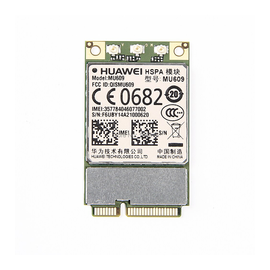
HUAWEI MU609 HSPA LGA Module Hardware Guide Mechanical Specifications 6.6 Label The label is made from deformation-resistant, fade-resistant, and high-temperature-resistant material and is able to endure the high temperature of 260° C. Figure 6-2 MU609 label R=1mm 28mm 1.1*1.1mm 28mm The picture mentioned above is only for reference. -
Page 67: Solder Mask
HUAWEI MU609 HSPA LGA Module Hardware Guide Mechanical Specifications Figure 6-3 MU609 Footprint design (unit: mm) 6.7.3 Solder Mask NSMD is recommended. In addition, the solder mask of the NSMD pad design is larger than the pad so the reliability of the solder joint can be improved. -
Page 68: Assembly Processes
Figure 6-4 Recommended stencil design of LGA module (unit: mm) The stencil design has been qualified for HUAWEI motherboard assembly, customers can adjust the parameters by their motherboard design and process situation to assure LGA soldering quality and no defect. -
Page 69: Reflow Profile
HUAWEI MU609 HSPA LGA Module Hardware Guide Mechanical Specifications 6.8.3 Reflow Profile For the soldering temperature of the LGA module, see the following figure. Figure 6-5 Reflow profile Table 6-2 Reflow parameters Temperature Zone Time Key Parameter Preheat zone 60s–120s Heating rate: 0.5°... -
Page 70: Specification Of Rework
HUAWEI MU609 HSPA LGA Module Hardware Guide Mechanical Specifications 6.9 Specification of Rework 6.9.1 Process of Rework 6.9.2 Preparations of Rework Remove barrier or devices that can’t stand high temperature before rework. If the device to be reworked is beyond the storage period, bake the device according to Table 6-1 . -
Page 71: Welding Area Treatment
HUAWEI MU609 HSPA LGA Module Hardware Guide Mechanical Specifications Figure 6-6 Equipment used for rework 6.9.4 Welding Area Treatment Step 1 Remove the old solder by using a soldering iron and solder braid that can wet the solder. Step 2 Clean the pad and remove the flux residuals. - Page 72 HUAWEI MU609 HSPA LGA Module Hardware Guide Mechanical Specifications Figure 6-7 Temperature graph of rework Huawei Proprietary and Confidential Issue 04 (2016-12-12) Copyright © Huawei Technologies Co., Ltd.
-
Page 73: Certifications
7.1 About This Chapter This chapter gives a general description of certifications of MU609. 7.2 Certifications Table 7-1 shows certifications the MU609 has been implemented. For more demands, please contact us for more details about this information. Table 7-1 Product Certifications... -
Page 74: Safety Information
HUAWEI MU609 HSPA LGA Module Hardware Guide Safety Information Safety Information Read the safety information carefully to ensure the correct and safe use of your wireless device. Applicable safety information must be observed. 8.1 Interference Power off your wireless device if using the device is prohibited. Do not use the wireless device when it causes danger or interference with electric devices. -
Page 75: Traffic Security
HUAWEI MU609 HSPA LGA Module Hardware Guide Safety Information Area indicated with the "Power off bi-direction wireless equipment" sign Area where you are generally suggested to stop the engine of a vehicle 8.4 Traffic Security Observe local laws and regulations while using the wireless device. To prevent accidents, do not use your wireless device while driving. -
Page 76: Laws And Regulations Observance
HUAWEI MU609 HSPA LGA Module Hardware Guide Safety Information 8.10 Laws and Regulations Observance Observe laws and regulations when using your wireless device. Respect the privacy and legal rights of the others. 8.11 Care and Maintenance It is normal that your wireless device gets hot when you use or charge it. Before you clean or maintain the wireless device, stop all applications and power off the wireless device. -
Page 77: Fcc Statement
Warning: Changes or modifications made to this equipment not expressly approved by HUAWEI may void the FCC authorization to operate this equipment. Huawei Proprietary and Confidential Issue 04 (2016-12-12) -
Page 78: Appendix A Circuit Of Typical Interface
HUAWEI MU609 HSPA LGA Module Hardware Guide Appendix A Circuit of Typical Interface Appendix A Circuit of Typical Interface J302 C371 22pF MAIN_ANT C365 22pF SMA6251A1_060_20GHT50GH_50 J303 C372 22pF AUX_ANT C366 22pF J301 These are impedance matching SIM_VCC circuit, the specific capacitance... -
Page 79: Appendix B Acronyms And Abbreviations
HUAWEI MU609 HSPA LGA Module Appendix B Acronyms and Hardware Guide Abbreviations Appendix B Acronyms and Abbreviations Acronym or Abbreviation Expansion 3GPP Third Generation Partnership Project 8PSK 8 Phase Shift Keying Auxiliary Bit Error Rate BLER Block Error Rate BIOS... - Page 80 HUAWEI MU609 HSPA LGA Module Appendix B Acronyms and Hardware Guide Abbreviations Acronym or Abbreviation Expansion Electromagnetic Compatibility Electrostatic Discharge European Union Federal Communications Commission GMSK Gaussian Minimum Shift Keying GPIO General-purpose I/O GPRS General Packet Radio Service Global Positioning System...
- Page 81 HUAWEI MU609 HSPA LGA Module Appendix B Acronyms and Hardware Guide Abbreviations Acronym or Abbreviation Expansion Product IDentity Power Management Unit Radio Frequency Restriction of the Use of Certain Hazardous RoHS Substances Short Message Service Total Isotropic Senstivity Total Radiated Power...