
Related Manuals for Mitsubishi Electric FR-A5NPA


Summary of Contents for Mitsubishi Electric FR-A5NPA
- Page 1 MITSUBISHI ELECTRIC FR-A5NPA Frequency Inverter Instruction Manual Profibus/DP Communication Option Art. no.: 146529 INDUSTRIAL AUTOMATION 01 02 2003 MITSUBISHI ELECTRIC Version B IB(NA)-0600095-B...
- Page 2 Thank you for choosing the Mitsubishi transistorized inverter option unit. This instruction manual gives handling information and precautions for use of this equipment. Incorrect handling might cause an unexpected fault. Before using the equipment, please read this manual carefully to use the equipment to its optimum.
- Page 3 2. Injury Prevention CAUTION • • • • Apply only the voltage specified in the instruction manual to each terminal to prevent burst, damage, etc. • • • • Ensure that the cables are connected to the correct terminals. Otherwise, burst, damage, etc.
-
Page 4: Table Of Contents
CONTENTS 1. PRE-OPERATION INSTRUCTIONS Unpacking and Product Confirmation ..........1 Packing Confirmation................ 1 Structure ................... 2 Inverter Specifications ..............3 Communication Specification ............3 2. INSTALLATION Pre-Installation Instructions .............. 4 Inverter Node Address Setting............4 Installation and Removal Procedure..........5 2.3.1 Profibus Communication Cable .......... - Page 5 5.3.2 Buffer memory map ..............32 5.3.3 Points to note................32 6. BUFFER MEMORY DETAILS FR-A500/F500 Series ..............33 FR-V500 Series ................40 7. PARAMETER DEFINITIONS - A500/F500 SERIES Outline of PNU................47 Profibus PNU .................. 48 7.2.1 Real-time monitor ..............48 7.2.2 Parameter clear ...............
-
Page 6: Pre-Operation Instructions
1. PRE-OPERATION INSTRUCTIONS 1.1 Unpacking and Product Confirmation Take the option unit out of the package, check the unit name, and confirm that the product is as you ordered and intact. Note that the FR-A500/F500 series inverter and FR-V500 series inverter have different functions when the option is fitted. -
Page 7: Structure
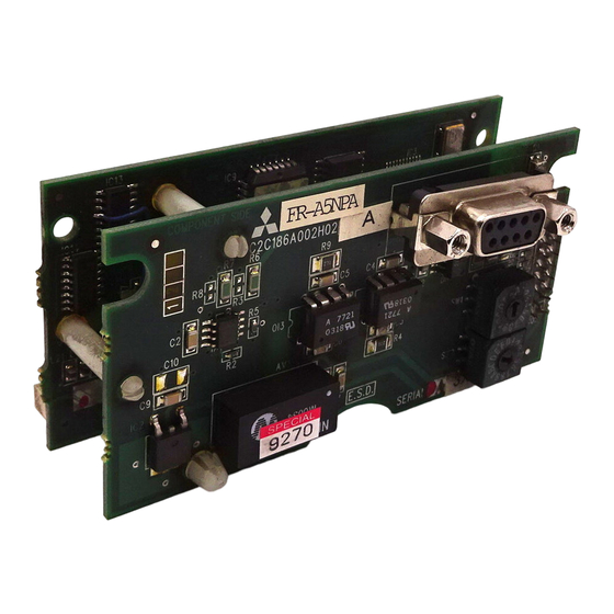
PRE-OPERATION INSTRUCTIONS 1.3 Structure Front view Mounting Mounting FR-A5NPA hole hole Profibus connector (Dsub9 pin connector) Node address switch Operating status Option fixing hole indicator LED Rear view Mounting Mounting hole hole connector Option fixing hole Name Function Used to set the inverter station number between 0... -
Page 8: Inverter Specifications
One inverter occupies one node. occupied For 12Mbps communication Cable (compliant with EEIA-RS-485 standard) When the option unit (FR-A5NPA) is plugged in, the protective structure (JEM1030) is open type (IP00). 1.5 Communication Specification Wiring length 1200m 9600bps, 19.2Kbps, 93.75Kbps maximum Wiring length 600m 187.5Kbps... -
Page 9: Installation
2. INSTALLATION 2.1 Pre-Installation Instructions Make sure that the input power of the inverter is off. CAUTION With input power on, do not install or remove the option unit. Otherwise, the inverter and option unit may be damaged. 2.2 Inverter Node Address Setting Set the node address of the inverter on the Profibus network. -
Page 10: Installation And Removal Procedure
Slot 1 Accessory screw Slot 2 (2 pcs.) Option fixing hook DATA PORT Inverter side connector Slot 3 Option unit (FR-A5NPA) Dsub9 pin Profibus communication male cable connector The slots 1, 2, and 3 are provided with an option fixing hook. - Page 11 Perform wiring after the option unit (FR-A5NPA) was fitted and the inverter front cover was mounted. The option unit (FR-A5NPA) is valid only if it is fitted in slot 3. When two or more communication option units are mounted, "E.OPT" error is displayed.
-
Page 12: Profibus Communication Cable
*1 It may not be necessary depending on the master module used. *2 This signal is used to make the terminating resistor present. (2) Terminating resistor If the nodes at both ends of the network are the FR-A5NPA and inverter, connect a connector with a built-in terminating resistor. R1=390Ω±2% 1/4W 1 2 3 4 5 R2=220Ω±2% 1/4W... -
Page 13: Inverter Setting
3. INVERTER SETTING 3.1 List of Dedicated Communication Parameters When this option unit is mounted, extended functions of the following parameters become available. Perform setting as required. FR-A500/F500 series parameter Minimum Refer Parameter Setting Factory Name Setting Number Range Setting Increments page Operation control... -
Page 14: Operation Mode
INVERTER SETTING 3.2 Operation Mode The inverter mounted with the option unit (FR-A5NPA) has the following operation modes: (1) PU operation [PU] ....Controls the inverter from the keyboard of the operation panel (FR-DU04( )) or parameter unit (FR-PU04(V)) (referred to as the "PU") installed to the inverter. -
Page 15: Operation Mode Switching
INVERTER SETTING 3.2.2 Operation mode switching (1) Operation mode switching conditions Before switching the operation mode, check that: 1) The inverter is at a stop; 2) Both the STF and STR signals are off; and 3) The Pr. 79 "operation mode selection" setting is correct. (For setting, use the inverter's operation panel or optional parameter unit.) Pr. - Page 16 INVERTER SETTING (2) Operation mode switching method Switched Switched via Profibus from PU master module Network External PU operation operation operation (Switching disallowed) Symbol Switching Type Switching Method PU operation Operate the external operation key on the PU. → External operation External operation Operate the PU operation key on the PU.
- Page 17 INVERTER SETTING (3) Link startup mode selection (Pr. 340) The operation mode at power on and at restoration from instantaneous power failure can be selected. To choose the network operation mode, set "1" or "2" in Pr. 340. After the link has started, parameter write is enabled by the Profibus master module.
- Page 18 INVERTER SETTING Pr. 340 Mode at Power On or at Restoration Operation Mode Setting from Instantaneous Power Failure Pr. 79 Inverter operates in the network operation mode. PU or network (Profibus master module need not be used for operation switching) PU operation Inverter operates in the PU operation mode.
- Page 19 INVERTER SETTING REMARKS 1. The Pr. 340 value may be changed from the PU in any operation mode. 2. Computer programming, which has stopped due to an instantaneous power failure or like during network operation, remains stopped even if power is recovered.
-
Page 20: Operation And Speed Command Source
INVERTER SETTING 3.3 Operation and Speed Command Source In the network operation mode, commands from the external terminals and Profibus master module are as listed below. (For Pr. 180 and higher (input terminal function selection), assigned signals differ depending on inverters. For details, refer to the inverter manual.) 3.3.1 FR-A500/F500 series Pr. - Page 21 INVERTER SETTING Pr. 338 "operation control 0: NET 0: NET 1: External 1: External Control command source" location REMARKS Pr. 339 "speed command selection 0: NET 1: External 0: NET 1: External source" Load pattern selection-forward/ reverse rotation boost switching External External (X17) 18 Magnetic flux-V/F switching (X18)
-
Page 22: Fr-V500 Series
INVERTER SETTING 3.3.2 FR-V500 series Pr. 338 "operation control 0: NET 0: NET 1: External 1: External Control command source" location REMARKS Pr. 339 "speed command selection 0: NET 1: External 0: NET 1: External source" Forward rotation command (STF) External External Reverse rotation command (STR) External External... - Page 23 INVERTER SETTING *1 For details of Pr. 180 to Pr. 183, Pr. 187 (input terminal function selection), refer to the inverter manual. *2 When the MRS signal is assigned for both network and external control, the output stop command is as indicated in the following table. Output Stop Command Network External...
-
Page 24: Operation At Communication Error Occurrence
INVERTER SETTING 3.4 Operation at Communication Error Occurrence 3.4.1 Operation selection at communication error occurrence (For the FR-A500/V500 series only) You can select operations at error occurrences by setting Pr. 500 to Pr. 502 under network operation. REMARKS For the FR-A500, Pr. 500 to Pr. 502 are available with an upgraded inverter. Refer to the inverter manual for the availability of the parameters. - Page 25 INVERTER SETTING 2) Pr. 501 "communication error occurrence count display" The cumulative number of communication error occurrences can be indicated. Write 0 to erase this cumulative count. Minimum Setting Parameter Number Setting Range Factory Setting Increments Abnormal Normal Normal Abnormal Count timing depending on communication line status Incremented by 1...
- Page 26 INVERTER SETTING 3) Pr. 502 "communication error-time stop mode selection" You can select the inverter operation if a communication line fault or a fault of the option unit itself occurs. Minimum Setting Parameter Number Setting Range Factory Setting Increments 0, 1, 2 About setting •...
- Page 27 INVERTER SETTING CAUTION 1. A communication line fault [E.OP3 (alarm data: HA3)] is a fault that occurs on the communication line, and a fault of the option unit itself [E. 3 (alarm data: HF3)] is a communication circuit fault in the option. 2.
-
Page 28: Alarm And Measures
(Refer to page 2 for the LED indication line alarm status.) Check the Profibus master module. Check the connection between the inverter and option unit (FR-A5NPA) for poor E. 3 Option alarm contact, etc. and remove the cause of the alarm. -
Page 29: Inverter Reset
INVERTER SETTING 3.4.3 Inverter reset Which resetting method is allowed or not allowed in each operation mode is described below. Operation Mode Resetting Method Network External operation operation operation Inverter reset • Inverter reset can be made Allowed Disallowed Disallowed any time. -
Page 30: Function Overview
4. FUNCTION OVERVIEW 4.1 Function Overview The following table lists the functions that can be controlled from the Profibus master module. Operation Mode Control Item External Network Location operation operation operation Operation command/Output Disallowed Disallowed Allowed frequency setting Monitor Allowed Allowed Allowed Disallowed... -
Page 31: Input From Master Module To Inverter
*2 Signals can be assigned using input terminal function selection (Pr. 400 to Pr. 402). Refer to page 8. (when the FR-A5NPA is connected) (2) Set frequency/set speed Write a setting change from the master module to the inverter. (Refer to pages 38, 45.) -
Page 32: Output From Inverter To Master Module
FUNCTION OVERVIEW 4.1.2 Output from inverter to master module (1) Monitor function You can monitor the following items from the master module. 1) Running frequency :0.01Hz increments (FR-A500/F500 series) (Refer to page 38.) Running speed : 1r/min increments (FR-V500 series) (Refer to page 45.) 2) Alarm definition : Refer to page 51 for the FR-A500/F500 series and page 61 for the FR-V500 series. -
Page 33: Profibus Profiles
5.1 Profibus Device Data MEAU0865A. GSD is a GSD file designed to recognize the features and functions of the Profibus DP devices of the FR-A5NPA. You can obtain it from us. Please contact your sales representative. When editing this file, use a text editor. - Page 34 Profibus PROFILES Parameter Value Description*1 Longest time 150 bit times MaxTsdr_1.5M at 1.5MKbps communication speed Longest time 250 bit times MaxTsdr_3.0M at 3.0Mbps communication speed Longest time 450 bit times MaxTsdr_6.0M at 6.0Mbps communication speed Longest time 800 bit times MaxTsdr_12.0M at 12.0Mbps communication speed Redundancy...
-
Page 35: Slave User Parameter
Profibus PROFILES Parameter Value Description*1 Ext_User_Prm_Data_ Initial value of user parameter's second Const(1) byte Ext_User_Prm_Data_ Byte swapping selection 1 is used on text Ref(1) base in user parameter's second byte. " " PPO type 1 Module PPO type 1 selection , F1 EndModule "... -
Page 36: Profibus Profiles
Profibus PROFILES 5.3 Profibus Profiles The option unit operates as a "slave of the Profibus DP master" or a "controller equivalent to Profibus DP master class 1 on an RS-485 network". The Profibus profile (data buffer) can be selected from among five different types, "PPO type 1"... -
Page 37: Buffer Memory Map
Profibus PROFILES 5.3.2 Buffer memory map The following shows the buffer memory map of the PPO type 1 to PPO type 5 Profibus profiles. 2Word 3Word 4Word 5Word 6Word 7Word 8Word 9Word 10Word11Word 12Word13Word14Word 1Word HSW/ STW/ type 1 Reser- STW/ HSW/ ECW/... -
Page 38: Buffer Memory Details
6. BUFFER MEMORY DETAILS 6.1 FR-A500/F500 Series The following indicates the buffer memory details of the FR-A500/F500 series Profibus profiles. Master→ → → → Slave (command request) 15 141312 1110 9 8 7 6 5 4 3 2 1 0 PNU (parameter number) Task SPM Not support... - Page 39 BUFFER MEMORY DETAILS → → → → Master (command response) Slave 1514 13121110 9 8 7 6 5 4 3 2 1 0 PNU (parameter number) Response SPM Not support 1514 13121110 9 8 7 6 5 4 3 2 1 0 Sub-Index reserved 31 30 29 28 27 26 25 24 23 22 21 20 19 18 17 16...
- Page 40 BUFFER MEMORY DETAILS FR-A500/F500 series Name Description 0 to 10 PNU number Not used (0 is set) [Command request] 0:No task 1:Parameter value is requested (read request) 2:Parameter value (word) is changed (write request 3 to 5:Not supported 6:Parameter value (array) is requested (read request) 7:Parameter value (array word) is changed (write 12 to...
- Page 41 BUFFER MEMORY DETAILS FR-A500/F500 series Name Description PNU read value/write value When command response AK = 7 (command execution error), PWE definition is as follows. Error Definition 0 Invalid PNU Parameter value unchangeable (This error also occurs when Pr. 77 = 1) 2 Outside setting range 3 Invalid Sub-Index number 4 No array...
- Page 42 BUFFER MEMORY DETAILS FR-A500/F500 series Name Description 0 to 2 Not used (1 is set) Control 0:Inverter output shutoff enable 1:Inverter output shutoff is cancelled 4 to 6 Not used (1 is set) [At inverter error] 0:No action Fault 1:Inverter reset reset [When inverter is normal] No action...
- Page 43 BUFFER MEMORY DETAILS FR-A500/F500 series Name Description 0 to 2 Not used (1 is returned) Fault 0:Inverter normal (Alarm 1:Inverter alarm occurrence signal) 4 to 5 Not used (1 is returned) Power- 0 is returned on inhibit 0:Command execution normal Alarm 1:Command execution error Not used (0 is returned)
- Page 44 BUFFER MEMORY DETAILS FR-A500/F500 series Name Description 0:RH-OFF 1:RH-ON terminal Factory-set to high-speed operation command Pr. 182 can be used to change the signal. (*1) 0:RM-OFF 1:RM-ON terminal Factory-set to middle-speed operation command Pr. 181 can be used to change the signal. (*1) 0:RL-OFF 1:RL-ON terminal...
-
Page 45: Fr-V500 Series
BUFFER MEMORY DETAILS 6.2 FR-V500 Series The following indicates the buffer memory details of the FR-V500 series Profibus profiles. Master → → → → Slave (command request) 151413121110 9 8 7 6 5 4 3 2 1 0 PNU (parameter number) Task SPM Not support 151413121110 9 8 7 6 5 4 3 2 1 0... - Page 46 BUFFER MEMORY DETAILS → → → → Master (command response) Slave 15 141312 1110 9 8 7 6 5 4 3 2 1 0 PNU (parameter number) Response SPM Not support 15 141312 1110 9 8 7 6 5 4 3 2 1 0 Sub-Index reserved 31 30 29 28 27 26 25 24 23 22 21 20 19 18 17 16...
- Page 47 BUFFER MEMORY DETAILS FR-V500 series Name Description 0 to 10 PNU number Not used (0 is set) [Command request] 0:No task 1:Parameter value is requested (read request) 2:Parameter value (word) is changed (write request) 3 to 5:Not supported 6:Parameter value (array) is requested (read request) 7:Parameter value (array word) is changed (write 12 to...
- Page 48 BUFFER MEMORY DETAILS FR-V500 series Name Description PNU read value/write value When command response AK = 7 (command execution error), PWE definition is as follows. Error Definition 0 Invalid PNU Parameter value unchangeable (This error also occurs when Pr. 77 = 1) 2 Outside setting range 3 Invalid Sub-Index number 4 No array...
- Page 49 BUFFER MEMORY DETAILS FR-V500 series Name Description 0 to 2 Not used (1 is set) Control 0:Inverter output shutoff enable 1:Inverter output shutoff is cancelled 4 to 6 Not used (1 is set) [At inverter error] 0:No action Fault 1:Inverter reset reset [When inverter is normal] No action...
- Page 50 BUFFER MEMORY DETAILS FR-V500 series Name Description 0 to 2 Not used (1 is returned) Fault 0:Inverter normal (Alarm 1:Inverter alarm occurrence signal) 4 to 5 Not used (1 is returned) Power- 0 is returned on inhibit 0:Command execution normal Alarm 1:Command execution error Not used (0 is returned)
- Page 51 BUFFER MEMORY DETAILS FR-V500 series Name Description 0:RL-OFF 1:RL-ON terminal Factory-set to low-speed operation command Pr. 180 can be used to change the signal. (*1) 0:RM-OFF 1:RM-ON terminal Factory-set to middle-speed operation command Pr. 181 can be used to change the signal. (*1) 0:RH-OFF 1:RH-ON terminal...
-
Page 52: Parameter Definitions - A500/F500 Series
7. PARAMETER DEFINITIONS - A500/F500 SERIES 7.1 Outline of PNU You can use the PNU to make inverter settings from the network. The data used with the network is denoted P for PNU to differentiate it from Pr. for parameter. CAUTION The parameter definitions differ between the FR-A500/F500 and FR- V500 series. -
Page 53: Profibus Pnu
PARAMETER DEFINITIONS - A500/F500 SERIES 7.2 Profibus PNU 7.2.1 Real-time monitor The following items can be monitored from the master. Data Item Unit Type P1.1 Output frequency 0.01Hz AUs16 P1.2 Output current 0.01A AUs16 P1.3 Output voltage 0.1V AUs16 P1.5 Frequency setting 0.01Hz AUs16... - Page 54 PARAMETER DEFINITIONS - A500/F500 SERIES (1) External input terminal status PWE bitmap Terminal STOP JOG* name Not used (system reserved) * Pr. 180 to 186 can be used to assign the terminal functions. Refer to the inverter manual for details of the terminal functions. (2) External output terminal status PWE bitmap Terminal ABC*...
-
Page 55: Parameter Clear
PARAMETER DEFINITIONS - A500/F500 SERIES 7.2.2 Parameter clear Parameter clear can be performed from the master. Item Data Definition Data Type P2.1 User clear value setting Set parameter number AUs16 P2.2 Parameter clear 965AH AUs16 P2.3 Parameter all clear 99AAH AUs16 P2.4 Parameter user clear 5A55H... -
Page 56: Node Address Read
PARAMETER DEFINITIONS - A500/F500 SERIES 7.2.7 Node address read The node address of the inverter can be read. Item Data Definition Data Type P918 Node address read Set node address is read. Us16 7.2.8 Alarm history The eight past error definitions of the inverter can be read. Item Data Definition Data Type... -
Page 57: Pnu List Read
PARAMETER DEFINITIONS - A500/F500 SERIES 7.2.9 PNU list read The usable PNU numbers can be read. Item Data Definition Data Type P980.1 to 116 P981.1 to 116 P982.1 to 116 P983.1 to 116 P984.1 to 116 Usable PNU numbers are read in PNU list read AUs16 P985.1 to 116... -
Page 58: Standard Parameters
0 to 400 0 to 9C40 P1006 setting 0.01Hz Us16 (F500) (F500) (Low 0 to 120 0 to 2EE0 speed) CAUTION Write to Pr. 77 and Pr. 79 is not allowed from the network with the FR-A5NPA. (Read is allowed.) - Page 59 PARAMETER DEFINITIONS - A500/F500 SERIES The following parameters require the Sub-Index number for the PNU. Minimum Setting Range Data Name Setting Type Remarks Number Decimal Hexadecimal Increments P1201.1 Program setting 1 0.01 0 to 99.59 0 to 26E7 AUs16 P1210.1 (Time) Program P1201.2...
- Page 60 PARAMETER DEFINITIONS - A500/F500 SERIES Minimum Setting Range Data Name Setting Remarks Number Type Decimal Hexadecimal Increments Frequency (A500) (A500) setting 1 to 400 64 to 9C40 P1903.1 0.01Hz AUs16 voltage gain (F500) (F500) (frequency) 1 to 120 64 to 2EE0 Frequency setting P1903.2...
-
Page 61: Parameter Definitions - V500 Series
8. PARAMETER DEFINITIONS - V500 SERIES 8.1 Outline of PNU You can use the PNU to make inverter settings from the network. The data used with the network is denoted PNU(P) to differentiate it from the parameter (Pr.). CAUTION The parameter definitions differ between the FR-V500 and A500/ F500 series. -
Page 62: Profibus Pnu
PARAMETER DEFINITIONS - V500 SERIES 8.2 Profibus PNU 8.2.1 Real-time monitor The following items can be monitored from the master. Data Item Unit Type P1.1 Output frequency 0.01Hz AUs16 P1.2 Output current 0.01A AUs16 P1.3 Output voltage 0.1V AUs16 P1.5 Speed setting 1r/min AUs16... - Page 63 PARAMETER DEFINITIONS - V500 SERIES (1) External input terminal status PWE bitmap Terminal RES* DI4* DI3* DI2* DI1* STR* name Not used (system reserved) * Pr. 180 to Pr. 183 and Pr. 187 can be used to assign the terminal functions.
-
Page 64: Parameter Clear
PARAMETER DEFINITIONS - V500 SERIES 8.2.2 Parameter clear Parameter clear can be performed from the master. Item Data Definition Data Type P2.2 Parameter clear 965AH AUs16 P2.3 Parameter all clear 99AAH AUs16 P2.5 Parameter clear (*1) 5A96H AUs16 P2.6 Parameter all clear (*1) AA99H AUs16 P2.8 Error history clear... -
Page 65: Terminal Input Read
PARAMETER DEFINITIONS - V500 SERIES 8.2.5 Terminal input read The setting of the No. 2 terminal can be read. Item Data Definition Data Type No. 2 terminal input No. 2 terminal input value read Us16 value (%) is read. 8.2.6 Inverter reset The inverter can be reset from the master. -
Page 66: Alarm History
PARAMETER DEFINITIONS - V500 SERIES 8.2.8 Alarm history The eight past error definitions of the inverter can be read. Item Data Definition Data Type P947.1 to Error history No. 1 P947.1 :Error number AUs16 P947.8 read P947.2 to P947.8 :All 0 P947.9 to Error history No. -
Page 67: Pnu List Read
PARAMETER DEFINITIONS - V500 SERIES 8.2.9 PNU list read The usable PNU numbers can be read. Item Data Definition Data Type P980.1 to 116 P981.1 to 116 P982.1 to 116 P983.1 to 116 P984.1 to 116 Usable PNU numbers are read in PNU list read AUs16 P985.1 to 116... -
Page 68: Standard Parameters
0 to E10 Us16 (Middle speed) Multi- speed P1006 setting 1r/min 0 to 3600 0 to E10 Us16 (Low speed) CAUTION Write to Pr. 77 and Pr. 79 is not allowed from the network with the FR-A5NPA. (Read is allowed.) - Page 69 PARAMETER DEFINITIONS - V500 SERIES The following parameters require the Sub-Index number for the PNU. Minimum Setting Range Data Name Setting Type Remarks Number Decimal Hexadecimal Increments P1900.1 terminal AUs16 calibration P1901.1 terminal AUs16 calibration Speed P1902.1 setting No. 2 0.1r/min 0 to 3600 0 to 8CA0...
- Page 70 PARAMETER DEFINITIONS - V500 SERIES Minimum Setting Range Data Name Setting Remarks Number Type Decimal Hexadecimal Increments No. 1 P1918.1 terminal 1r/min 0 to 3600 0 to E10 AUs16 Speed gain (speed) No. 1 P1918.2 terminal 0.1% AUs16 Speed gain (%) No.
-
Page 71: Troubleshooting
9. TROUBLESHOOTING If an alarm occurred in the inverter and the inverter and option unit do not function, refer to the following check points, find the cause from the operation panel indication of the inverter and the LED status of the option unit, and take an appropriate action. - Page 72 REVISIONS *The manual number is given on the bottom left of the back cover. Print Date *Manual Number Revision May, 2002 IB(NA)-0600095-A First edition Feb., 2003 IB(NA)-0600095-B Additions • Command count • Inverter reset command...
- Page 73 MITSUBISHI ELECTRIC HEADQUARTERS EUROPEAN REPRESENTATIVES EUROPEAN REPRESENTATIVES EUROPEAN REPRESENTATIVES MITSUBISHI ELECTRIC EUROPE GEVA AUSTRIA SIA POWEL LATVIA TURKEY EUROPE B.V. Wiener Straße 89 Lienes iela 28 Darülaceze Cad. No. 43A KAT: 2 German Branch A-2500 Baden LV-1009 Riga TR-80270 Okmeydani-Istanbul Gothaer Straße 8...