Table of Contents
Quick Links
Installation & Maintenance
Instructions MM-601(C)
Series FS4-3
General Purpose
Liquid Flow Switch
(specified models only)
OPERATION
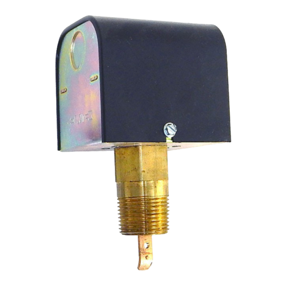
This control is an independently mounted water flow
sensing device that makes or breaks an electrical
circuit when flow stops or starts.
• Before using product, read and understand instructions.
• Save these instructions for future reference.
• All work must be performed by qualified personnel trained in the proper application,
installation, and maintenance of plumbing, steam and electrical equipment and/or systems in
accordance with all applicable codes and ordinances.
• To prevent electrical shock, turn off the electrical power before making electrical
connections.
• To prevent an electrical fire or equipment damage, electrical wiring insulation must have a
rating of 167˚F (75˚C) if the liquid's temperature exceeds 180˚F (82˚C).
• To prevent electrocution, when the electrical power is connected to the flow switch, do not
touch the terminals.
• Make sure flow switch electrical cover is secured before turning on electric power.
Failure to follow this warning could cause property damage, personal injury or death.
®
Now
with
Stainless Steel
Paddles
!
WARNING
F L O
W
Series FS4-3
Table of Contents

Summary of Contents for McDonnell & Miller FS4-3 Series
- Page 1 Installation & Maintenance Instructions MM-601(C) Series FS4-3 ® General Purpose Liquid Flow Switch F L O (specified models only) with Stainless Steel Paddles Series FS4-3 OPERATION This control is an independently mounted water flow sensing device that makes or breaks an electrical circuit when flow stops or starts.
-
Page 2: Specifications
SPECIFICATIONS Maximum Liquid Pressure: 160 psi (11.3 kg/cm Liquid Temperature Range (T ): 32 - 300˚F (0 - 149˚C) Ambient Temperature Range (T ): 32 - 120˚F (0 - 49˚C) Electrical Enclosure Rating: Nema Type 1 (IP 21) Maximum Velocity: 10ft/sec (3M/sec) Pipe Connection Thread Size: - 1”... -
Page 3: Flow Rates
FLOW RATES Flow rates required to activate flow switch are shown Settings will vary when used to sense flow of other in chart below. The values are calculated for sensing fluids or if located in a vertical pipe. water (potable, non-polluted) in a horizontal pipe. NOTE: DO NOT USE LIQUID FLOW SWITCHES Max. -
Page 4: Installation
INSTALLATION – STEP 1 - Paddle Sizing Determine the correct paddle length for your installation from the chart below. Pipe Size Paddle Trim to Length (Standard Length) (mm) (mm) (mm) 1" (25mm) (25) (25) 2" (51mm) (32) (51) (32) (40) (51) (38) 3"... - Page 5 STEP 2 - Determine the Location of the Flow Switch • The flow switch should be located in a horizontal section of pipe where there is a straight horizontal run of at least 5 pipe diameters on each side of the flow switch.
-
Page 6: Step 4 - Electrical Installation
b. Apply pipe sealing compound or Teflon tape to the flow switch pipe threads. ® Teflon NOTE: Do not apply sealant to first threads as this F L O switch is grounded (earthed) via the pipe mounting. c. Insert the flow switch into the pipe tee. Turn the flow switch two (2) or three (3) revolutions FLOW clockwise until tight. - Page 7 b. Electrical Conduit Connection • Connect electric conduit to flow switch electrical enclosure. • Follow accepted electrical practices when installing fittings and making connections. • Refer to and follow local codes and standards when selecting the types of electrical fittings and conduit to connect to flow switch.
-
Page 8: Maintenance
STEP 6 - Adjustment Adjustment is necessary only if required flow/no- Single Switch Models Double Switch Models flow setpoints are above factory set minimum. a. Turn off power. Remove switch cover. b. Turn the adjusting screw clockwise to increase setpoint. IMPORTANT: Do not attempt to lower flow switch setpoint from original factory minimum setting.