Siemens SIMATIC S7-1500 Manual
Hide thumbs
Also See for SIMATIC S7-1500:
- Function manual (402 pages) ,
- System manual (393 pages) ,
- Manual (188 pages)
Table of Contents
Table of Contents

Related Manuals for Siemens SIMATIC S7-1500


Summary of Contents for Siemens SIMATIC S7-1500
- Page 2 ___________________ Preface ___________________ Documentation guide ___________________ SIMATIC Product overview ___________________ Connecting up S7-1500 CPU 1511-1 PN Interrupts, error messages, ___________ diagnostics and system (6ES7511-1AK02-0AB0) alarms ___________________ Manual Technical specifications ___________________ Dimensional drawing 12/2017 A5E40869673-AA...
- Page 3 Note the following: WARNING Siemens products may only be used for the applications described in the catalog and in the relevant technical documentation. If products and components from other manufacturers are used, these must be recommended or approved by Siemens. Proper transport, storage, installation, assembly, commissioning, operation and maintenance are required to ensure that the products operate safely and without any problems.
-
Page 4: Preface
Siemens' products and solutions undergo continuous development to make them more secure. Siemens strongly recommends that product updates are applied as soon as they are available and that the latest product versions are used. Use of product versions that are no longer supported, and failure to apply the latest updates may increase customers' exposure to cyber threats. - Page 5 This information is provided by the Siemens Industry Online Support in the Internet (https://support.industry.siemens.com). Industry Mall The Industry Mall is the catalog and order system of Siemens AG for automation and drive solutions on the basis of Totally Integrated Automation (TIA) and Totally Integrated Power (TIP).
-
Page 6: Table Of Contents
Table of contents Preface ..............................4 Documentation guide ..........................7 Product overview ..........................11 Applications of the S7-1500 CPU ..................11 Hardware properties ......................18 Firmware functions ......................... 20 Operating and display elements .................... 24 2.4.1 Front view of the CPU with closed front panel ............... 24 2.4.2 Front view of the CPU without front panel and view from below ........... -
Page 7: Documentation Guide
This arrangement enables you to access the specific content you require. Basic information The System Manual and Getting Started describe in detail the configuration, installation, wiring and commissioning of the SIMATIC S7-1500 and ET 200MP systems. The STEP 7 online help supports you in the configuration and programming. Device information Product manuals contain a compact description of the module-specific information, such as properties, wiring diagrams, characteristics and technical specifications. - Page 8 You can download the product information free of charge from the Internet (https://support.industry.siemens.com/cs/us/en/view/68052815). Manual Collection S7-1500/ET 200MP The Manual Collection contains the complete documentation on the SIMATIC S7-1500 automation system and the ET 200MP distributed I/O system gathered together in one file. You can find the Manual Collection on the Internet (https://support.industry.siemens.com/cs/ww/en/view/86140384).
- Page 9 ● Manuals, characteristics, operating manuals, certificates ● Product master data You can find "mySupport" - CAx data on the Internet (http://support.industry.siemens.com/my/ww/en/CAxOnline). Application examples The application examples support you with various tools and examples for solving your automation tasks. Solutions are shown in interplay with multiple components in the system - separated from the focus on individual products.
- Page 10 You can find the SIMATIC Automation Tool on the Internet (https://support.industry.siemens.com/cs/ww/en/view/98161300). PRONETA With SIEMENS PRONETA (PROFINET network analysis), you analyze the PROFINET network during commissioning. PRONETA features two core functions: ● The topology overview independently scans PROFINET network and all connected components.
-
Page 11: Product Overview
Product overview Applications of the S7-1500 CPU Area of application SIMATIC S7-1500 is the modular control system for a wide variety of automation applications in discrete automation. The modular and fanless design, simple implementation of distributed structures, and user- friendly operation make SIMATIC S7-1500 the economic and convenient solution for a variety of tasks. - Page 12 Product overview 2.1 Applications of the S7-1500 CPU Performance segments of the standard, compact, fail-safe and technology CPUs The CPUs can be used for smaller and mid-range applications, as well as for the high-end range of machine and plant automation. Table 2- 1 Standard CPUs Performance segment...
- Page 13 Product overview 2.1 Applications of the S7-1500 CPU Table 2- 3 Fail-safe CPUs Performance segment PROFIBUS PROFINET PROFINET PROFINET Work memory Pro- interfaces IO RT/IRT IO RT basic func- cessing interfaces interface tionality time for bit operations CPU 1511F-1 PN Fail-safe CPU for small to 1.225 MB 60 ns...
- Page 14 Product overview 2.1 Applications of the S7-1500 CPU Table 2- 4 Technology CPUs Performance segment PROFIBUS PROFINET PROFINET PROFINET Work memory Pro- interfaces IO RT/IRT IO RT basic func- cessing interfaces interface tionality time for bit operations CPU 1511T-1 PN Technology CPU for small 1.225 MB 60 ns...
- Page 15 2.1 Applications of the S7-1500 CPU Integrated Motion Control technology functions All CPUs of SIMATIC S7-1500 support Motion Control technology functions. STEP 7 offers Motion Control instructions standardized according to PLCopen for configuring and connecting a drive to the CPU.
- Page 16 Product overview 2.1 Applications of the S7-1500 CPU Other technology functions Technology modules also implement functions such as high-speed counting, position detection, measuring functions and pulse generators (PTO, PWM and frequency output). For compact CPU 1511C-1 PN and CPU 1512C-1 PN CPUs, these functions are already integrated and can be implemented without additional technology modules.
- Page 17 DIN rail is implemented in the rail of the S7-1500. The CPUs of the SIMATIC S7-1500 product series can be expanded centrally and in a modular fashion with signal modules. Space-saving expansion enables flexible adaptation to each application.
-
Page 18: Hardware Properties
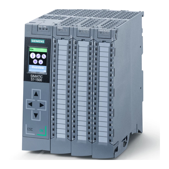
Product overview 2.2 Hardware properties Hardware properties Article number 6ES7511-1AK02-0AB0 View of the module The following figure shows a CPU 1511-1 PN. Figure 2-1 CPU 1511-1 PN Note Protective film Note that a protective film is attached to the display of the CPU when shipped from the factory. - Page 19 CPU 1511-1 PN has the following technical properties: Property Description Additional information CPU display All CPUs of the SIMATIC S7-1500 product series fea- S7-1500, ET 200MP system • ture a display with plain text information. The display manual provides information on order numbers, firmware ver- (http://support.automation.sieme...
-
Page 20: Firmware Functions
The system automatically generates the messages for Diagnostics function manual nostics the system diagnostics and outputs these messages (https://support.industry.siemens.co via a programming device/PC, HMI device, the Web m/cs/ww/en/view/59193560) server or the integrated display. System diagnostics information is also available when the CPU is in STOP mode. - Page 21 PROFINET IO RT (real time) RT prioritizes PROFINET IO telegrams over standard PROFINET function manual telegrams. This ensures the required determinism in (https://support.industry.siemens.co the automation technology. In this process the data is m/cs/ww/en/view/49948856) transferred via prioritized Ethernet telegrams. IRT (isochronous real...
- Page 22 S7-1500 CPUs support the controlled positioning and S7-1500 Motion Control function traveling of axes via S7-1500 Motion Control functions manual by means of the following technology objects: (https://support.industry.siemens.co m/cs/ww/en/view/109749262) Speed-controlled axes, positioning axes, synchronized axes, external encoders, cams, cam tracks and meas- uring inputs.
- Page 23 Know-how protection The know-how protection protects user blocks against S7-1500, ET 200MP system manual unauthorized access and modifications. (https://support.industry.siemens.co m/cs/ww/en/view/59191792) Copy protection Copy protection links user blocks to the serial number of the SIMATIC memory card or to the serial number of the CPU.
-
Page 24: Operating And Display Elements
Product overview 2.4 Operating and display elements Operating and display elements 2.4.1 Front view of the CPU with closed front panel The following figure shows the front view of the CPU 1511-1 PN. ① LEDs for the current operating mode and diagnostics status of the CPU ②... - Page 25 S7-1500, ET 200MP (http://support.automation.siemens.com/WW/view/en/59191792) system manual. Reference You will find detailed information on the individual display options, a training course and a simulation of the available menu commands in the SIMATIC S7-1500 Display Simulator (http://www.automation.siemens.com/salesmaterial-as/interactive-manuals/getting- started_simatic-s7-1500/disp_tool/start_en.html). CPU 1511-1 PN (6ES7511-1AK02-0AB0)
-
Page 26: Front View Of The Cpu Without Front Panel And View From Below
Product overview 2.4 Operating and display elements 2.4.2 Front view of the CPU without front panel and view from below The following figure shows the operator controls and connection elements of the CPU 1511- 1 PN. ① LEDs for the current operating mode and diagnostic status of the CPU ②... -
Page 27: Rear View Of The Cpu
Product overview 2.4 Operating and display elements 2.4.3 Rear view of the CPU The following figure shows the connection elements on the back of the CPU 1511-1 PN. ① Shield contact surface ② Plug-in connection for power supply ③ Plug-in connection for backplane bus ④... -
Page 28: Operating Mode Buttons
You can find additional information in the S7- up yellow. memory card): 1500/ET 200MP system manual 2. Press the operating mode button (https://support.industry.siemens.com/cs/ww/den/ STOP until the RUN/STOP LED view/59191792). lights up for the 2nd time and re- mains continuously lit (this takes three seconds). -
Page 29: Connecting Up
Connecting up This section provides information on the terminal assignment of the individual interfaces and the block diagram of the CPU 1511-1 PN. 24 V DC supply voltage (X80) The connector for the power supply is plugged in when the CPU ships from the factory. The following table shows the pin assignment for a 24 V DC power supply. - Page 30 You need a screwdriver (max. blade width 2.5 mm) to remove the PROFINET plug. Reference You can find additional information on the topics of "Connecting the CPU" and "Accessories/spare parts" in the S7-1500, ET 200MP (http://support.automation.siemens.com/WW/view/en/59191792) system manual. CPU 1511-1 PN (6ES7511-1AK02-0AB0) Manual, 12/2017, A5E40869673-AA...
- Page 31 Connecting up Assignment of the MAC addresses The CPU 1511-1 PN has a PROFINET interface with two ports. The PROFINET interface itself has a MAC address, and each of the two PROFINET ports has its own MAC address. The CPU 1511-1 PN therefore has three MAC addresses in total. The MAC addresses of the PROFINET ports are needed for the LLDP protocol, for example for the neighborhood discovery function.
- Page 32 Connecting up Block diagram The following figure shows the block diagram of the CPU 1511-1 PN. ① CPU with control and operating mode X80 24 V DC Infeed of supply voltage buttons ② Display 24 V DC supply voltage ③ Electronics Ground ④...
-
Page 33: Interrupts, Error Messages, Diagnostics And System Alarms
The status and error displays of the CPU 1511-1 PN are described below. You will find additional information on "Interrupts" in the STEP 7 online help. You can find additional information on the topics of "Diagnostics" and "System alarms" in the Diagnostics (http://support.automation.siemens.com/WW/view/en/59192926) function manual. Status and error display of the CPU LED display The figure below shows the CPU 1511-1 PN LEDs. - Page 34 Interrupts, error messages, diagnostics and system alarms 4.1 Status and error display of the CPU Meaning of the RUN/STOP, ERROR and MAINT LEDs The CPU 1511-1 PN has three LEDs to signal the current operating status and diagnostics status. The following table shows the meaning of the various combinations of colors for the RUN/STOP, ERROR and MAINT LEDs.
- Page 35 Interrupts, error messages, diagnostics and system alarms 4.1 Status and error display of the CPU RUN/STOP LED ERROR LED MAINT LED Meaning Startup (CPU booting) Test of LEDs during startup, inserting a module. LED flashes red LED flashes yellow LED flashes yellow/green LED flashing test Meaning of LINK RX/TX LED...
-
Page 36: Technical Specifications
Technical specifications Article number 6ES7511-1AK02-0AB0 General information Product type designation CPU 1511-1 PN HW functional status FS01 Firmware version V2.5 Engineering with STEP 7 TIA Portal configurable/integrated • as of version Configuration control via dataset Display Screen diagonal [cm] 3.45 cm Control elements Number of keys Mode buttons... - Page 37 Technical specifications Article number 6ES7511-1AK02-0AB0 Work memory 150 kbyte integrated (for program) • 1 Mbyte integrated (for data) • Load memory 32 Gbyte Plug-in (SIMATIC Memory Card), max. • Backup maintenance-free • CPU processing times for bit operations, typ. 60 ns for word operations, typ.
- Page 38 Technical specifications Article number 6ES7511-1AK02-0AB0 Number of asynchronous error OBs • Number of synchronous error OBs • Number of diagnostic alarm OBs • Nesting depth per priority class • Counters, timers and their retentivity S7 counter 2 048 Number • Retentivity –...
- Page 39 Technical specifications Article number 6ES7511-1AK02-0AB0 Address area Number of IO modules 1 024; max. number of modules / submodules I/O address area 32 kbyte; All inputs are in the process image Inputs • 32 kbyte; All outputs are in the process image Outputs •...
- Page 40 Technical specifications Article number 6ES7511-1AK02-0AB0 Clock synchronization supported • in AS, master • in AS, slave • on Ethernet via NTP • Interfaces Number of PROFINET interfaces 1. Interface Interface types Number of ports • integrated switch • Yes; X1 RJ 45 (Ethernet) •...
- Page 41 Technical specifications Article number 6ES7511-1AK02-0AB0 – of which in line, max. 8; in total across all interfaces – Number of IO Devices that can be sim- ultaneously activated/deactivated, max. – Number of IO Devices per tool, max. The minimum value of the update time also de- –...
- Page 42 Technical specifications Article number 6ES7511-1AK02-0AB0 Interface types RJ 45 (Ethernet) 100 Mbps • Autonegotiation • Autocrossing • Industrial Ethernet status LED • Protocols Number of connections 96; via integrated interfaces of the CPU and con- Number of connections, max. • nected CPs / CMs Number of connections reserved for •...
- Page 43 Technical specifications Article number 6ES7511-1AK02-0AB0 SIMATIC communication S7 communication, as server • S7 communication, as client • See online help (S7 communication, user data User data per job, max. • size) Open IE communication TCP/IP • 64 kbyte – Data length, max. –...
- Page 44 Technical specifications Article number 6ES7511-1AK02-0AB0 Isochronous mode Isochronous operation (application synchro- Yes; With minimum OB 6x cycle of 625 µs nized up to terminal) Equidistance S7 message functions Number of login stations for message func- tions, max. Program alarms Number of configurable program alarms 5 000 Number of simultaneously active program alarms...
- Page 45 Technical specifications Article number 6ES7511-1AK02-0AB0 Interrupts/diagnostics/status information Diagnostics indication LED RUN/STOP LED • ERROR LED • MAINT LED • STOP ACTIVE LED • Connection display LINK TX/RX • Supported technology objects Motion Control Yes; Note: The number of axes affects the cycle time of the PLC program;...
- Page 46 Technical specifications Article number 6ES7511-1AK02-0AB0 Ambient conditions Ambient temperature during operation 0 °C horizontal installation, min. • 60 °C; Display: 50 °C, at an operating tempera- horizontal installation, max. • ture of typically 50 °C, the display is switched off 0 °C vertical installation, min.
- Page 47 Technical specifications General technical specifications You can find information on the general technical specifications, such as standards and approvals, electromagnetic compatibility, protection class, etc., in the S7-1500, ET 200MP (http://support.automation.siemens.com/WW/view/en/59191792) system manual. CPU 1511-1 PN (6ES7511-1AK02-0AB0) Manual, 12/2017, A5E40869673-AA...
-
Page 48: A Dimensional Drawing
Dimensional drawing This section includes a dimensional drawing of the module on a mounting rail and a dimensional drawing with the front panel open. Always observe the specified dimensions for installation in cabinets, control rooms, etc. Dimensional drawings for CPU 1511-1 PN Figure A-1 Dimensional drawing of CPU 1511-1 PN, front and side views CPU 1511-1 PN (6ES7511-1AK02-0AB0) - Page 49 Dimensional drawing Figure A-2 Dimensional drawing of CPU 1511-1 PN, side view with front panel open CPU 1511-1 PN (6ES7511-1AK02-0AB0) Manual, 12/2017, A5E40869673-AA...