
Related Manuals for Motorola MINITOR VI


Summary of Contents for Motorola MINITOR VI
- Page 1 MINITOR VI SELECTIVE CALL ALERT MONITOR RECEIVER BASIC SERVICE MANUAL...
-
Page 2: Foreword
No duplication or distribution of this document or any portion thereof shall take place without the express written permission of Motorola. No part of this manual may be reproduced, distributed, or transmitted in any form or by any means, electronic or mechanical, for any purpose without the express written permission of Motorola. -
Page 3: Document History
Document History The following major changes have been implemented in this manual since the previous edition: Edition Description Date 68009688001-A Initial Release Oct 2014... -
Page 4: Table Of Contents
Capacity Warranty .............................xii Chapter 1 Introduction ................. 1-1 Notations Used in This Manual ....................1-1 Pager Description ........................1-1 1.2.1 MINITOR VI ........................1-2 Summary of Bands Available ....................... 1-3 Model Charts..........................1-3 1.4.1 VHF Tanapa Chart......................1-3 1.4.2 UHF Tanapa Chart ......................1-4 Specifications.......................... - Page 5 Back Housing Reasassembly ................. 4-11 4.4.2.2 Front Housing and Back Housing Reasassembly .......... 4-11 Pager Exploded Mechanical View and Parts Lists ..............4-14 4.5.1 MINITOR VI Exploded View and Parts List ..............4-14 Chapter 5 Accessories ................. 5-1 Introduction ..........................5-1 5.1.1 Batteries ..........................
- Page 6 Table of Contents 5.1.4 Programming ........................5-1 Appendix A Replacement Parts & Kits ..........A-1 Level 1 and 2 Maintenance ......................A-1 A.1.1 Replacement Parts Ordering ...................A-1 Accessories and Aftermarket Division (AAD)................A-1...
-
Page 7: List Of Figures
Figure 4-16. Thread of Switches ......................4-11 Figure 4-17. Assembling Knobs ......................4-11 Figure 4-18. Applying Grease ........................ 4-12 Figure 4-19. Assembling the Back Housing Kit to the Front Housing Kit ..........4-13 Figure 4-20. MINITOR VI Exploded View....................4-14... - Page 8 List of Tables Table 2-1. Recommended Test Equipment ................... 2-1 Table 2-2. Service Aids ......................... 2-2 Table 3-1. Initial Equipment Control Settings ..................3-3 Table 4-1. MINITOR VI Exploded View Parts List ................4-15 Related Publications MINITOR VI User Guide ......................6800969001...
-
Page 9: Commercial Warranty
Product Accessories (Excluding Batteries and Chargers) One (1) Year Motorola, at its option, will at no charge either repair the Product (with new or reconditioned parts), replace it (with a new or reconditioned Product), or refund the purchase price of the Product during the warranty period provided it is returned in accordance with the terms of this warranty. -
Page 10: State Law Rights (Applicable Only In U.s.a)
Warranty service will be provided by Motorola through one of its authorized warranty service locations. If you first contact the company which sold you the Product (e.g., dealer or communication service provider), it can facilitate your obtaining warranty service. -
Page 11: Patent And Software Provisions
A. that MOTOROLA will be notified promptly in writing by such purchaser of any notice of such claim; B. that MOTOROLA will have sole control of the defense of such suit and all negotiations for its settlement or compromise; and C. -
Page 12: Battery And Charger Warranty
Battery and Charger Warranty Battery and Charger Warranty Workmanship Warranty The workmanship warranty guarantees against defects in workmanship under normal use and service. Lithium-Ion (Li-lon) Batteries One (1) Years Chargers Two (2) Years Capacity Warranty The capacity warranty guarantees 80% of the rated capacity for the warranty duration. Lithium-Ion (Li-lon) Batteries 12 Months... -
Page 13: Chapter 1 Introduction
W A R N I N G Pager Description The Motorola MINITOR VI pager is an easy-to-use, compact alert monitor, powered by rechargeable Li-ion and/ or Alkaline batteries (for non-Intrinsically Safe models only). The pager can operate on selected UHF and VHF frequencies. -
Page 14: Minitor Vi
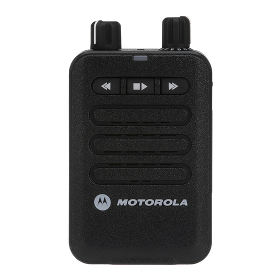
Next/ Fastforward Button Speaker Figure 1-1. MINITOR VI • ON/ OFF/ VOLUME Control Knob – Rotate clockwise until click is heard to turn on pager; rotate counter-clockwise until click is heard to turn off pager. Rotate clockwise to increase volume level;... -
Page 15: Summary Of Bands Available
Model Charts 1.4.1 VHF Tanapa Chart Model Number Tanapa Description A03JAC8JA2AN RLD1047_ 143–174 MHZ SGL CH NON-IS MINITOR VI PAGER A03JAC8JA1AN RLD1048_ 143–174 MHZ SGL CH IS MINITOR VI PAGER A03JAC9JA2AN RLD1049_ 143–174 MHZ FIVE CH NON-IS MINITOR VI PAGER A03JAC9JA1AN RLD1050_ 143–174 MHZ FIVE CH IS MINITOR VI PAGER... -
Page 16: Uhf Tanapa Chart
Introduction: Model Charts 1.4.2 UHF Tanapa Chart Model Number Tanapa Description A04QAC8JA2AN RLE1125_ 406–430 MHZ SGL CH NON-IS MINITOR VI PAGER A04QAC8JA1AN RLE1124_ 406–430 MHZ SGL CH IS MINITOR VI PAGER A04QAC9JA2AN RLE1123_ 406–430 MHZ FIVE CH NON-IS MINITOR VI PAGER A04QAC9JA1AN RLE1122_ 406–430 MHZ FIVE CH IS MINITOR VI PAGER... -
Page 17: Specifications
Co-channel rejection > - 8 dB First Oscillator Stability + / - 10 ppm High level blocking >84 dB ETSI >90 dB Motorola Procedure Audio SPL @ 12” Alert Tone 96 dB Anechoic chamber Voice average 94 dB Anechoic chamber Audio Distortion: Real Time Audio Electrical <... - Page 18 Introduction: Specifications Acoustic < 5% Anechoic chamber Audio Distortion: Stored-Voice Playback Electrical < 6% TIA603-D Acoustic < 7% Anechoic chamber Battery Life Rechargeable >80 hours Alkaline >24 hours Battery Type Li - Ion and Alkaline Package Weight (With Batterys) 6.2 oz. (176 g) Dimensions 4.15”...
-
Page 19: Uhf
Intermodulation >65 dB TIA603-D Spurious Emissions (all bands) Conducted >55 dB TIA603-D Radiated >55 dB TIA603-D Co-channel rejection > - 8 dB First Oscillator Stability + / - 5 ppm High level blocking >84 dB ETSI >90 dB Motorola Procedure... - Page 20 Introduction: Specifications Audio SPL @ 12” Alert Tone 96 dB Anechoic chamber Voice average 94 dB Anechoic chamber Audio Distortion: Real Time Audio Electrical < 4% TIA603-D Acoustic < 5% Anechoic chamber Audio Distortion: Stored-Voice Playback Electrical < 6% TIA603-D Acoustic <...
-
Page 21: Chapter 2 Test Equipment And Service Aids
Chapter 2 Test Equipment and Service Aids Recommended Test Equipment The list of equipment contained in Table 2-1 includes most of the standard test equipment required for servicing MINITOR VI. Use equivalent whenever possible. Table 2-1. Recommended Test Equipment Equipment... -
Page 22: Service Aids
Table 2-2 lists the service aids recommended for working on the pager. While all of these items are available from Motorola, most are standard workshop equipment items, and any equivalent item capable of the same performance may be substituted for the item listed. -
Page 23: Chapter 3 Receive Performance Check
Chapter 3 Receive Performance Check General The pagers meet published specifications through their manufacturing process by utilizing high- accuracy laboratory-quality test equipment. The recommended field service equipment approaches the accuracy of the manufacturing equipment with few exceptions. This accuracy must be maintained in compliance with the manufacturer’s recommended calibration schedule. -
Page 24: Tone Sensitivity
Receive Performance Check: Tone Sensitivity Tone Sensitivity 1. Connect the TEM cell and HP8920 or equivalent equipment as shown in Figure 3-1. below. 2. Put the pager into a TEM Cell, set up the the function switch to test frequency. 3. -
Page 25: Hp8920 Encoder
Receive Performance Check: Tone Sensitivity 3.2.1 HP8920 Encoder Set HP8920 Encoder as below: • SIGNALING ENCODER (AF GENERATOR 2) • Symbol Sequence:12 • Symbol • Definition Table 3-1. Initial Equipment Control Settings Seq. Num. ON Time (ms) OFF Time (ms) Freq. -
Page 26: Tone Sensitivity Specification
Receive Performance Check: Test Mode 3.2.3 Tone Sensitivity Specification Tone sensitivity is dependent on various test conditions such as path losses, orientation of the unit, type of source antenna, test equipment etc. A user may compare measurements to a known good unit. -
Page 27: Chapter 4 Disassembly/Reassembly Procedures
Motorola Service Center listed in Appendix A. Maintenance The procedures in this section provide instructions for the disassembly of the MINITOR VI pager. This product contains static-sensitive devices. Use anti-static handling procedures to prevent electrostatic discharge and component damage. -
Page 28: Pager Disassembly - Detailed
Disassembly/Reassembly Procedures: Pager Disassembly – Detailed Pager Disassembly – Detailed 4.3.1 Removing Back Cover Once the front housing and back cover are disassembled, the IS Intrinsic Safety Rating is voided. Any warranty or repair work must be done by a IS approved repair facility. The unit must be resealed during re- W A R N I N G assembly in order for the unit to maintain the IS Intrinsic Safety Rating for Hazardous Locations. -
Page 29: Figure 4-2. Unlocking Battery Latch
Disassembly/Reassembly Procedures: Pager Disassembly – Detailed Figure 4-2. Unlocking Battery Latch Remove the battery pack. Figure 4-3. Removing Battery Remove the four protective rubber caps (32,33,34) from the Back Housing. ™ Remove the four screws (31) with a TORX T6 screwdriver. -
Page 30: Figure 4-4. Removing Screws And Protective Rubber Caps From Back Housing
Disassembly/Reassembly Procedures: Pager Disassembly – Detailed Protective rubber caps Figure 4-4. Removing Screws and Protective Rubber Caps from Back Housing Separate Back Housing Assembly from Front Housing Assembly with the Pry Opener (Figure 4-5.). Pry Opener Figure 4-5. Seperate Back Housing Assembly from Front Housing Assembly... -
Page 31: Back Housing Disassembly
Disassembly/Reassembly Procedures: Pager Disassembly – Detailed 4.3.1.3 Back Housing Disassembly Remove the Vibrator (Figure 4-6.). Be careful not to damage the terminals of the Vibrator (40) and ventilation felt when removing the vibrator. C a u t i o n Terminal Vibrator (40) Vibrator... -
Page 32: Main Circuit Board Disassembly
Disassembly/Reassembly Procedures: Pager Disassembly – Detailed Volume Knob Kit Channel Knob Kit Figure 4-7. Removing Knobs Pull the latch on the Main PCB Assembly (35) to release the Flex from the connector. Remove the Switch PCB Assembly from the Main PCB Assembly (Figure 4-8.). Switch PCB Assembly Flex Latch... -
Page 33: Io Connector Assembly Disassembly
Disassembly/Reassembly Procedures: Pager Disassembly – Detailed Screw Main PCB Assembly Latch Flex Figure 4-9. Removing Main PCB 4.3.2.3 IO Connector Assembly Disassembly Remove the Bracket IO (29) with Bumper IO (30) from the IO Connector Assembly (25,26,27,28) (Figure 4-10.). Remove the IO Connector Assembly from the Front Housing Assembly. Bumper IO Bracket IO IO Connector Assembly... -
Page 34: Reset Button Disassembly
Disassembly/Reassembly Procedures: Pager Disassembly – Detailed Remove the Front Keypadpad (41) (Figure 4-11.). Screw Speaker Bracket Front Keypad Speaker Bumper Front Housing Assembly Figure 4-11. Removing Speaker and Front Key 4.3.2.5 Reset Button Disassembly Remove the Bracket Reset button (7). Remove the Insulation Sheet (6) and Reset button (5) (Figure 4-12.). -
Page 35: Pager Reassembly - Detailed
Disassembly/Reassembly Procedures: Pager Reassembly – Detailed Pager Reassembly – Detailed 4.4.1 Front Housing Reassembly 4.4.1.1 Reset Button Reasassembly Follow the reverse of Section 4.3.2.5 "Reset Button Disassembly" on page 4-8. 4.4.1.2 Speaker and Front Key Reasassembly Align the guide rib of the Speaker (15) to the guide slot of the Front Housing Assembly. Install the Speaker Bracket (17) and Speaker Bumper (16). -
Page 36: Switch Pcb Assembly Reasassembly
4-10 Disassembly/Reassembly Procedures: Pager Reassembly – Detailed Screw Main PCB Assembly Latch Connector Flex Figure 4-14. Main PCB Assembly 4.4.1.5 Switch PCB Assembly Reasassembly Insert the Flex into the respective connector on the Main PCB Assembly (35). Push both latches into the connector. Switch PCB Assembly Flex Latch... -
Page 37: Pager Reassembly
Disassembly/Reassembly Procedures: Pager Reassembly – Detailed 4-11 Thread of Switches Figure 4-16. Thread of Switches Volume Knob Kit Channel Knob Kit Figure 4-17. Assembling Knobs 4.4.2 Pager Reassembly 4.4.2.1 Back Housing Reasassembly Follow the reverse of Section 4.3.1.3 "Back Housing Disassembly" on page 4-5. 4.4.2.2 Front Housing and Back Housing Reasassembly Apply grease at the corners of the sealing area (Figure 4-18.). -
Page 38: Figure 4-18. Applying Grease
4-12 Disassembly/Reassembly Procedures: Pager Reassembly – Detailed Grease Grease Figure 4-18. Applying Grease Assemble the Back Housing Assembly (11, 12, 13, 14) to the Front Housing Assembly. Use screw kit RLN6520_. Do not reuse original screws or screw caps. The thread lock on the screws is degraded after removing and the caps may have been damaged when removed. -
Page 39: Figure 4-19. Assembling The Back Housing Kit To The Front Housing Kit
Disassembly/Reassembly Procedures: Pager Reassembly – Detailed 4-13 Rubber Cap_R Rubber Cap_L Rubber Cap-Small Screws Terminal Sealing Rubber Figure 4-19. Assembling the Back Housing Kit to the Front Housing Kit NOTE: Ensure the Left and Right Rubber Caps are not reversed. -
Page 40: Pager Exploded Mechanical View And Parts Lists
4-14 Disassembly/Reassembly Procedures: Pager Exploded Mechanical View and Parts Lists Pager Exploded Mechanical View and Parts Lists 4.5.1 MINITOR VI Exploded View and Parts List Figure 4-20. MINITOR VI Exploded View... -
Page 41: Table 4-1. Minitor Vi Exploded View Parts List
Disassembly/Reassembly Procedures: Pager Exploded Mechanical View and Parts Lists 4-15 Table 4-1. MINITOR VI Exploded View Parts List Part Number Description Part Description Item No. Quantity RHN1006_ COVER KIT, FRONT Front Housing HOUSING Light Pipe Message Light Pipe Receive Light Pipe Batt... - Page 42 4-16 Disassembly/Reassembly Procedures: Pager Exploded Mechanical View and Parts Lists Table 4-1. MINITOR VI Exploded View Parts List (Continued) Part Number Description Part Description Item No. Quantity RLN6519_ CONNECTOR Flexible PCB STANDARD-AUDIO, MM, Housing IO KIT, CONNECTOR, IO Pin Terminal...
- Page 43 Disassembly/Reassembly Procedures: Pager Exploded Mechanical View and Parts Lists 4-17 Table 4-1. MINITOR VI Exploded View Parts List (Continued) Part Number Description Part Description Item No. Quantity RLN6514_ PCB Ass’y (VHF), IS, Single PCB (VHF), IS, SGL (RLD1048_) Channel RLN6515_ PCB Ass’y (VHF), Non IS,...
- Page 44 4-18 Disassembly/Reassembly Procedures: Pager Exploded Mechanical View and Parts Lists Table 4-1. MINITOR VI Exploded View Parts List (Continued) Part Number Description Part Description Item No. Quantity RLN6523_ VIBRATOR KIT Vibrator RLN6524_ KEYPAD KIT Front Keypad RLN6509_ MINITOR VI BELT CLIP...
-
Page 45: Chapter 5 Accessories
Chapter 5 Accessories Introduction Motorola provides the following approved accessories to improve the productivity of your pager. 5.1.1 Batteries Part No. Description PMNN4438_ Battery IP56 Li-Ion, IS PMNN4451_ Battery Std IP56 Li-Ion, Non-IS RLN6526_ MINITOR VI Alkaline Battery Tray 5.1.2 Chargers Part No. - Page 46 Accessories: Introduction Notes...
-
Page 47: A.1 Level 1 And 2 Maintenance
When ordering crystals or channel elements, specify the Motorola part number, description, crystal frequency, and operating frequency desired. When the Motorola part number of a component is not known, use the product model number or other related major assembly along with a description of the related major assembly and of the component in question. - Page 48 Replacement Parts & Kits‘ Accessories and Aftermarket Division (AAD) Notes...
- Page 50 MOTOROLA, MOTO, MOTOROLA SOLUTIONS and the Stylized M logo are trademarks or registered trademarks of Motorola Trademark Holdings, LLC and are used under license. All other trademarks are the property of their respective owners. © 2014 Motorola Solutions, Inc. All rights reserved.