
Related Manuals for Sanyo DSR-M814


Summary of Contents for Sanyo DSR-M814
- Page 1 e00_VDH_M814.book Page A Thursday, October 28, 2004 9:59 AM...
-
Page 2: Declaration Of Conformity
PRECAUTION Declaration of Conformity Model Number Trade Name Responsible party : SANYO FISHER COMPANY Address Telephone No. This device complies with Part 15 of the FCC Rules. Operation is subject to the following two conditions: (1) this device may not cause harmful... -
Page 3: Before Use
Hard disk protection The hard disk is checked automatically at power ON. If a hard disk problem is found, the POWER indicator flashes. To initialize the disk or save images stored on the disk, contact a Sanyo service center. - Page 4 30 days after the power plug is disconnected. When disposing of the digital video recorder, contact a Sanyo service center for information on how to dispose of the lithium battery. MENU button The [MENU] button is disabled when the unit is connected to a PC (VA-SW814/VA-SW81LITE).
-
Page 5: Table Of Contents
2. SETTING THE LANGUAGE AND TIME... 33 Changing the language ...33 Setting the time ...34settings ...34 Synchronizing the time with other DSR-M814 DVRs (with two or more DVRs connected) ...36 3. SCREEN SET MENU ... 38 Screen settings...38 MONITOR SET ...39 Naming the cameras ...40... - Page 6 Remote control connections ... 67 Alarm sensor connections... 67 Series recording connections... 67 2. RS-485 SPECIFICATIONS ...68 RS-485 termination switch settings... 68 3. INTERFACE SPECIFICATIONS...69 DVR/VCR command table ... 69 4. SPECIFICATIONS ... 70 Dimensions...71 Cautions when adding a hard disk ...71...
-
Page 7: Introduction
A CD-R/RW drive or CompactFlash card reader can be connected using the USB port. Recorded videos can be copied to external media, and menu data can be transferred to multiple DSR-M814 digital video recorders using external media. * VA-SW81LITE Ver.2 (supplied) or VA-SW814 Ver.2 (sold separately) software is required. -
Page 8: Names And Functions Of Parts
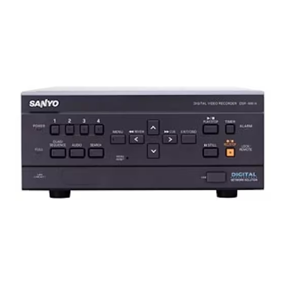
e00_VDH_M814.book Page 7 Thursday, October 28, 2004 9:59 AM 3. NAMES AND FUNCTIONS OF PARTS Front panel POWER QUAD/ SEQUENCE AUDIO FULL (LINK/ACT) 1. POWER indicator ( P.11) Lights when the power is ON. Flashes when there is a problem with the hard disk or fan. -
Page 9: Rear Panel
e00_VDH_M814.book Page 8 Thursday, October 28, 2004 9:59 AM 19. USB port ( P.27, P.63) Used to connect a CompactFlash card reader or CD-R/RW drive. You can copy settings (CompactFlash card only) and recorded videos. 20. [REC/STOP] button and indicator Starts normal recording. -
Page 10: Installation And Connections
e00_VDH_M814.book Page 9 Thursday, October 28, 2004 9:59 AM 4. INSTALLATION AND CONNECTIONS When installing The digital video recorder has ventilation holes. Make sure these holes are not blocked after installation. Do not use the unit in areas with poor ventilation, such as a bookshelf or box. -
Page 11: Connecting To A Network
SWITCHING SWITCHING SWITCHING INSTALLATION AND CONNECTIONS Up to 4000 digital video recorders (DVR) can be connected to a network, and the remote operation software, VA-SW81LITE Ver.2 (supplied) or VA-SW814 Ver.2 (sold separately) allows you to control all connected DVRs, and monitor live video and recorded audio and video from a PC. -
Page 12: Connecting The Power
05 - 10 - 04 08 : 30 : 35 AL 000 15 If a problem occurs when connecting the power or during operation, the POWER indicator flashes as follows to indicate the type of problem. Contact a Sanyo Authorized Service Center if this happens. POWER indicator A problem has been found on the hard disk. -
Page 13: Operation
e00_VDH_M814.book Page 12 Thursday, October 28, 2004 9:59 AM OPERATION 1. ADJUSTING THE DISPLAY At power ON, the operation display area appears at the top of the monitor screen.The operation display area shows the date/time, image quality, remaining time, and other information needed for operations. -
Page 14: Changing The Position Of The Operation Display
e00_VDH_M814.book Page 13 Thursday, October 28, 2004 9:59 AM ADJUSTING THE DISPLAY Displayed symbols The meanings of the symbols shown in the operation display area during recording or playback are listed below. (1) Operation symbol display Recording Playback Still Rewind playback Fast-forward playback Slow playback Reverse slow playback... -
Page 15: Displaying The Image From A Specified Channel In A Single Screen
e00_VDH_M814.book Page 14 Thursday, October 28, 2004 9:59 AM Press the [QUAD/SEQUENCE] button. The image from each channel is displayed sequentially in single screens. Under the default settings, the channel switches automatically every 1 second. To return to the quad screen Press the [QUAD/SEQUENCE] button. -
Page 16: Recording
To change the image quality. ( P.43) When the OVER WRITE recording setting is “ON”, the DVR starts recording from the beginning again. When it is “OFF” and the remaining space reaches zero, recording stops and the FULL indicator lights. ( P.44) You can record and play back images at the same time. -
Page 17: Recording With The Timer (Timer Recording)
e00_VDH_M814.book Page 16 Thursday, October 28, 2004 9:59 AM Recording with the timer (timer recording) Follow the steps below to record the monitored image onto the hard disk at the set time. Press the [TIMER] button. The TIMER indicator lights, and 0 5 - 1 0 - 0 4 0 8 : 3 0 : 3 5 the digital video recorder enters... -
Page 18: Recording Upon Alarm Detection
e00_VDH_M814.book Page 17 Thursday, October 28, 2004 9:59 AM RECORDING Recording upon alarm detection FULL indicator The digital video recorder can make an alarm recording when the motion sensor on the screen or an alarm sensor connected to an ALARM IN terminal detects an alarm condition. -
Page 19: Ending Alarm Recording
e00_VDH_M814.book Page 18 Thursday, October 28, 2004 9:59 AM Ending alarm recording When the alarm duration time (default setting: 20 seconds) ends, “AL” disappears from the operation display, the ALARM indicator stops flashing, and recording stops. When the hard disk’s remaining space for recording reaches zero, the FULL indicator lights and recording stops. -
Page 20: Playing Back Videos
e00_VDH_M814.book Page 19 Thursday, October 28, 2004 9:59 AM 3. PLAYING BACK VIDEOS Follow the steps below to play back videos recorded on the hard disk. Playback [PLAY/STOP] button Press the [PLAY/STOP] button. The [PLAY/STOP] button lights, and the operation display area. The videos recorded on the hard disk are played back in the quad screen. -
Page 21: Viewing Still Images
e00_VDH_M814.book Page 20 Thursday, October 28, 2004 9:59 AM To change the fast-rewind speed Press the [ ] button while rewinding. Press the button once to increase the speed to 7.5 times the playback speed, twice to increase the speed to 15 times the playback speed, 3 times to increase the speed to 30 times the playback speed, and 4 times to increase the speed to 180 times the playback speed. -
Page 22: Switching Audio Channels
e00_VDH_M814.book Page 21 Thursday, October 28, 2004 9:59 AM PLAYING BACK VIDEOS Reverse slow direction [STILL] button Hold down at least 2 seconds With still image display [STILL] button Switching audio channels Follow the steps below to turn the audio ON or OFF, or switch the audio channels. -
Page 23: Searching For Recorded Videos
e00_VDH_M814.book Page 22 Thursday, October 28, 2004 9:59 AM 4. SEARCHING FOR RECORDED VIDEOS Videos recorded on the hard disk can be searched for and played back. There are two search methods available. Video to search Search inscreen You can use the button operations to pause, fast-forward or perform other operations on retrieved images being played back. -
Page 24
e00_VDH_M814.book Page 23 Thursday, October 28, 2004 9:59 AM SEARCHING FOR RECORDED VIDEOS Select “ALARM SEARCH”, and press the [ ] button. The
screen is displayed. (1) NO: Displays the alarm number. (2) CH: Displays the channels of the images that contain alarms. -
Page 25: Date And Time Search
e00_VDH_M814.book Page 24 Thursday, October 28, 2004 9:59 AM Enter the alarm number of the desired video. “AVAILABLE NO” indicates the numbers that can be searched. Enter the approximate number of the desired image. Press the [ ] and [ ] buttons to change the number. - Page 26 e00_VDH_M814.book Page 25 Thursday, October 28, 2004 9:59 AM SEARCHING FOR RECORDED VIDEOS Press the [ ] button, and set the date and time to search. Example: To search for the video from October 26 2004 20:00 (1) (2) (3) (4) (5) (1) Press the [ ] or [ ] button to select “10”...
-
Page 27: Preventing Accidental Operation (Key Lock Function)
e00_VDH_M814.book Page 26 Thursday, October 28, 2004 9:59 AM 5. PREVENTING ACCIDENTAL OPERATION (KEY LOCK FUNCTION) Follow the steps below to set the key lock function, preventing accidental pressing of the operation buttons. Setting the key lock function With the digital video recorder recording or stopped, hold down the [ ] button for about 3 seconds. -
Page 28: Copying Recorded Videos To External Media
e00_VDH_M814.book Page 27 Thursday, October 28, 2004 9:59 AM 6. COPYING RECORDED VIDEOS TO EXTERNAL MEDIA [MENU] button ] button Use the following procedure to copy recorded videos to a CompactFlash card or CD-R/RW. CompactFlash cards and CD-RWs can also be formatted as described below. Do not turn off the power while a video is being copied. - Page 29 (2) A file is created inside that folder with its name reflecting the date and time. If “DVR NAME” has not been set, the name “DSR-M814” will be used when creating folders. The character “+” will be used to replace any slash (/), semi-colon (;), asterisk (*), period (.), or colon (:) characters appearing in “DVR NAME”.
-
Page 30: Formatting A Compactflash Card Or Cd-Rw
e00_VDH_M814.book Page 29 Thursday, October 28, 2004 9:59 AM COPYING RECORDED VIDEOS TO EXTERNAL MEDIA Formatting a CompactFlash card or CD-RW Press the [SEARCH] button while the digital video recorder is recording or stopped. Thescreen appears. Press the [ ] and [ ] buttons to select “FORMAT MEDIA”... -
Page 31: Settings
e00_VDH_M814.book Page 30 Thursday, October 28, 2004 9:59 AM SETTINGS 1. MENU CONFIGURATION This section describes the menu configuration, and which menu item to select for each operation. Operating menu screens ] button ] button [MENU] button ] button [EXIT/OSD] button Press the [MENU] button. -
Page 32: Restoring Items To The Default Settings
e00_VDH_M814.book Page 31 Thursday, October 28, 2004 9:59 AM MENU CONFIGURATION Restoring items to the default settings Follow the steps below to restore the settings in the displayed setting screen to the default settings. Only the displayed settings are restored. Display the setting screen you want to restore. - Page 33 e00_VDH_M814.book Page 32 Thursday, October 28, 2004 9:59 AM MENU CONFIGURATION 8. POWER LOSS/USED TIME ( P.62) Lets you check the date and time of power failures and the elapsed amount of hard disk operation time. 9. MENU UPLOAD/DOWNLOAD ( P.63) Lets you save menu setting values onto a CompactFlash card.
-
Page 34: Setting The Language And Time
e00_VDH_M814.book Page 33 Thursday, October 28, 2004 9:59 AM 2. SETTING THE LANGUAGE AND TIMEYou can perform the following functions: Change the language used to display on screen information. Set the date and time displayed on the normal screen. Set the clock to adjust automatically for Daylight Saving time. -
Page 35: Setting The Time
e00_VDH_M814.book Page 34 Thursday, October 28, 2004 9:59 AM Setting the time (Default setting: 01-01-2004 THU 00:00:00) Be sure to set the correct date and time. The digital video recorder stores the times of recordings for use in operations such as playback and search/playback. Example: Setting May 10, 2004, 8:30 Press the [MENU] button. -
Page 36
e00_VDH_M814.book Page 35 Thursday, October 28, 2004 9:59 AM SETTING THE LANGUAGE AND TIME Press the [ ] or [ ] button to select “MODE” under
. Press the [ ] button. “USE” flashes. Press the [ ] or [ ] button to change the setting. -
Page 37: Synchronizing The Time With Other Dsr-M814 Dvrs (With Two Or More Dvrs Connected)
Thesettings are now finished. SETTING THE LANGUAGE AND TIME Synchronizing the time with other DSR-M814 DVRs (with two or more DVRs connected) This section describes how to have the time synchronized automatically when two or more digital video recorders are connected. - Page 38 e00_VDH_M814.book Page 37 Thursday, October 28, 2004 9:59 AM SETTING THE LANGUAGE AND TIME Press the [ ] or [ ] button to select the desired time, then press the [ button. Set the time After you are finished chaging the settings, press the [EXIT/OSD] button.
-
Page 39: Screen Set Menu
e00_VDH_M814.book Page 38 Thursday, October 28, 2004 9:59 AM 3. SCREEN SET MENUScreen settings MONITOR SET “SEQUENCE” is used to set the time interval used for switching screens when displaying the image from each channel sequentially. 05 - 10 - 04 08 : 30 : 35 AL 00015 “DISPLAY”... -
Page 40: Monitor Set
e00_VDH_M814.book Page 39 Thursday, October 28, 2004 9:59 AM SCREEN SET MENU MOTION SENSOR SET If the motion sensor is set on the monitor, alarm recording is enabled when a moving subject is detected. Example of set motion sensor MONITOR SET [MENU] button ] button ] button... -
Page 41: Naming The Cameras
e00_VDH_M814.book Page 40 Thursday, October 28, 2004 9:59 AM Naming the cameras Camera titles can be up to 10 characters long. You can enter the following characters and symbols: 0 to 9, A to Z, - (hyphen), : (colon), . (period), / (slash), * (asterisk), _ (underbar), (space) [MENU] button [CHANNEL]... -
Page 42: Setting The Motion Sensor
e00_VDH_M814.book Page 41 Thursday, October 28, 2004 9:59 AM SCREEN SET MENU When you have finished making the settings, press the [EXIT/OSD] button. The display returns to the normal screen. The screen displays the set camera title. 0 5 - 1 0 - 0 4 0 8 : 3 0 : 35AL 0 0 0 1 5 Set camera title FLOOR 1 Setting the motion sensor... - Page 43 e00_VDH_M814.book Page 42 Thursday, October 28, 2004 9:59 AM Press the [ ] or [ ] button to select a sensor operation position, then press the [ ] or [ ] button to set the selection (you can set up to 20 positions).
-
Page 44: Recorder Menu
e00_VDH_M814.book Page 43 Thursday, October 28, 2004 9:59 AM 4. RECORDER MENURecording settings The screen lets you make the following recording-related settings: Item Description Changes the recording image quality. Turns audio recording ON/OFF. REC MODE Sets whether to stop recording or to record over previously recorded videos, when the hard disk becomes full. - Page 45 e00_VDH_M814.book Page 44 Thursday, October 28, 2004 9:59 AM Settings ( indicates default setting.) Item Setting Displays the possible recording REC/PB TIME time. Highest image quality. SUPER+ Recording time: At least 56 (SU+) hours (120 GB), or at least 112 hours (240 GB) Super high image quality.
- Page 46 “YES”, then press the [ The normal screen is displayed, and the FULL indicator turns off. The DVR is ready to record again. DISK FULL RESET is only available when “OVER WRITE” is set to “OFF”, and the hard disk is full.
-
Page 47: Alarm Recording Settings
e00_VDH_M814.book Page 46 Thursday, October 28, 2004 9:59 AM Alarm recording settings [MENU] button ] button ] button [EXIT/OSD] button Press the [MENU] button. The [MENU] button lights, and thescreen is displayed. Select “3. RECORDER MENU”, and press the [ ] button. -
Page 48: Setting The Audio Level
e00_VDH_M814.book Page 47 Thursday, October 28, 2004 9:59 AM RECORDER MENU Press the [ ] or [ ] button to select the desired item, then press the [ button. The setting flashes. Press the [ ] or [ ] button to change the setting, then press the [ Repeat steps 4 to 5 to set other items as needed. - Page 49 e00_VDH_M814.book Page 48 Thursday, October 28, 2004 9:59 AM (3) STOP: Enter the time at which to stop timer recording. (4) SET: Setting “ON” enables the entered timer recording setting. Setting “OFF” disables the entered timer recording setting. (5) SAT, DLY: Use these lines for timer recording spanning more than 24 hours.
-
Page 50
e00_VDH_M814.book Page 49 Thursday, October 28, 2004 9:59 AM RECORDER MENU To cancel all timer recording settings Press the [MENU] button. The [MENU] button lights, and the
screen is displayed. Select “3. RECORDER MENU”, and press the [ ] button. -
Page 51: Setting Holidays
e00_VDH_M814.book Page 50 Thursday, October 28, 2004 9:59 AM Set the items in the “WEEK” and “START” columns. (1) Press the [ ] or [ ] button to change “SAT” to “MON”, then press the [ ] button. (2) Press the [ ] or [ ] button to change “--”... -
Page 52: Initializing The Hard Disk/Adding A Hard Disk
e00_VDH_M814.book Page 51 Thursday, October 28, 2004 9:59 AM RECORDER MENU Set the month and day for item No. 1. (1) Press the [ ] button to make “--” (the month) flash. (2) Press the [ ] or [ ] button to set “--” to “11”. (3) Press the [ ] button to make “--”... - Page 53 Press the [EXIT/OSD] button. The display returns to the normal screen. To add a hard disk To add a hard disk, contact a Sanyo service center. When adding a hard disk, use an add-on type hard disk unit (sold separately).
-
Page 54: Display Set
e00_VDH_M814.book Page 53 Thursday, October 28, 2004 9:59 AM 5. DISPLAY SETThe screen lets you turn off the display of the date, time or other information in the operation display area of the playback screen. Use this screen to make settings as needed. -
Page 55: Buzzer Set
e00_VDH_M814.book Page 54 Thursday, October 28, 2004 9:59 AM 6. BUZZER SETThe screen lets you set a warning buzzer to sound when events occur such as alarms being generated or the remaining hard disk space reaching zero. Use this screen to make settings as needed. -
Page 56: Security Lock Set
e00_VDH_M814.book Page 55 Thursday, October 28, 2004 9:59 AM 7. SECURITY LOCK SETYou can set passwords that restrict use of the digital video recorder to administrators and designated users, preventing unauthorized operation. When the security lock is set, a buzzer sounds when an unauthorized user presses any of the digital video recorder’s operation buttons. -
Page 57
e00_VDH_M814.book Page 56 Thursday, October 28, 2004 9:59 AM Select “6. SECURITY LOCK SET”, and press the [ ] button. The
screen is displayed. “LEVEL PASSWORD (4-8) USE” at the top of the screen is the screen title. You cannot move the cursor to this item. -
Page 58: Setting The User Password
e00_VDH_M814.book Page 57 Thursday, October 28, 2004 9:59 AM SECURITY LOCK SET Setting the user password Example: Setting “AB123456” Perform steps 1 and 2 on P.55 and 56. Press the [ ] or [ ] button to move the cursor to “USER”. Press the [ ] button. -
Page 59: Preventing Copying To Cd-R/Rws And Compactflash Cards
e00_VDH_M814.book Page 58 Thursday, October 28, 2004 9:59 AM Preventing copying to CD-R/RWs and CompactFlash cards Making the following settings prevents the copying of videos to a CD-R/RW or CompactFlash card for anyone except the administrator. Set the administrator password. Set COPY TO CD-R/CF to “NO USE”. -
Page 60: Rs-485/Network Set
e00_VDH_M814.book Page 59 Thursday, October 28, 2004 9:59 AM 8. RS-485/NETWORK SET This section describes how to make the RS-485 terminal connections/settings needed to connect to an external device, and how to make the network connections needed to connect to a PC. Network connections and settings You can make digital video recorder menu settings and monitor images from a PC via a network (LAN). - Page 61 Ver.2 remote control software is used, the digital video AUTO recorder’s [STILL] button can be pressed to have the IP address set automatically. The “DVR NAME”, “IP ADDRESS” and “SUB NET MANUAL MASK” are set on the digital video recorder. Set “DVR NAME”, “IP ADDRESS”, and “SUB NET MASK”...
-
Page 62: Rs-485 Connections And Settings
e00_VDH_M814.book Page 61 Thursday, October 28, 2004 9:59 AM RS-485/NETWORK SET RS-485 connections and settings Connect the digital video recorder’s RS-485 (A, B) control terminals to the system controller, hard disk digital recorder or similar device. RS-485A RS-485B 1 2 3 4 5 6 7 8 9 10 11 12 13 14 15 16 17 18 19 [MENU] button ] button ] button... -
Page 63: Power Loss/Used Time
e00_VDH_M814.book Page 62 Thursday, October 28, 2004 9:59 AM 9. POWER LOSS/USED TIMEYou can check the date/time of power failures and the amount of used hard disk operation time. Press the [MENU] button. The [MENU] button lights, and the screen is displayed. -
Page 64: Menu Upload/Download
You can save the settings onto a CompactFlash card. Also, you can load settings saved on CompactFlash cards to the DVR. Do not turn the power OFF when saving/loading menu items to/from a CompactFlash card. Confirm that the light on the CompactFlash card reader is lit before using the card reader with the USB port. -
Page 65
e00_VDH_M814.book Page 64 Thursday, October 28, 2004 9:59 AM To save settings to a CompactFlash card Press the [ ] or [ ] button to select “SAVE MENUS TO CF”, then press the ] button. The
screen is displayed. “NO”... - Page 66 e00_VDH_M814.book Page 65 Thursday, October 28, 2004 9:59 AM MENU UPLOAD/DOWNLOAD Press the [ ] or [ ] button to select “YES”, then press the [ CompactFlash card formatting starts. When formatting has finished, the display returns to the
-
Page 67: Appendix
e00_VDH_M814.book Page 66 Thursday, October 28, 2004 9:59 AM APPENDIX 1. CONTROL TERMINAL SPECIFICATIONS 1 2 3 4 5 6 7 8 9 10 11 12 13 14 15 16 17 18 19 Terminal Name Signal To RS-485 terminal signal RS-485A RS-485 To RS-485 terminal signal... -
Page 68: Remote Control Connections
1 2 3 4 5 6 7 8 9 10 11 12 13 14 15 16 17 18 19 Series recording connections Connect the control terminals by cables as shown below. 5 6 7 8 9 10 11 12 13 Corresponding button 1st DVR Terminal No. 8: COMMON 9: SERIES REC IN 10: NON REC OUT/SERIES REC OUT... -
Page 69: Rs-485 Specifications
Parity check None Stop bit Communication protocol A proprietary Sanyo protocol (SSP: Security Serial Protocol) is used. Use of a special controller for operation is recommended. To obtain this controller, contact your local dealer or a Sanyo service center. RS-485 termination switch settings... -
Page 70: Interface Specifications
Page 69 Thursday, October 28, 2004 9:59 AM 3. INTERFACE SPECIFICATIONS DVR/VCR command table The table below shows the commands supported by the digital video recorder. Left digit Right digit Left digit Right digit CAMERA 1 CAMERA 2 CAMERA 3... - Page 71 e00_VDH_M814.book Page 70 Thursday, October 28, 2004 9:59 AM 4. SPECIFICATIONS Hard disk capacity Television system Picture resolution Video Compression Audio Picture quality Recording type Recording speed Screen Playback Normal recording Recording Timer recording Alarm recording Time/date search Search mode Alarm search Menu language Clock settings...
- Page 72 e00_VDH_M814.book Page 71 Thursday, October 28, 2004 9:59 AM SPECIFICATIONS Dimensions (mm) Front Cautions when adding a hard disk The fan is located below the space for the additional hard disk. When adding a hard disk, perform the following procedures to ensure that the harnesses are not entangled in the fan.
- Page 73 sp00_VDH_M814.book Page 73 Thursday, October 28, 2004 10:04 AM...