Table of Contents
INSTRUCTION MANUAL
Digital Video Recorder
with Multiplexer Function
About this manual
Before installing and using this unit, please read this manual carefully.
Be sure to keep it handy for later reference.
● Refer to the included CD-ROM for the German, French, Spanish and Italian "INSTRUCTION MANUAL".
● Die "BEDIENUNGSANLEITUNG" in den Sprachen Deutsch, Französisch, Spanisch und Italienisch
finden Sie auf der beiliegenden CD-ROM.
● Utilisez le CD-ROM fourni pour consulter le "MANUEL D'INSTRUCTIONS" en allemand, français,
espagnol et italien.
● Consulte en el CD-ROM suministrado el "MANUAL DE INSTRUCCIONES" en alemán, francés, español e
italiano.
● Per il "MANUALE DI ISTRUZIONI" in Tedesco, Francese, Spagnolo e Italiano, fare riferimento al
CD-ROM allegato.
DSR-2004
GB
Table of Contents

Related Manuals for Sanyo DSR-2004


Summary of Contents for Sanyo DSR-2004
- Page 1 ● Utilisez le CD-ROM fourni pour consulter le “MANUEL D’INSTRUCTIONS” en allemand, français, espagnol et italien. ● Consulte en el CD-ROM suministrado el “MANUAL DE INSTRUCCIONES” en alemán, francés, español e italiano. ● Per il “MANUALE DI ISTRUZIONI” in Tedesco, Francese, Spagnolo e Italiano, fare riferimento al CD-ROM allegato. DSR-2004...
-
Page 2: Table Of Contents
SYSTEM settings ....... 29 Setting the DVR ID....... . 29 DESCRIPTION confirmation . -
Page 3: Safety Precautions
This class B digital apparatus complies with Canadian ICES-003. Declaration of Conformity Model Number : DSR-2004 Trade Name : SANYO Responsible party : SANYO FISHER COMPANY Address : 21605 Plummer Street, Chatsworth, California 91311 Telephone No. : (818) 998-7322 • This device complies with Part 15 of the FCC Rules. -
Page 4: These Precautions Must Be Followed For Safety Reasons
Safety precautions These precautions must be followed for safety reasons. b Do not use if the unit emits smoke, strange sounds are heard or odor is emitted. Continued use may cause electrocution and/ or fire. Immediately remove the power plug from the outlet. - Page 5 Safety precautions Warning b Do not use during thunder/thunder storms. Do not use during thunder/thunder storms. Never touch the connection cable during thunder/thunder storms. This may cause electrocution. b Do not place in an unstable position. • Doing so may cause accidents and/or breakdowns through falling or toppling.
- Page 6 Safety precautions b Cleaning the internal components Consult the dealership where this unit was purchased or factory shop for cleaning internal components. Leaving the unit unused for long periods of time may attract dust to the internal components, which in turn may cause fire and/or breakdowns.
- Page 7 Safety precautions Supplied AC Adapter b Use only the supplied AC adapter. Use the supplied AC adapter. Using a different AC adapter can cause fire or electrocution, due to differences in current carrying capacity of the power cord. b Do not connect to other appliances. The AC adapter supplied is to be used with this unit only.
- Page 8 Safety precautions Supplied AC Adapter Caution b Make sure the cable is connected properly. Make sure the AC adapter cable and the connecting cables are connected properly. Tripping over the cable may result in the unit capsizing or falling and cause injury. b Preventing damage to a cable Do not place heavy objects on the AC adapter cable or place the adapter cable near...
-
Page 9: Follow The Points Outlined Below For Proper Use
This may cause exterior damage or wear the paint off. b Copyright information • This manual and software are copyrighted to SANYO Electric Co., Ltd. • Brand and product names used in this manual are the trademarks or registered trademarks of their respective companies. -
Page 10: Main Features
IPS (NTSC) • 4ch audio recording • Remote surveillance and operation via network • VGA video output • Comes with IR remote control unit and DVR utility software Main parts replacement timings Continued use of this unit in a 25°C environment may result in wear and deterioration of the parts of the unit. -
Page 11: Installing A Hard Disk
Installing a hard disk No default hard disk is installed at the time of purchase. To purchase and install a hard disk, consult the dealership where this unit was purchased. Make sure the unit is turned off before installing the hard disk. Unfasten the cover of the unit. -
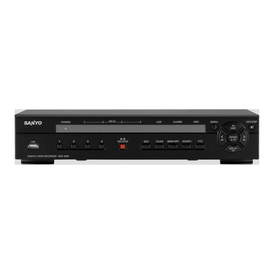
Page 12: Names And Functions Of Parts
Names and functions of parts Front panel There is no power switch on this unit. 1 Power indicator (POWER) The power indicator blinks when the supplied AC adapter is connected. 2 Recording indicator (CH 1/CH 2/CH 3/CH 4) The indicator blinks when a channel is recording. 3 LAN indicator (LAN) The indicator blinks when the unit is connected and used through the LAN cable. -
Page 13: Names Of Each Part And Connections
Names of each part and connections Rear panel Basic connections • Do not turn this unit on before all the connections are complete. Read the instruction manual of each unit carefully. • Make sure each unit is connected properly as faulty connection may result in the unit emitting smoke and/or being damaged. •... -
Page 14: Network Connection (Ethernet)
Names of each part and connections Network connection (ETHERNET) LAN connection b Using the switching hub Use a 10BASE-T/100BASE-TX CAT 5 LAN cable. When controlling the network, connect to hubs such as the switching hub using an Ethernet cable. Monitor Camera (Sold separately) (Sold separately) -
Page 15: Pre-Operation Preparation
Pre-operation preparation Screen display After turning on the power, the message "INITIALIZING" is displayed. Next, the live videos are displayed on a quad-screen. The screen display necessary to operations is displayed on the screen. • The screen display can be hidden except for the recording screen display. (P25) b Quad-screen 1 Operation display : Displayed during live video sequencing. -
Page 16: A Setting The Television System And The Monitor Output
Pre-operation preparation Setting the television system and the monitor output If the television system of the camera to be connected and the type of monitor differ, live videos cannot be monitored on the normal screen. Check the specifications of the equipment to be connected and set the system changeover switch on the rear panel. - Page 17 Pre-operation preparation Press the control button (~) twice and select the SYSTEM, press the ENTER button. The SYSTEM settings screen is displayed. SYSTEM DVR ID DESCRIPTION LOAD DEFAULT ADMIN PASSWORD NETWORK PASSWORD DATE FORMAT CLOCK SET PTZ CONTROL LANGUAGE REMOTE CONTROLLER ID D.S.T./SUMMER TIME...
-
Page 18: C Setting The Language (Language)
Select LANGUAGE using the control button ({|) and select the display language using the control button (}~). Once a language has been selected the display language changes. SYSTEM DVR ID DESCRIPTION LOAD DEFAULT ADMIN PASSWORD NETWORK PASSWORD DATE FORMAT YYYY/MM/DD... -
Page 19: Monitoring The Camera Videos
Monitoring the camera videos Single-screen display Example: Displaying camera 2 on single-screen Press "2" on the camera selection button. The video of camera 2 is displayed on single-screen. Quad-screen display Displays the 4 cameras video connected at once. Press the QUAD button. The quad-screen is displayed. -
Page 20: Operating The Ptz Camera
– RS-422/485 TX+ TX- RX+ RX- Settings Press the MENU button (the MAIN MENU is displayed) and select SYSTEM using the control button (}~). MAIN MENU DVR ID DESCRIPTION LOAD DEFAULT ADMIN PASSWORD NETWORK PASSWORD LIVE RECORD SYSTEM DATE FORMAT... -
Page 21: Recording
Recording This unit allows the following recording modes. Select the recording mode, recording resolution, frame rate and video quality from "RECORD" under the MAIN MENU. (P27) The symbol on the right side of each recording mode (Ex: R) is displayed while recording is in progress. b Types of recording modes A Real time recording (R) ... -
Page 22: Bcontinuous Recording
Recording CONTINUOUS recording Recording starts automatically when this unit is turned on. "C" is displayed on the screen. The connected cameras are simultaneously recorded. The recording mode can be changed using RECORDING under RECORD settings. Settings, such as image quality, can also be set. (P27) 2006/07/14 09:04:54 To stop recording, select RECORDING under RECORD settings using the control button ({|) -
Page 23: Dby Ext. Sensor Recording
Recording BY EXT. SENSOR recording An external sensor can be connected to each channel. Connecting an external switch to an external sensor terminal. Camera (Sold separately) Set the following items using the control button ({|}~). • RESOLUTION • FRAME RATE •... -
Page 24: Eby Schedule Recording
Recording BY SCHEDULE recording Adjusting the following settings using the control button ({|}~). • RESOLUTION • FRAME RATE • CHANNEL • QUALITY Select RECORDING using the control button ({|) and select BY SCHEDULE using the control button (}~). The following settings are necessary when performing sensor detection. - Page 25 Recording b Copying a set recording schedule to other channels Copying the channel 1 schedule to channel Example 1 3 (COPY FROM) Set the channel 1 schedule and press the EXIT/ STOP button. The RECORD screen is displayed again. TIMER SET-CH1 COPY FROM COPY TO - - -...
-
Page 26: Playing Back Recorded Videos
Playing back recorded videos The following recorded videos searching methods are available. 2006/07/14 17:25:37 EVENT SEARCH TIMELINE SEARCH T/D SEARCH GO FIRST GO LAST BOOKMARK b BOOKMARK (P20) Search through copied still images or moving videos. b The function of each button during playback. -
Page 27: Aevent Search
Playing back recorded videos EVENT SEARCH Press the SEARCH button. The menu screen is displayed. EVENT SEARCH TIMELINE SEARCH T/D SEARCH Select EVENT SEARCH using the control button ({|) and press the ENTER button. The SEARCH screen is displayed. Select the date you want to search using the control button ({|}~) and press the ENTER button. -
Page 28: Btimeline Search
Playing back recorded videos TIMELINE SEARCH Press the SEARCH button. The search menu screen is displayed. Select TIMELINE SEARCH using the control button ({|) and press the ENTER button. The SEARCH screen is displayed. If recordings are available, the date is displayed in red. •... -
Page 29: Ego Last
Playing back recorded videos GO LAST Press the SEARCH button. The menu screen is displayed. Select GO LAST using the control button ({|) and press the ENTER button. The last recording is played back. Press the EXIT/STOP button once operations are complete. -
Page 30: Copying The Recorded Videos To A Usb Device
Copying the recorded videos to a USB device Your choice of videos can be copied to a USB device. Selecting these videos is called marking. Still images of live videos and still and moving videos of playbacks in progress can be selected. Marking and copying live videos Connect the USB memory to the USB terminal, copying operations become available. -
Page 31: B Marking And Copying Playback Videos
Copying the recorded videos to a USB device Press the MARK/COPY button. The BACKUP USB DEVICE screen is displayed. BACKUP USB DEVICE CD-RW Select USB STICK (Example) to where the selected videos will be copied using the control button (}~) and press the ENTER button. -
Page 32: Configuration And Function Of The Menu Settings
FORAMT b SYSTEM settings (P29) To perform settings carried out by the manager, such as setting initialization and password, date and time, language and PTZ camera settings. SYSTEM DVR ID DESCRIPTION LOAD DEFAULT ADMIN PASSWORD NETWORK PASSWORD DATE FORMAT YYYY/MM/DD... - Page 33 Configuration and function of the Menu settings b Basic operations of the MAIN MENU Press the MENU button. The PASSWORD input screen is displayed. PASSWORD Press the button 1 four times to enter "1111" and press the ENTER button. The MAIN MENU screen is displayed. •...
-
Page 34: Live Settings
LIVE settings Press the MENU button and enter the password. (P24) The MAIN MENU is displayed, select "LIVE" using the control button ({|}~). MAIN MENU LIVE RECORD NETWORK HDD SET LIVE SEQUENCE SEQ-DWELL TIME 2 SECONDS EVENT BEEP OSD CONTRAST CHANNEL DISPLAY SEQ LIST... -
Page 35: D Setting A Channel
LIVE settings Setting a CHANNEL To set the video settings on each channel. Select an item for each setting using the control button ({|) and select a setting value using the control button (}~). ● Setting a CHANNEL and the channel designation Select CHANNEL using the control button ({|) and select a channel from the following channels using the control button (}~), press the ENTER... -
Page 36: Record Settings
RECORD settings Press the MENU button and enter the password. (P24) The MAIN MENU is displayed, select "RECORD" using the control button ({|}~). MAIN MENU LIVE RECORD NETWORK HDD SET RECORD RESOLUTION QUAD CHANNEL FRAME RATE 1 f/s QUALITY NORMAL RECORDING CONTINUOUS MOTION ZONE... -
Page 37: C Setting The Timer Set
RECORD settings ● Setting the MOTION ZONE (P13) Select the zone where the motion sensor is active. It is necessary to set a detection frame when PARTIAL ZONE is selected. FULL ZONE: The motion sensor is active on the whole screen. PARTIAL ZONE: The motion sensor is active in the set detection frame. -
Page 38: System Settings
Input the unit designation (Example: REC-1) by pressing the control buttons ({|}~) repeatedly and press the ENTER button. The changed unit designation is displayed in DVR ID on the SYSTEM screen. Furthermore, the unit designation is entered in the sent mail when using SEND E-MAIL in NETWORK settings (P35). -
Page 39: D Setting An Admin Password
SYSTEM settings Setting an ADMIN PASSWORD To set a password to enter the menu settings screen of this unit. The initial value is "1111". Select ADMIN PASSWORD using the control button ({|) and press the ENTER button. The Current password input screen is displayed. Input the current password (1111) using the camera selection button (1) and press the ENTER button. -
Page 40: E Setting A Network Password
SYSTEM settings b Restoring the password input Press the MENU button, select SYSTEM and press the ENTER button. Select ADMIN PASSWORD using the control button ({|) and press the ENTER button. The Current password input screen is displayed. ADMIN PASSWORD Current: * * * * - - - -... -
Page 41: J Setting A Remote Controller Id
The initial value is set to "0" and the remote control display is displayed on the monitor, remote operations are always available. SYSTEM DVR ID DESCRIPTION LOAD DEFAULT ADMIN PASSWORD NETWORK PASSWORD DATE FORMAT... -
Page 42: Network Settings
NETWORK settings Press the MENU button and input the password. (P24) The MAIN MENU is displayed, select "NETWORK" using the control button ({|}~). MAIN MENU LIVE RECORD NETWORK HDD SET NETWORK PORT 5445 CLIENT ACCESS BANDWIDTH SAVING NETWORK TYPE DHCP DDNS SEND E-MAIL Setting the PORT... -
Page 43: D Setting The Network Type
NETWORK settings Setting the NETWORK TYPE Select NETWORK TYPE to be connected, and set each setting. Consult the network manager for all necessary information. Select NETWORK TYPE using the control button ({|). Select a type using the control button ({|). •... -
Page 44: E Setting The Send E-Mail
Re-pressing the ENTER button returns the screen to the SEND E-MAIL screen. • MAIL ADDRESS To set the mail address. Example: SEND E-MAIL IP NOTIFICATION EVENT ALARM MAIL ADDRESS @sanyo.com MAIL SERVER NAME mailserver12 23456 PASSWORD ******** RETURN MAIL ADDRESS [email protected] MAIL ADDRESS @ s a n y o . - Page 45 NETWORK settings • MAIL SAVER NAME To set the name of the server for the mail. Example: MAIL SERVER NAME m a i l s e r v e r 1 2 - - - - - - - - - - - - - - - - - - - - - - - - - - - - - - - - ID: To set information for the Internet user, such as the connection ID.
-
Page 46: Hdd Set Settings
HDD SET settings Press the MENU button and input the password. (P24) The MAIN MENU is displayed, select "HDD SET" using the control button ({|}~). MAIN MENU LIVE RECORD NETWORK HDD SET HDD SET OVERWRITE FORAMT Setting the OVERWRITE Allows continuing recording and overwriting old videos once the hard disk capacity is full. -
Page 47: Service Settings
SERVICE settings Press the MENU button and input the password. (P24) The MAIN MENU is displayed, select "SERVICE" using the control button ({|}~). MAIN MENU LIVE RECORD NETWORK HDD SET SERVICE USB UPGARDE SAVE SETUP TO A USB LOAD SETUP FROM A USB USB memory Setting the USB UPGRADE Under service mode. -
Page 48: Operations Using The Network
Operations using the Network This unit can be operated from a PC screen by using the supplied network operation software "Sanyo DVR Utility 2004". Prior to performing network operations make the following preparations. Connection and settings • Network connection: Connect this unit and the PC using a LAN or Internet connection. -
Page 49: To Uninstall The Software
Once the installation is complete, the "DVR Utility 2004" shortcut icon is displayed on the desktop. Double-click this icon to start the software. To uninstall the software Specify "SANYO DVR Utility 2004" in the control panel [Add or Remove Programs] and uninstall. -
Page 50: Connecting To This Unit
Connecting to this unit To start this software, double-click the desktop shortcut icon ( this unit following the procedure below, the camera live video is displayed. b Connecting for the first time Click the connect button on the operation panel. The connection dialog [Connect] is displayed. -
Page 51: Main Screen Structure And Function Of Each Part
Main screen structure and function of each part When connected to this unit, the live video of the camera is displayed on the main screen. Video display area Displays live video or playback video.Can be switched using the operation button on the screen. (P43) •... -
Page 52: Function Of The Operation Panel
Main screen structure and function of each part Function of the operation panel : The display of the icon changes according to the selection made. 1 Address information of this unit 2 Connect/Disconnect button : Displays the [Connect] dialog for connection (P41) : Disconnects the connection 3 Screen display switch button (P44) : To sequence (camera switch) display... -
Page 53: Main Screen Basic Operations
Main screen basic operations Switching the display mode of the screen Allows you to select the display mode for live and playback video. b Switching from quad-screen to single-screen Click the channel selection button on the operation panel or select one screen and double-click. The video of the specified camera is displayed in single-screen. -
Page 54: B Recording Live Video
Main screen basic operations Recording live video b Recording method The present software allows two modes of recording live video from a camera. Automatic recording setting is also available.• Always: Recording is performed when the recording button on the operation panel is set to ON. -
Page 55: E Saving Images
Main screen basic operations Saving images Allows the user to save live video or playback video displayed on the screen on the PC, as still images. Selecting the camera video to be saved. When in quad-screen display, select 1 camera video and click (a red frame surrounds the selected camera) or double-click to switch to single-screen display. -
Page 56: Search Mode Operations
Sets the start point of the video range to be backed up. • END POINT: Sets the end point of the video range to be backed up. • BACK UP: Executes the backup. • DVR/PC: Switches the recorded video search destination (this unit/PC). -
Page 57: A Searching And Playing Recorded Video
Select the search destination (DVR/PC) Select whether to search the video recorded on the DVR (this unit) or the video recorded on the PC. The search destination can be switched interchangeably by clicking [DVR/PC] on the time scale panel. -
Page 58: B Backing Up Dvr Recorded Video
Search mode operations Backing up DVR recorded video DVR (this unit) recorded video can be backed up on the hard disk of a PC in AVI format. Search the recorded video by following the procedure below, specify the video range to be backed up and execute a back Refer to steps 1-3 of "Searching and playing recorded... -
Page 59: Setup Menu Settings
To display the "Setup" screen, click the menu button ( conditions of the DVR (this unit) during connection and the network operations on this screen. Clicking menu in the [Setup Menu] window on the left of the screen displays the specified menu screen. -
Page 60: B Camera Designation Settings (Site)
Setup menu settings Camera designation settings (Site) Sets the administrative designation of each camera connected to this unit. The set designation is displayed on, for example, the camera video. Select the channel designation to be set and click. The selected line is highlighted in blue. Re-click the selected channel designation. -
Page 61: D Event Log Search, View, Save (Log View)
Setup menu settings Event log search, view, save (Log View) Event information can be searched and events can be saved to a PC. Specify the folder to be searched using [Path]. Set the start point of the search range in [From]. If the checkbox [First] is checked, it is automatically set to the first date and time in the folder. -
Page 62: F Disk Settings (Disk)
Setup menu settings Disk settings (Disk) Set the capacity and the drive of the PC where the recorded video is saved. 1 Disk Space Select the drive used for saving and input the allowable capacity (MB). 2 Disk Full Select the option once the capacity is exceeded using the radio button. -
Page 63: Part Names Of The Remote Control
Part names of the remote control Batteries for the remote control are not supplied. Use two AAA batteries. REC/STOP SKIP ENTER REPLAY MENU EXIT SEARCH MARK COPY QUAD 1 REC/STOP button Stops and starts recording of live videos displayed on the monitor. -
Page 64: Specifications
DC 12 V Approximately 25 W During operation: 5°C - 40°C, During storage: -10°C - +50°C 0 - 90 % 350 (W) × 65 (H) × 260 (D) mm 3.2 kg / 0 1 2 SANYO Electric Co., Ltd. Printed in Korea...