Bosch Climate 5000 Installation Manual
Split-type room air conditioner
Hide thumbs
Also See for Climate 5000:
- Service manual (64 pages) ,
- Installation, operation and maintenance manual (24 pages) ,
- User manual (16 pages)

Related Manuals for Bosch Climate 5000


Summary of Contents for Bosch Climate 5000
- Page 1 SPLIT-TYPE ROOM AIR CONDITIONER Bosch Climate 5000 Installation manual Thank you very much for purchasing our air conditioner. Before using your air conditioner, please read this manual carefully and keep it for future reference.
-
Page 2: Table Of Contents
Gas Leak Checks............24 8.2.1. After performing gas leak checks ....... 24 Test Run ................25 9.1. Before Test Run ............25 9.2. Test Run Instructions ..........25 9.2.1. Double-check pipe connections ......... 25 Bosch Climate 5000 6 720 866 139 (2016/07) -
Page 3: Safety Precautions
For all electrical work, use the specified cables. Connect cables tightly, and clamp them securely to prevent external forces from damaging the terminal. Improper electrical connections can 6 720 866 139 (2016/07) Bosch Climate 5000... -
Page 4: Accessories
Remote controller Fixing screw for remote controller holder ST2.9 x 10 Included Remote controller holder Dry battery AAA. LR03 Seal (for cooling & heating models Drain joint only) Owner's manual Installation manual Bosch Climate 5000 6 720 866 139 (2016/07) -
Page 5: Installation Summary - Indoor Unit
Installation Summary – Indoor Unit 15cm (5.9in) 12cm (4.75in) 12cm (4.75in) 2.3m (90.55in) Select Installation Location Determine Wall Hole Position (Page 11) (Page 12) Attach Mounting Plate Drill Wall Hole (Page 12) (Page 12) 6 720 866 139 (2016/07) Bosch Climate 5000... - Page 6 Installation Summary – Indoor Unit Connect Piping Connect Wiring Prepare Drain Hose (Page 25) (Page 17) (Page 14) Wrap Piping and Cable (Page 18) Mount Indoor Unit (Page 18) Bosch Climate 5000 6 720 866 139 (2016/07)
-
Page 7: Unit Parts
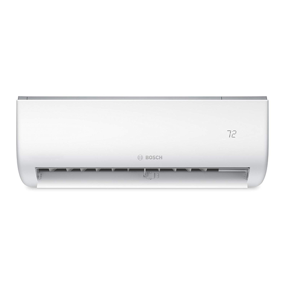
Power Cable (Included) Figure 3-1 NOTE ON ILLUSTRATIONS Illustrations in this manual are for explanatory purposes. The actual shape of your indoor unit may be slightly different. The actual shape shall prevail. 6 720 866 139 (2016/07) Bosch Climate 5000... -
Page 8: Indoor Unit Installation
Place the protective wall cuff (not supplied) in the hole. This protects the edges of the hole and will help seal it when you finish the installation process. Bosch Climate 5000 6 720 866 139 (2016/07) -
Page 9: Mounting Plate Dimensions
Relative distances between screw holes • Model C 5,3 kW Types Correct orientation of Mounting Plate Left rear wall hole Right rear wall hole 65mm 65mm (2.5in) (2.5in) Model D 7 kW Types Figure 4-3 6 720 866 139 (2016/07) Bosch Climate 5000... - Page 10 • DO NOT create a water trap. Refer to Fig. 4.5 for details. DO NOT put the end of drain hose in water or a container that will collect water. Bosch Climate 5000 6 720 866 139 (2016/07)
-
Page 11: Plug The Unused Drain Hole
Kinks in the drain hosewill create water traps. Figure 4-8 NOT CORRECT Do not place the end of the drain hose in water or in containers that collect water. This will prevent proper drainage. Figure 4-9 6 720 866 139 (2016/07) Bosch Climate 5000... -
Page 12: Choose The Right Cable Size
Bundle the drain hose, refrigerant pipes, and communication cable according to Fig. 4.10. Indoor Unit Space behind unit Refrigerant piping Insulation tape Drain hose communication wire Figure 4-10 Bosch Climate 5000 6 720 866 139 (2016/07) -
Page 13: Drain Hose Must Be On Bottom
Again, check that the unit is firmly mounted by applying slight pressure to the left and the right-hand sides of the unit. 30-50m m 30-50m m (1.2-1.95in) (1.2-1.95in) Move to left or right Figure 4-12 6 720 866 139 (2016/07) Bosch Climate 5000... -
Page 14: Outdoor Unit Installation
Near animals or plants that will be harmed by hot air discharge Near any source of combustible gas In a location that is exposed to large amounts of dust In a location exposed to an excessive amounts of salty air Bosch Climate 5000 6 720 866 139 (2016/07) -
Page 15: Special Considerations For Extreme Weather
Rotate the drain joint 90° until it clicks in place facing the front of the unit. Connect a drain hose extension (not included) to the drain joint to redirect water from the unit during heating mode. 6 720 866 139 (2016/07) Bosch Climate 5000... -
Page 16: Unit Mounting Dimensions
Bolt the unit firmly to the brackets. 487 (19.2") 298 (11.73") (30.3"x21.85"x11.81") 800x554x333 514 (20.24") 340 (13.39") (31.5"x21.8"x13.1") 845x702x363 540 (21.26") 350 (13.8") (33.25"x27.63"x14.29") 900x860x315 590 (23.2") 333 (13.1") (35.4"x33.85"x12.4") 945x810x395 640 (25.2") 405 (15.95") (37.2"x31.9"x15.55") Bosch Climate 5000 6 720 866 139 (2016/07) -
Page 17: To Reduce Vibrations Of Wall-Mounted Unit
Insulate unused wires with PVC electrical tape. Arrange them so that they do not touch any electrical or metal parts. Replace the wire cover on the side of the unit, and screw it in place. 6 720 866 139 (2016/07) Bosch Climate 5000... - Page 18 18 Outdoor Unit Installation Cover Outdoor Unit Wiring Diagram is located on the inside of the cable cover on the outdoor unit. Figure 5-6 Bosch Climate 5000 6 720 866 139 (2016/07)
-
Page 19: Refrigerant Piping Connection
Using a pipe cutter, cut the pipe a little longer than the measured distance. Make sure that the pipe is cut at a perfect 90° angle. Refer to Fig. 6.1 for bad cut examples. 6 720 866 139 (2016/07) Bosch Climate 5000... - Page 20 Clamp flare form on the end of the pipe. The end of the pipe must extend beyond the edge of the flare form in accordance with the dimensions shown in the table below. Figure 6-4 Bosch Climate 5000 6 720 866 139 (2016/07)
-
Page 21: Instructions For Connecting Piping To Indoor Unit
Once the pressure is held, leave for 24 hours and check pressure. If the temperature changes allow 0.01MPa per degree change. If correct release nitrogen and start vacuum process. If the pressure is not correct find leak and repair. 6 720 866 139 (2016/07) Bosch Climate 5000... -
Page 22: Air Evacuation
Close the Low Pressure side of the manifold gauge, and turn off the vacuum pump. Wait for 5 minutes, then check that there has been no change in system pressure. Disconnect Vacuum Machine before opening service valves. Bosch Climate 5000 6 720 866 139 (2016/07) - Page 23 Some systems require additional charging depending on pipe lengths. The standard pipe length varies according to local regulations.The standard pipe length is 5m (16'). The additional refrigerant to be charged can be calculated using the following formula. 6 720 866 139 (2016/07) Bosch Climate 5000...
-
Page 24: Electrical And Gas Leak Checks
Note: This may not be required for some locations in the US. WARNING RISK OF ELECTRIC SHOCK All wiring must comply with local and national electrical codes, and must be installed by a licensed electrician. Bosch Climate 5000 6 720 866 139 (2016/07) -
Page 25: Contents Page 9.2.2. If Ambient Temperature Is Below 17°C (63°F)
Manual control button All piping is properly insulated Unit performs COOL function properly Unit performs HEAT function properly Indoor unit louvers rotate properly Indoor unit responds to Figure 9-1 remote controller 6 720 866 139 (2016/07) Bosch Climate 5000... -
Page 26: European Disposal Guidelines
Disposing of this appliance in the forest or other natural surroundings endangers your health and is bad for the environment. Hazardous substances may leak into the ground water and enter the food chain. Bosch Climate 5000 6 720 866 139 (2016/07) - Page 27 Notes Notes 6 720 866 139 (2016/07) Bosch Climate 5000...
- Page 28 Bosch Thermotechnology Ltd Cotswold Way, Warndon, Worcester WR4 9SW. Tel. 0330 123 9559 Bosch Group is a brand name of Bosch Thermotechnology Ltd. worcester-bosch.co.uk...