Table of Contents
Quick Links
1-5
PL201708 EN LIMITED PRODUCT WARRANTY SOLAR INVERTERS - V. 1.0
THREE-PHASE GRID-TIED SOLAR INVERTER
AS-IC01 & AS-IC01-2 (4 kW TO 10 kW)
INSTALLATION INSTRUCTIONS
PD201809 AEG GRID-TIED THREE-PHASE SOLAR INVERTER V.2-18 EN
Solar Solutions GmbH | Schneckenhofstrasse 19 | 60596 Frankfurt am Main | Germany | www.aeg-industrialsolar.de
Table of Contents

Related Manuals for AEG AS-IC01


Summary of Contents for AEG AS-IC01
- Page 1 PL201708 EN LIMITED PRODUCT WARRANTY SOLAR INVERTERS - V. 1.0 THREE-PHASE GRID-TIED SOLAR INVERTER AS-IC01 & AS-IC01-2 (4 kW TO 10 kW) INSTALLATION INSTRUCTIONS PD201809 AEG GRID-TIED THREE-PHASE SOLAR INVERTER V.2-18 EN Solar Solutions GmbH | Schneckenhofstrasse 19 | 60596 Frankfurt am Main | Germany | www.aeg-industrialsolar.de...
- Page 2 AEG GRID-TIED THREE-PHASE SOLAR INVERTER INSTALLATION MANUAL Product series: AEG grid-tied three-phase solar inverters AS-IC01-xxx and AS-IC01-xxx-2 (4 kW to 10 kW) Thank you for choosing the reliability of AEG grid-tied solar inverters! This installation manual is intended for dealers and installers involved in the planning, installation and commissioning of photovoltaic systems deploying AEG solar inverters.
-
Page 3: Table Of Contents
3.2.2 Installation place............................................ 17 3.2.3 Connection cables ..........................................19 3.2.4 Micro breakers ............................................19 3.3 Mechanical installation ..........................................20 3.3.1 Installation of three-phase inverters ................................20 3.4 Electrical installation............................................ 22 PD201809 AEG GRID-TIED THREE-PHASE SOLAR INVERTER (4-10 kW) V.2-18 EN... - Page 4 6.1 AEG WiFi200 (AEG WiFi Stick) communication module ......................... 45 6.1.1 AEG WiFi Stick product overview ..................................45 6.1.2 Remote Monitoring and Local Monitoring; the AEG InverterControl App and Portal ........46 6.2 Optional communication ........................................48 6.3 Pins on inverter ............................................... 48 7.
-
Page 5: Safety Precautions
This section describes relevant warning symbols recurring in the installation and operation manual of AEG three-phase solar inverters of the series AS-IC01 and AS-IC01-2. Icons highlight relevant information for the physical and property safety of the user. Compliance to the provided instructions is essential to prevent physical injury and product damage. -
Page 6: Delivery And Installation
Take measurements to avoid electrostatic discharge during relevant operations. Technical personnel (Operators) who can carry out installation, wiring, commissioning, maintenance, troubleshooting and replacement of the AEG inverter series must meet the following requirements: • The Operator has to be professionally trained •... -
Page 7: Grid-Tied Operation
/ project is located. Ensure reliable installation and electrical connection before operation. Do not unauthorizedly open the inverter cover during operation. The electrical parts and components inside the inverter are electrostatic. PD201809 AEG GRID-TIED THREE-PHASE SOLAR INVERTER (4-10 kW) V.2-18 EN... -
Page 8: Maintenance And Inspection
Periodic inspections are required. If the packaging is damaged for whatever the cause, replace promptly the packaging material. After long-germ storage, the inverters need to be inspected and tested by qualified personnel before they are put into use. PD201809 AEG GRID-TIED THREE-PHASE SOLAR INVERTER (4-10 kW) V.2-18 EN... -
Page 9: Product End Of Life
2. Product Overview The following section describes product appearance, packaging, accessories, technical parameters and other relevant information concerning the AEG grid-tied three-phase solar inverters of the AS-IC01 and AS-IC01-2 series. 2.1 Solar Grid-tied Power Generation Systems 2.1.1 Application Photovoltaic (solar) grid-tied power generation systems consist of solar modules, grid-tied inverters, metering devices, and public grid. -
Page 10: Supported Grid Connection Structure
2.1.2 Supported grid connection structure The AEG inverter series AS-IC01-2 supports TN-S, TN-C, TT and IT grid connection. When applied to the TT connection, the N-to-PE voltage should be less than 30V. -
Page 11: Product Appearance
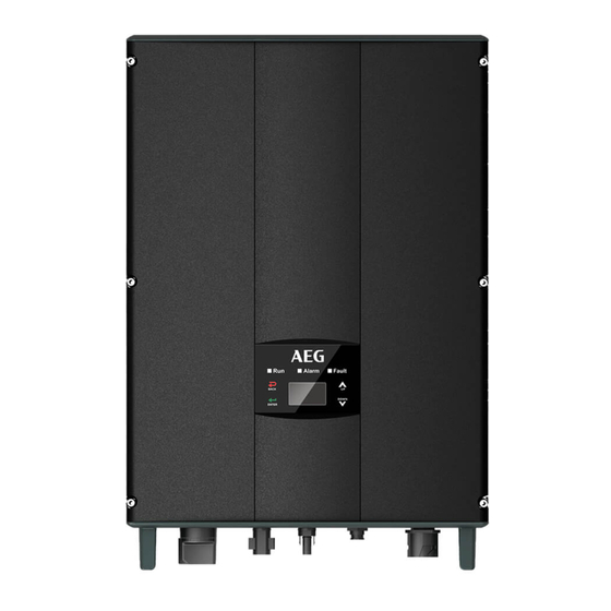
2.2 Product Appearance Figure 3: Scheme of AEG inverter AS-IC01 and AS-IC01-2 series 4 kW to 10 kW Item Instruction Cover Operational panel LED indicators, LCD screen and keypad DC switch For turning on and off the DC input DC input port... -
Page 12: Labels
Trademark Product type / Model (Product Namecode) Serial Number Product characteristics Certification standards Certification standards / Safety Information Manufacturer Information Figure 4: Example of packaging label PD201809 AEG GRID-TIED THREE-PHASE SOLAR INVERTER (4-10 kW) V.2-18 EN... -
Page 13: Product Label
EU WEEE mark. The product cannot be disposed of as household waste. Safety warning: Hazardous electricity can cause shock, burs or death. For proper use the installation manual should be consulted. PD201809 AEG GRID-TIED THREE-PHASE SOLAR INVERTER (4-10 kW) V.2-18 EN... -
Page 14: Product Models
2.3.3 Product models Here below is an overview of the models currently available for the series AS-IC01 and AS-IC01-2. Technical specifications are subject to change without notice. Product type Model Rated output MPPT number power (W) Three-phase (L1, L2, L3, PE) - Page 15 Input overvoltage protection, input overcurrent protection, DC isolation monitoring, DC monitoring, grounding Protection fault current monitoring, grid monitoring, island protection, short circuit protection, overheating protection etc. Table 4: Technical parameters PD201809 AEG GRID-TIED THREE-PHASE SOLAR INVERTER (4-10 kW) V.2-18 EN...
-
Page 16: Dimensions And Weight
2.5 Dimensions and weight Below is an overview of the dimensions and weight of the products in series AS-IC01 and AS-IC01-2. Technical specifications are subject to change without previous notice. Please refer to the related product datasheet which you can also find under www.aeg-industrialsolar.de... -
Page 17: Unpacking Inspection
Should you find any problem, contact the shipping company or your supplier promptly. Following is the detailed packing list of the three-phase inverters: Figure 7: Packing list of three-phase inverter AS-IC01 and AS-IC01-2 (4 kW to 10 kW) Detailed packing list of three-phase inverters of AS-IC01 and AS-IC01-2 series:... -
Page 18: Before Installation
Do not remove any inverter part or component, otherwise damage to the device and physical injury may occur. PD201809 AEG GRID-TIED THREE-PHASE SOLAR INVERTER (4-10 kW) V.2-18 EN... - Page 19 Figure 8A: Optimal mounting height (mm) Figure 8B: Installation spacing (mm) Figure 8C (mm) Correct (and not correct) installation position of the AEG inverter PD201809 AEG GRID-TIED THREE-PHASE SOLAR INVERTER (4-10 kW) V.2-18 EN...
-
Page 20: Connection Cables
AS-IC01-4000 / AS-IC01-4000-2 / AS-IC01-5000 / DC1000V, C16A, 2P AC400V, C16A, 4P AS-IC01-5000-2 / AS-IC01-6000-2 AS-IC01-8000-2 / AS-IC01-10000-2 DC1000V, C25A, 2P AC400V, C25A, 4P Table 10: Breaker specifications PD201809 AEG GRID-TIED THREE-PHASE SOLAR INVERTER (4-10 kW) V.2-18 EN... -
Page 21: Mechanical Installation
Table 11: Size of installation brackets Please follow the below installation steps for three-phase inverters AS-IC01 and AS-IC01-2 (4 to 10 kW): Use the punch positioning plate in the packaging box to determine the punch position as shown in Figure 11A. - Page 22 6. Ensure that the inverter is installed properly and tighten the M5 x 20 bolts into the screw holes on the left and right side of the inverter (tightening torque: 3 N•m) as shown below. PD201809 AEG GRID-TIED THREE-PHASE SOLAR INVERTER (4-10 kW) V.2-18 EN...
-
Page 23: Electrical Installation
Figure 11F: Installation of M5 x 20 bolts 3.4 Electrical installation This section illustrates the detailed electrical installation and related safety instructions for AEG inverter series AS-IC01 and AS-IC01-2. Public Solar modules AEG solar electric grid meter inverter Monitoring Communication... -
Page 24: Connection Of Solar Modules
DC input cable, and ensure that the voltage of each string is within the allowa- ble range of the inverter, as shown in picture 13B below.; PD201809 AEG GRID-TIED THREE-PHASE SOLAR INVERTER (4-10 kW) V.2-18 EN... -
Page 25: Ac Connection Of Three-Phase Inverters 4 Kw To 10 Kw
L1 (A) L2 (B) L3 (C) N neutral wire PE grounding wire Must be connected Table 13 Port instructions of AC connectors for AS-IC01 and AS-IC01-2, 4 kW to 10 kW PD201809 AEG GRID-TIED THREE-PHASE SOLAR INVERTER (4-10 kW) V.2-18 EN... -
Page 26: Operation
Ensure that the mechanical installation meets the requirement mentioned in section 3.3; Ensure that the electrical installation meets the requirement mentioned in section 3.4; 4. Ensure all the switches are on “off” position; PD201809 AEG GRID-TIED THREE-PHASE SOLAR INVERTER (4-10 kW) V.2-18 EN... -
Page 27: Grid-Tied Operation
LCD display, stop the inverter as per section 4.3, and rule out faults according to chapter 7. After all the faults are removed, repeat the operations in chapter 4. PD201809 AEG GRID-TIED THREE-PHASE SOLAR INVERTER (4-10 kW) V.2-18 EN... -
Page 28: Stop
Check the cooling fan noise during fan rotation. Clean the air inlet/outlet if Every six months necessary; If any issue occurred to the fan, replace it immediately. Refer to section 4.4.2. PD201809 AEG GRID-TIED THREE-PHASE SOLAR INVERTER (4-10 kW) V.2-18 EN... -
Page 29: Maintenance Guide
4. Remove the screws and covers of cooling bin or fan box, as shown in Figure 15A and 15B below. Figure 15A: Disassembling the cooling bin Figure 15B: Disassembling the fan box PD201809 AEG GRID-TIED THREE-PHASE SOLAR INVERTER (4-10 kW) V.2-18 EN... - Page 30 8. Disassemble the damaged inverter fan as shown in figure 15C below, then install the new fan back to its original position, and connect the fan power and control cable; Figure 15C: Replace the fan PD201809 AEG GRID-TIED THREE-PHASE SOLAR INVERTER (4-10 kW) V.2-18 EN...
-
Page 31: Display And Operation Panel
LCD display. The LED indicators and the LCD display show the operation states and parameters. The displayed content and parameters can also be set or modified by the operational panel. LED indicators LCD screen Operational panel Figure 16A: Operation Panel PD201809 AEG GRID-TIED THREE-PHASE SOLAR INVERTER (4-10 kW) V.2-18 EN... -
Page 32: Led Indicators
Yellow indicator is on, others are off: Warn (1) Inverter stand-by. Temperature abnormal(E006); Fault (2) Inverter stand-by. DC input fault (E001); Warn Unrecoverable fault Red indicator blinks every 0.5s, others are off: Fault PD201809 AEG GRID-TIED THREE-PHASE SOLAR INVERTER (4-10 kW) V.2-18 EN... -
Page 33: Operation Panel
Curve Graphic Text Parameter Display Area Display Area Status Area Fault Code Menu Figure 16B: Main interface PD201809 AEG GRID-TIED THREE-PHASE SOLAR INVERTER (4-10 kW) V.2-18 EN... -
Page 34: Functions Operation
In total there are 32 history records. Press “ ” and “ ” to review the history record and press “ESC” to exit. The numbers displayed on the top right is the serial number of the record. The numbers displayed in the second line show PD201809 AEG GRID-TIED THREE-PHASE SOLAR INVERTER (4-10 kW) V.2-18 EN... -
Page 35: Statistics
C a s h / p r i c e D a t e / T i m e L a n g u a g e Figure 16G: Statistic information PD201809 AEG GRID-TIED THREE-PHASE SOLAR INVERTER (4-10 kW) V.2-18 EN... - Page 36 Parameters can be set in this interface. LCD menus: PD201809 AEG GRID-TIED THREE-PHASE SOLAR INVERTER (4-10 kW) V.2-18 EN...
- Page 37 V a l / k W h : 0 0 . 5 0 € / 1 k W h next line. After editing the four digits, press “ENT” to save the changes and press “ESC” to exit. The currency types include EUR, USD and CNY. PD201809 AEG GRID-TIED THREE-PHASE SOLAR INVERTER (4-10 kW) V.2-18 EN...
- Page 38 E n d : 2 0 1 2 - 0 2 - 0 1 one of the system setting. The start time needs to be earlier than the end time. The setting date and time are used for statistics. PD201809 AEG GRID-TIED THREE-PHASE SOLAR INVERTER (4-10 kW) V.2-18 EN...
- Page 39 Request the password from your supplier if necessary. MPP Start Volt The MPPT starting voltage can be set in this menu from 120V to 160V under the submenu of ”MPPT start volt”. MPPT Volt 120V PD201809 AEG GRID-TIED THREE-PHASE SOLAR INVERTER (4-10 kW) V.2-18 EN...
- Page 40 “ ” and “ ” to modify, and press “ENT” to confirm. ACOV Volt(phase volt) 263V ACOV Time 0.20s ACUF Freqency 47.6Hz ACUF Time 0.20s ACOF Freqency 51.4Hz ACOF Time 0.20s PD201809 AEG GRID-TIED THREE-PHASE SOLAR INVERTER (4-10 kW) V.2-18 EN...
- Page 41 ACOF1 and ACOF2 together for ACOF protection. ACOV Volt(phase volt) 252V ACOV Time 01.90s ACUF Frequency 49.49Hz ACUF Time 595s ACOF Frequency 50.2Hz ACOF Time 115s Run Restart Time 060s Island protect:on Table 18: Parameter settings PD201809 AEG GRID-TIED THREE-PHASE SOLAR INVERTER (4-10 kW) V.2-18 EN...
-
Page 42: System Information
C o n t r o l M e n u O n / O f f F a c t o r y C l e a r R e s t a r t Figure 16K: Control interface PD201809 AEG GRID-TIED THREE-PHASE SOLAR INVERTER (4-10 kW) V.2-18 EN... - Page 43 P r e s s E S C t o c a n c e l . factory setting. Press “ENT” to confirm the operation or press “ESC” to return. Table 19: Inverter control PD201809 AEG GRID-TIED THREE-PHASE SOLAR INVERTER (4-10 kW) V.2-18 EN...
-
Page 44: Mode Settings
H o l l a n d Figure 16L: Country list Press the “ ” or “ ” button to select the country, and press the ENT button to complete the setting. PD201809 AEG GRID-TIED THREE-PHASE SOLAR INVERTER (4-10 kW) V.2-18 EN... -
Page 45: Monitoring Communication
This section describes the communication connection of inverter and the inverter’s monitoring system (computers, mobile devices etc). The standard communication mode of AEG AS-IC01 and AS-IC01-2 series of grid-tied solar inverters is RS485. The RS485 port can communicate with computers and mobile devices. -
Page 46: Aeg Wifi200 (Aeg Wifi Stick) Communication Module
The WiFi Stick fits the RS485 port of the AEG inverters. WiFi is the standard communication mode for the AEG AS-IC01 and AS-IC01-2. The AEG WiFi Stick features one RS485 and one WiFi communication port for the data transmission. The AEG WiFi Stick features a general serial port which meets the network standards and has built-in TCP/IP protocol stack for the transformation between the user serial port and WiFi port. -
Page 47: Remote Monitoring And Local Monitoring; The Aeg Invertercontrol App And Portal
12. Other frequency: 20MHz, 40MHz and automatic Table 23: AEG WiFi Stick features The AEG WiFi Stick is released from factory in AP mode. It can be connected with the 485 communication interface of inverters and can be operated over computer or mobile software. - Page 48 Remote monitoring is the recommended monitoring setting for the AEG WiFi Stick. You can find exhaustive information on how to set up your WiFi Stick for Remote Monitoring in the document “AEG WiFi 200 Remote Monitoring Quick Setup Guide” to be found here: www.aeg-industrialsolar.de...
-
Page 49: Optional Communication
All operation parameters of the inverter will be transferred through RS485 port, and then to the communication devices. These allow the transfer of the monitoring data to the monitoring system (Web Portal / App). If you need further information on optional communication possibilities, please contact the AEG technical service. 6.3 Pins on inverter... - Page 50 E018 Input OC Input overcurrent DC input overcurrent Inconsistent grid voltage, frequency, E019 Incnst Data consistency fault leakage current or AC/DC injection E020 PowerReversed DC power reversed DC power reversed PD201809 AEG GRID-TIED THREE-PHASE SOLAR INVERTER (4-10 kW) V.2-18 EN...
-
Page 51: Contact
MCU software version: • Fault code: • Fault description: 8. Contact Solar Solutions GmbH Schneckenhofstrasse 19 60596 Frankfurt am Main Germany www.aeg-industrialsolar.de Technical Support: Mail: [email protected] Tel: +31 172 205 011 PD201809 AEG GRID-TIED THREE-PHASE SOLAR INVERTER (4-10 kW) V.2-18 EN... -
Page 52: Annex: Warranty Card
9. Annex: Warranty Card WARRANTY CARD AEG INVERTER SERIES: AS-IC01 / AS-IC01-2 (4 kW-10 kW) Consumer information (please print): Name: Business name: Address: Phone Number: City: State: Zip Code: Email: Installer information: Installer name: Installation Company: Contractor’s license number: Address:... - Page 53 Solar Solutions GmbH Schneckenhofstrasse 19 60596 Frankfurt am Main, Germany www.aeg-industrialsolar.de...