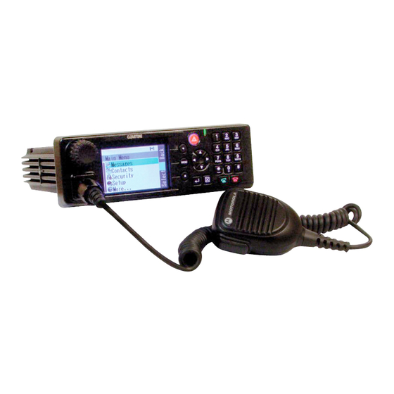
Motorola Cleartone CM5000 Installation Manual
Tetra mobile repeater gateway
380-430 mhz
Hide thumbs
Also See for Cleartone CM5000:
- Feature user manual (124 pages) ,
- Basic service manual (142 pages) ,
- User manual (212 pages)

Related Manuals for Motorola Cleartone CM5000


Summary of Contents for Motorola Cleartone CM5000
- Page 1 TETRA Mobile Repeater Gateway Cleartone CM5000 380-430 MHz (MT912CR) Installation Manual Part Number: 68015000089-A @68015000089@...
-
Page 2: Copyright
Trademarks Motorola, the Motorola Logo and all other trademarks identified as such herein are trademarks of Motorola Inc. All other product or service names are the property of their respective owners. -
Page 3: Important Safety Inforation
Product Safety and RF Exposure booklet enclosed with each radio (Motorola Publication part number 6866537D37) to ensure compliance with Radio Frequency (RF) energy exposure limits. For a list of Motorola-approved antennas and other accessories, visit the following web site which lists approved accessories for your radio model: http://www.motorola.com/governmentandenterprise... - Page 4 CM5000 TETRA Mobile Repeater/Gatewayl Installation Manual Product Safety and RF Exposure THIS PAGE INTENTIONALLY LEFT BLANK...
-
Page 5: Document History
DOCUMENT HISTORY CM5000 TETRA Mobile Repeater/Gateway Installation Manual DOCUMENT HISTORY The following major changes have been implemented in this manual since the previous edition: Edition Description Date 68015000089-A Initial edition January 2009... - Page 6 CM5000 TETRA Mobile Repeater/Gateway Installation Manual THIS PAGE INTENTIONALLY LEFT BLANK...
-
Page 7: Table Of Contents
Further Assistance from Motorola ........ - Page 8 CM5000 TETRA Mobile Repeater/Gateway Installation Manual CONTENTS INSTALLATION ..........21 Introduction .
- Page 9 CONTENTS CM5000 TETRA Mobile Repeater/Gateway Installation Manual APPENDIX ..........51 Product Specific Information.
- Page 10 CM5000 TETRA Mobile Repeater/Gateway Installation Manual THIS PAGE INTENTIONALLY LEFT BLANK...
-
Page 11: Scope
SCOPE CM5000 TETRA Mobile Repeater/Gateway Installation Manual SCOPE Scope of This Manual This manual is intended for use by service technicians familiar with similar types of equipment. It contains information required for the installation of the equipment described and is current as of the printing date. -
Page 12: Cm5000 Manuals And User Guides
CM5000 TETRA Mobile Repeater/Gateway Installation Manual SCOPE CM5000 Manuals and User Guides Installation Instructions 6866539D45 CM5000 Installation Manual (English) Service Manual 6866539D44 CM5000 Basic Service Manual (English) User Guides 6866539D69 CM5000 Basic User Guide (English) 6866539D60 CM5000 Basic User Guide (English, German, French, Spanish, Lithuanian) 6866539D64 CM5000 Basic User Guide (English, Swedish, Polish, Dutch, Norwegian) 6866539D54... -
Page 13: Warranty And Service Support
In instances where the product is covered under a "return for replacement" or "return for repair" warranty, a check of the product should be performed prior to shipping the unit back to Motorola. This is to ensure that the product has been correctly programmed or has not been subjected to damage outside the terms of the warranty. -
Page 14: Service Information
Aftermarket and Accessory Division (AAD). If no part number is assigned, the part is not normally available from Motorola. If a parts list is not included, this generally means that no user-serviceable parts are available for that kit or assembly. -
Page 15: Asia, Pacific Region
Aftermarket and Accessory Division (AAD). If no part number is assigned, the part is not normally available from Motorola. If a parts list is not included, this generally means that no user-serviceable parts are available for that kit or assembly. -
Page 16: Latin America Region
If a 58212-901-4600 complete Motorola part number is assigned to the part, it is available from Motorola. If no part MOTOROLA DO BRASIL LTDA. number is assigned, the part is not normally Av. Chedid Jafet available from Motorola. -
Page 17: Model Information & Accessories
MODEL INFORMATION & ACCESSORIESCM5000 TETRA Mobile Repeater/Gateway Installation Manual MODEL INFORMATION & ACCESSORIES CM5000 Mobile Terminal Model Information Model Specifications* GENERAL RECEIVER TRANSMITTER π ETSi: ETS 300 394-1 Receiver Type: Superheterodyne Modulation Type: /4DQPSK Type Number: Frequency Range: RF Power: 380-430 MHz MT912CR 380-430 MHz... -
Page 18: Accessories Chart
CM5000 TETRA Mobile Repeater/Gateway Installation Manual MODEL INFORMATION & ACCESSORIES Accessories Chart ACCESSORIES Speakers Part Number External speaker 13 watts GMSN4066 Compact external speaker 5 watts GMSN4078 Desktop Solution Part Number Desktop microphone RMN5069 Desktop tray without speaker GLN7318 Desktop power supply GPN6145 DC power cable GKN6266... - Page 19 MODEL INFORMATION & ACCESSORIESCM5000 TETRA Mobile Repeater/Gateway Installation Manual Antennas Part Number 380 - 430 MHz Antenna Combined TETRA and GPS GMAE4248_ 380 - 400MHz Antenna Combined TETRA and GPS GMAE4249_ 410 - 430MHz Antenna Combined TETRA and GPS GMAE4250_ Antenna Mount Panel GMLN4276_ (Choose Whip from below)
- Page 20 CM5000 TETRA Mobile Repeater/Gateway Installation Manual THIS PAGE INTENTIONALLY LEFT BLANK...
-
Page 21: Introduction
Only the specified Motorola parts in this manual should be used. Failure to do so could result in non compliance to the Automotive Directive (72/245/EEC, as amended by 95/54/EC). - Page 22 CM5000 TETRA Mobile Repeater/Gateway Installation Manual INSTALLATION In a vehicle with an airbag, make sure that the mounting location of the mobile terminal, or of any terminal acces- sory, is not in the deployment path of the air bag.
-
Page 23: Dc Power Cable Installation
INSTALLATION CM5000 TETRA Mobile Repeater/Gateway Installation Manual DC Power Cable Installation Installation Planning This terminal must be operated only in negative ground electrical systems. Operating the terminal on a positive ground system will cause the cable fuse to short-circuit. Check the vehicle ground polarity before you begin the installation. -
Page 24: Installation Procedure
CM5000 TETRA Mobile Repeater/Gateway Installation Manual INSTALLATION Installation Procedure Begin the DC power cable installation as follows: Determine a routing plan, keeping in mind where the terminal is to be mounted and make sure that the cable does not rest on sharp edges. Improper handling with the power cable may cause short- ing to ground. - Page 25 INSTALLATION CM5000 TETRA Mobile Repeater/Gateway Installation Manual Fuse (10A) Fuse Holder Adapter Cover Red Lead Red Lead Red Lead (min. 2.5 mm (min. 2.5 mm2) Mounting Hole Ring Lugs Black Lead (min. 2.5 mm To Battery - To Battery + or Chassis Figure 2 Power Cable Assembly Place the fuse holder close to the battery.
-
Page 26: Ignition Sense Cable Installation
CM5000 TETRA Mobile Repeater/Gateway Installation Manual INSTALLATION Ignition Sense Cable Installation Table 2 Ignition Sense Cable Number Description Rating HKN9327 Ignition Sense Cable with fuse 4A Ignition Sense Cable, Length: 3 m 6580283E02 Fuse 4A for Ignition Sense Cable The HKN9327 Ignition Sense Cable allows the terminal to be turned on and off by the vehicle ignition switch. -
Page 27: Terminal Installation
INSTALLATION CM5000 TETRA Mobile Repeater/Gateway Installation Manual Terminal Installation Control Head Installation The Control Head can be removed from the housing and turned to any position within a 180° radius. This provides multiple mounting options for the terminal. For example, the terminal may be mounted on either side of the vehicle to facilitate the safest and most ergonomically ideal position. -
Page 28: Trunnion Installation
CM5000 TETRA Mobile Repeater/Gateway Installation Manual INSTALLATION Trunnion Installation Installation Planning The trunnion allows the terminal to be mounted to a variety of surfaces. The trunnion must be securely fixed to the vehicle chassis. Ensure the surface can support the weight of the terminal. Although the trunnion can be mounted to a plastic dashboard, it is recommended that the mounting screws be located so they penetrate the supporting metal frame of the dashboard. - Page 29 INSTALLATION CM5000 TETRA Mobile Repeater/Gateway Installation Manual TRANSMISSION HUMP MOUNTING Wing Screw Trunnion Mounting Mounting Bracket Surface 28mm (1.12") 46mm 46mm (1.84") (1.84") 73mm 73mm (2.92") (2.92") BELOW DASH MOUNTING Mounting Surface Wing Screw Sheet Metal Screws Figure 6 Transmission Hump Mounting (Top) and Below Dash Mounting (Bottom)
-
Page 30: Desktop Installation
CM5000 TETRA Mobile Repeater/Gateway Installation Manual INSTALLATION Desktop Installation The CM5000 may be desktop mounted. The Desktop Station option provides the terminal with the desk microphone, power supply, desk top tray (without speaker) and external loudspeaker. A separate data device can be connected via the 7-pin Expansion connector on the rear side (located above the 20-pin accessory connector as shown in figure 8). - Page 31 INSTALLATION CM5000 TETRA Mobile Repeater/Gateway Installation Manual Wall- outlet Line Cord with Ground Power Supply Speaker Outdoor Antenna Lightning Protector with Quarter-Wave 12 V Desktop Shorting Stub Power Cable Desk Microphone Antenna Indoor Antenna Cable Antenna Connector BNC Radio in Desktop Tray Figure 7 Desktop Mounting (Part Numbers see following table) Wall-...
- Page 32 CM5000 TETRA Mobile Repeater/Gateway Installation Manual INSTALLATION Table 3 Associated Components Item Description Part Number Desktop Microphone RMN5069 External Speaker 13 W GMSN4066 Small Loudspeaker 5 W GMSN4078 Desktop Tray w/o speaker GLN7318 12V Desktop Power Cable GKN6266 Power Supply Unit PSU GPN6145_ 110V PSU Line Cord US NTN7373_R...
-
Page 33: Dashboard Installation
INSTALLATION CM5000 TETRA Mobile Repeater/Gateway Installation Manual Dashboard Installation Installing the Radio in an Automotive Dashboard Open out the radio cut-out in the dashboard. Secure the Universal DIN Cage supplied into the radio cut-out. Place the Radio into the Cage and secure to bulk head using fixing holes on either side of radio. -
Page 34: Mounting The Radio In The Frame
CM5000 TETRA Mobile Repeater/Gateway Installation Manual INSTALLATION Mounting the Radio in the Frame Provide the electrical connections to the radio, antenna and accessories. Connect the DC power cable directly to the vehicle battery. The fixing tabs should be checked for tightness each time the radio is removed. -
Page 35: Remote Mount Installation
INSTALLATION CM5000 TETRA Mobile Repeater/Gateway Installation Manual Remote Mount Installation Transceiver Remote Back Cover Screws Screws Screws Remote Back Screws Cover PCB Flex Flex Remote Mount Cable Remote Front Cover PCB Control Head Remote Front Cover Figure 10 Remote Mount Installation with Remote Mount Head Table 5: Associated Components Remote Mount Kit Description Part Number... -
Page 36: Assembling The Remote Front Housing To Transceiver Box
CM5000 TETRA Mobile Repeater/Gateway Installation Manual INSTALLATION Assembling the Remote Front Housing to Transceiver Box Connect the flex from the Transceiver unit to the Remote Front Cover PCB. Using screws provided assemble the Remote Front Cover to the Transceiver unit. Installing the Remote Control Head Position the trunnion in the desired location and mark the positions of the mounting holes using the trunnion mounting bracket as a template. -
Page 37: Remote Mount Installation
INSTALLATION CM5000 TETRA Mobile Repeater/Gateway Installation Manual Remote Mount Installation (Remote Mount with Junction Box) Speaker To CM5000 accessory connector External PTT Visor microphone To Ignition GMMN1033_ switch F2 4A Connecting cable External GMKN4192/3/4 alarm Emergency switch Fist Microphone GMMN4063_ or Telephone style handset GMUN1006_ Junction Box GMNL3002_... -
Page 38: Service
CM5000 TETRA Mobile Repeater/Gateway Installation Manual INSTALLATION Service The junction box pcb is not repairable. Please order a new junction box as necessary. Connections Connect all accessories to the junction box. Connect the mobile-terminal-to-Junction box cable to the junction box. Connect the programming cable to the junction box (if required). - Page 39 INSTALLATION CM5000 TETRA Mobile Repeater/Gateway Installation Manual 4 = Connector for programming cable FLN 9636 5 = Connector for accessory connector kit GMBN1021 6 = Connector for adapting a laptop via RS232 cable 7 = TELCO-connector for fist microphone (GMMN4063_) or telephone style handset (GMUN1006_) Figure 14 Connectors on the Junction Box (Rear Panel)
-
Page 40: If3G Dual Mode Interface Adaptor
CM5000 TETRA Mobile Repeater/Gateway Installation Manual INSTALLATION IF3G Dual Mode Interface Adaptor o i t Figure 15 Dual Mode Interface Adaptor. Note: For dual mode operation both RCU50 and IF3G are required. Kit composition: • Interface Box • EX600 interconnection cable (1m) RTS Connection on 8 Pin Din IO Port: •... -
Page 41: Connectors & Pin Assignment Of The Radio
The Expansion Connector provides a 4-wire RS232 interface for connecting Data Devices. The accessory connections shown are not compatible to some other models of Motorola radios. Check the appro- priate accessory or technical manual for further informa- tion. Table 6 20-Pin Accessory Connector... - Page 42 CM5000 TETRA Mobile Repeater/Gateway Installation Manual INSTALLATION Table 6 20-Pin Accessory Connector Function Description RX_AUDIO This is the received RX signal. Output impedance approximate 600 Ohms; unsymmet- rical; output level = 775mV AUDIO_PA_ENABLE This is a digital input. High level or pin open enables the audio PA; Low level disables the audio PA.
-
Page 43: Accessory Connection Plan
GMKN4084 Speaker Extension Cable The accessory connections shown are not compatible to some other models of Motorola radios. Check the appro- priate accessory or technical manual for further informa- tion. Ensure correct position of the accessory connector. DO NOT short pin 16 or pin 1 on the accessory connector to ground;... -
Page 44: Connector & Pin Assignment Of The Control Head
CM5000 TETRA Mobile Repeater/Gateway Installation Manual INSTALLATION Connector & Pin Assignment of the Control Head Flex Pin 1 Cable Front View to Microphone Connector 9 8 7 6 5 4 3 2 1 10 Note: The keypad labeling of the control head may vary according to the specific customer/country concerns. Figure 17 View of the Control Head’s Microphone Connector and Flex Cable Table 7 10-pin Microphone Connector Function... -
Page 45: Connecting Cables
INSTALLATION CM5000 TETRA Mobile Repeater/Gateway Installation Manual Connecting Cables Radio-to-Junction Box Part Number: 3066537B01 Length: 6 m (19.69 feet) MTM700 ACCESSORY CONNECTOR JUNCTION BOX CONNECTOR 20-pin AMP 26-pin DSub from wire wire colour gage (signal name) (signal name) TWISTED PAIR TWIST / 25.4 SPKR + SPKR +... -
Page 46: Vehicle Antenna Installation
CM5000 TETRA Mobile Repeater/Gateway Installation Manual INSTALLATION Vehicle Antenna Installation Mobile Radio Operation and EME Exposure To assure optimal radio performance and that human exposure to radio frequency electromagnetic energy is within the guidelines referenced in this document, transmit only when people inside and outside the vehicle are at least the minimum distance away from a properly installed, externally- mounted antenna.The table below lists the minimum distance for several different ranges of rated radio power. -
Page 47: Selecting An Antenna Site
Motorola offers a glass-mount antenna as an accessory. This antenna should be placed as high as possible on the vehicle. Ensure that a rear-window defogger element does not touch the inductive “button”... -
Page 48: Antenna Installation Procedure
CM5000 TETRA Mobile Repeater/Gateway Installation Manual INSTALLATION Antenna Installation Procedure Mount the antenna according to the instructions provided with the antenna kit. Run the coax- ial cable to the radio mounting location. If necessary, cut off the excess cable and install the cable connector. -
Page 49: External Speaker Installation
INSTALLATION CM5000 TETRA Mobile Repeater/Gateway Installation Manual External Speaker Installation Remove the speaker from the trunnion bracket by loosening the two wing screws. Choose a place to mount the speaker. When mounting the trunnion on the transmission hump, be careful that the transmission housing is not affected. Use the trunnion bracket as a template to mark the positions of the mounting holes. - Page 50 CM5000 TETRA Mobile Repeater/Gateway Installation Manual THIS PAGE INTENTIONALLY LEFT BLANK...
-
Page 51: Appendix
PRODUCT SPECIFIC INFORMATIONCM5000 TETRA Mobile Repeater/Gateway Terminal Installation Manual APPENDIX Product Specific Information for Digital Terminals Type MT912CR This section gives the Service Personnel an overview about product specific notes. This is necessary to take special precautions to avoid the introduction of hazards when operating, installing, servicing or storing equipment. -
Page 52: Fuse Identification
In case of blown fuses during the installation replace ONLY with those of identical value. Never insert ones of different values. Fuse for Power Cable GKN6270/GKN6274: 10A (Motorola Part Number: 65C80283E05) Fuse for Ignition Sense Cable HKN9327: 4A (Motorola Part Number: 65C80283E02) - Page 53 TETRA Mobil-Repeater-Gateway Cleartone CM5000 380–430 MHz (MT912CR) Installationshandbuch Artikelnummer: 68015000089-A @68015000089@...
- Page 54 Form kopiert, reproduziert, geändert, zurückentwickelt oder verteilt werden, ohne dass hierfür eine ausdrückliche schriftliche Genehmigung von Motorola vorliegt. Darüber hinaus werden mit dem Kauf von Produkten von Motorola weder ausdrücklich noch stillschweigend, durch Rechtsverwirkung oder auf andere Weise Lizenzen unter dem Copyright, dem Patent oder den Patentanwendungen von Software von Motorola ausgegeben, außer der Nutzung von normalen, nicht ausschließlich erteilten,...
- Page 55 Betriebsinformationen vertraut gemacht haben, bevor das Funkgerät in Betrieb genommen werden kann. Dieses Heft liegt jedem Funkgerät bei. Auf der folgenden Website finden Sie eine Liste der von Motorola zugelassenen Antennen und anderen Zubehörteilen. Dort ist auch das für Ihr Funkgerätmodell zugelassene Zubehörs aufgeführt: http://www.motorola.com/governmentandenterprise...
- Page 56 CM5000 TETRA Mobil-Repeater/Gateway-Installationshandbuch Produktsicherheit und Funkwellenbelastung DIESE SEITE WURDE ABSICHTLICH LEER GELASSEN...
- Page 57 DOKUMENTVERLAUF CM5000 TETRA Mobil-Repeater/Gateway-Installationshandbuch DOKUMENTVERLAUF In diesem Handbuch wurden seit der vorherigen Ausgabe die folgenden wichtigen Änderungen vorgenommen: Ausgabe Beschreibung Datum 68015000089-A Erstausgabe Januar 2009...
- Page 58 CM5000 TETRA Mobil-Repeater/Gateway-Installationshandbuch DIESE SEITE WURDE ABSICHTLICH LEER GELASSEN...
- Page 59 Weitere Unterstützung durch Motorola ........
- Page 60 CM5000 TETRA Mobil-Repeater/Gateway-Installationshandbuch INHALTSVERZEICHNIS INSTALLATION ..........21 Einleitung .
- Page 61 INHALTSVERZEICHNIS CM5000 TETRA Mobil-Repeater/Gateway-Installationshandbuch ANHANG ........... 51 Produktspezifische Informationen für digitale Mobilfunkgeräte vom Typ MT912CR .
- Page 62 CM5000 TETRA Mobil-Repeater/Gateway-Installationshandbuch DIESE SEITE WURDE ABSICHTLICH LEER GELASSEN...
- Page 63 UMFANG CM5000 TETRA Mobil-Repeater/Gateway-Installationshandbuch UMFANG Umfang dieses Handbuchs Dieses Handbuch ist für die Verwendung durch Servicetechniker bestimmt, die mit vergleichbaren Geräten vertraut sind. Es enthält wichtige Informationen zur Installation der beschriebenen Ausrüstung und entspricht dem Stand des Druckdatums. Änderungen, die nach dem Druckdatum vorgenommen wurden, können durch eine vollständige Überarbeitung des Handbuchs oder als Zusätze eingefügt werden.
- Page 64 CM5000 TETRA Mobile Repeater/Gateway Installation Manual UMFANG CM5000 Handbücher und Bedienungsanleitungen Installationsanweisungen 6866539D45 CM5000 Installation Manual (Englisch) Wartungs- und Installationshandbuch 6866539D44 CM5000 Basic Service Manual (Englisch) Bedienungsanleitungen 6866539D69 CM5000 Basic User Guide (Englisch) 6866539D60 CM5000 Basic User Guide (Englisch, Deutsch, Französisch, Spanisch, Litauisch) 6866539D64 CM5000 Basic User Guide (Englisch, Schwedisch, Polnisch, Niederländisch, Norwegisch)
- Page 65 UMFANG CM5000 TETRA Mobil-Repeater/Gateway-Installationshandbuch Garantie und Service-Support Motorola bietet einen langfristigen Support für seine Produkte. Dieser Support umfasst den vollständigen Austausch und/oder die Reparatur des Produkts während des Garantiezeitraums und Service/Reparatur oder Support für Ersatzteile außerhalb des Garantiezeitraums. Wenden Sie sich vor der Rücksendung von Funkgeräten an die zuständige Motorola-Garantieannahmestelle oder Ihren Motorola-Händler -Lieferanten oder -Wiederverkäufer.
- Page 66 Motorola-Artikelnummer sind bei der Motorola Radio Aftermarket and Accessory Division (AAD) erhältlich. Wenn einem Teil keine Artikelnummer zugewiesen ist, kann dieses in der Regel nicht bei Motorola erworben werden. Wenn ein Teilesatz nicht in der Liste enthalten ist, sind für diesen keine Komponenten erhältlich, die vom Benutzer ausgetauscht werden können.
- Page 67 Motorola-Artikelnummer sind bei der Motorola Radio Aftermarket and Accessory Division (AAD) erhältlich. Wenn einem Teil keine Artikelnummer zugewiesen ist, kann dieses in der Regel nicht bei Motorola erworben werden. Wenn ein Teilesatz nicht in der Liste enthalten ist, sind für diesen keine Komponenten erhältlich, die vom Benutzer ausgetauscht werden können.
- Page 68 MOTOROLA DO BRASIL LTDA. Artikelnummer zugewiesen ist, kann dieses in Av. Chedid Jafet der Regel nicht bei Motorola erworben werden. 222 Bloco D Conjuntos 11,12,21,22 E 41 Ein Asterisk (*) weist darauf hin, dass das Teil Condominio Millennium Office Park...
- Page 69 INFORMATIONEN ZU MODELL UND ZUBEHÖR CM5000 TETRA Mobil-Repeater/Gateway-Installationshandbuch INFORMATIONEN ZU MODELL UND ZUBEHÖR CM5000 Informationen zum Mobilfunkgerätmodell Modellspezifikationen* ALLGEMEIN EMPFÄNGER SENDER π ETSi: ETS 300 394-1 Empfängertyp: Überlagerungsempfänger Modulationstyp: /4DQPSK Typnummer: Frequenzbereich: RF-Leistung: 380 – 430 MHz MT912CR 380 – 430 MHz 5 W/37 dBm 5 W/37 dBm Temperaturbereich für Transceiver:...
- Page 70 CM5000 TETRA Mobil-Repeater/Gateway-Installationshandbuch INFORMATIONEN ZU MODELL UND ZUBEHÖR Zubehörliste ZUBEHÖR Lautsprecher Artikelnummer Externer Lautsprecher, 13 Watt GMSN4066 Kompakter externer Lautsprecher, 5 Watt GMSN4078 Festinstallation Artikelnummer Tischmikrofon RMN5069 Feststationsuntersatz ohne Lautsprecher GLN7318 Tischnetzteil GPN6145 Gleichstrom-Netzkabel GKN6266 Netzstecker (USA) NTN7373 Netzstecker (Europa) NTN7374 Netzstecker (Großbritannien und Nordirland) NTN7375...
- Page 71 INFORMATIONEN ZU MODELL UND ZUBEHÖR CM5000 TETRA Mobil-Repeater/Gateway-Installationshandbuch Antennen Artikelnummer Kombinierte Antenne TETRA und GPS, 380–430 MHz GMAE4248_ Kombinierte Antenne TETRA und GPS, 380–400 MHz GMAE4249_ Kombinierte Antenne TETRA und GPS, 410–430 MHz GMAE4250_ Konsolenmontage-Antenne GMLN4276_ (Wählen Sie unten eine Peitschenantenne aus) Konsolenmontage-Antenne GMLN4277_ (Wählen Sie unten eine Peitschenantenne aus)
- Page 72 CM5000 TETRA Mobil-Repeater/Gateway-Installationshandbuch DIESE SEITE WURDE ABSICHTLICH LEER GELASSEN...
-
Page 73: Installation
Die Installation dieses Produkts in einem Fahrzeug muss den Richtlinien des Fahrzeugherstellers und den Anweisungen in diesem Handbuch entsprechen. Dabei sollten nur die Teile von Motorola, die in diesem Handbuch angegeben sind, verwendet werden. Ansonsten kann dies zur Nichteinhaltung der Kraftfahrzeugrichtlinie (72/245/EWG, geändert... - Page 74 CM5000 TETRA Mobil-Repeater/Gateway-Installationshandbuch INSTALLATION Installieren Sie das Gerät in horizontaler Position in der Nähe des Fahrers, so dass dieser die Bedienelemente sowie das Zubehör gut sehen und bedienen und einfach darauf zugreifen kann. Stellen Sie sicher, dass der Installationsort frei von Schmutz und Feuchtigkeit ist. Vergewissern Sie sich zudem, dass um das Mobilgerät herum genügend Platz für Belüftung und Installation ist.
-
Page 75: Installation Des Gleichstrom-Netzkabels
INSTALLATION CM5000 TETRA Mobil-Repeater/Gateway-Installationshandbuch Installation des Gleichstrom-Netzkabels Planen der Installation Dieses Gerät darf nur in Systemen mit negativem Massepotential betrieben werden. In einem System mit positivem Massepotential verursacht die Sicherung des Netzkabels einen Kurzschluss. Überprüfen Sie daher die Bordspannung des Fahrzeugs, bevor Sie mit der Installation beginnen. -
Page 76: Installationsverfahren
CM5000 TETRA Mobil-Repeater/Gateway-Installationshandbuch INSTALLATION Installationsverfahren Beginnen Sie mit der Installation des Gleichstrom-Netzkabels folgendermaßen: Legen Sie fest, wie Sie das Kabel verlegen wollen und beachten Sie dabei den Installationsort des Geräts. Stellen Sie sicher, dass das Kabel nicht über scharfe Kanten läuft. Ein unsachgemäßer Umgang mit dem Netzkabel kann zu einem Kurzschluss in der Masseleitung führen. - Page 77 INSTALLATION CM5000 TETRA Mobil-Repeater/Gateway-Installationshandbuch Sicherung (10 A) Sicherungshalter Adapter Abdeckung Roter Draht Roter Draht Roter Draht (mind. 2,5 mm (mind. 2,5 mm Montageloch Kabelschuhe Schwarzer Draht (mind. 2,5 mm Zu Batterie (Minuspol) Zu Batterie (Pluspol) oder Karosserie Abbildung 2 Anschluss des Netzkabels Bringen Sie den Sicherungshalter in der Nähe der Batterie an.
-
Page 78: Installation Des Zünderkennungskabels
CM5000 TETRA Mobil-Repeater/Gateway-Installationshandbuch INSTALLATION Installation des Zünderkennungskabels Tabelle 2 Zünderkennungskabel Nummer Beschreibung Bemessungsgröße HKN9327 Zünderkennungskabel mit Sicherung (4 A) Zünderkennungskabel, Länge: 3 m 6580283E02 Sicherung (4 A) für Zünderkennungskabel Mithilfe des Zünderkennungskabels HKN9327 kann das Gerät über die Zündung des Fahrzeugs ein- und ausgeschaltet werden. -
Page 79: Installation Des Funkgeräts
INSTALLATION CM5000 TETRA Mobil-Repeater/Gateway-Installationshandbuch Installation des Funkgeräts Installation des Bedienteils Das Bedienteil kann aus dem Gehäuse entnommen und in jede Position in einem Radius von 180° gebracht werden. Dadurch kann das Gerät auf verschiedene Weise installiert werden. Das Gerät kann beispielsweise an jeder Seite des Fahrzeugs installiert werden, so dass höchste Sicherheit und eine ergonomisch optimale Position gewährleistet sind. -
Page 80: Installation Der Halterung
CM5000 TETRA Mobil-Repeater/Gateway-Installationshandbuch INSTALLATION Installation der Halterung Planen der Installation Mit der Halterung kann das Gerät an verschiedenen Oberflächen angebracht werden. Die Halterung muss an der Karosserie sicher angebracht werden. Vergewissern Sie sich, dass die Oberfläche das Gewicht des Geräts tragen kann. Die Halterung kann zwar an einem Armaturenbrett aus Plastik installiert werden, es wird jedoch empfohlen, die Montageschrauben am Metallrahmen des Armaturenbretts anzubringen. - Page 81 INSTALLATION CM5000 TETRA Mobil-Repeater/Gateway-Installationshandbuch MONTAGE AM MITTELTUNNEL Flügelschraube Lasche Lasche Montagefläche Halterung Lasche 28 mm (1,12") 46 mm 46 mm (1,84") (1,84") 73 mm 73 mm (2,92") (2,92") MONTAGE UNTER DEM ARMATURENBRETT Montagefläche Flügelschraube Metallblechschrauben Abbildung 6 Montage am Mitteltunnel (oben) und unter dem Armaturenbrett (unten)
-
Page 82: Festinstallation
CM5000 TETRA Mobil-Repeater/Gateway-Installationshandbuch INSTALLATION Festinstallation Für das CM5000 ist auch eine Festmontage möglich. Bei der Feststations-Option verfügt das Gerät über ein Tischmikrofon, Stromversorgung, einen Feststationsuntersatz (ohne Lautsprecher) und externe Lautsprecher. Über den 7-Pin-Erweiterungsanschluss auf der Rückseite (über dem 20-Pin-Zubehöranschluss, wie in Abb. 8 gezeigt) kann ein separates Datengerät angeschlossen werden. Wenn eine Außenantenne benutzt wird, ist ein entsprechend geerdeter Blitzableiter mit Lambda/4-Stichleitung zwischen der Außenantenne und dem Antenneneingang des... - Page 83 INSTALLATION CM5000 TETRA Mobil-Repeater/Gateway-Installationshandbuch Wandsteckdose Geerdetes Netzkabel Netzteil Außenantenne Lautsprecher Blitzableiter mit Lambda/ 4-Stichleitung Netzkabel, 12 V Tischmikrofon oder Antennenkabel Innenantenne BNC-Antennenanschluss Funkgerät in Feststationsuntersatz Abbildung 7 Festmontage (Artikelnummern vgl. Tabelle) Wandsteckdose Geerdetes Netzkabel RS232- Schnittstellenkabel Laptop Netzteil Lautsprecher Außenantenne Blitzableiter mit Lambda/ 4-Stichleitung Netzkabel, 12 V...
- Page 84 CM5000 TETRA Mobil-Repeater/Gateway-Installationshandbuch INSTALLATION Tabelle 3 Dazugehörige Komponenten Element Beschreibung Artikelnummer Tischmikrofon RMN5069 Externer Lautsprecher, 13 W GMSN4066 Kleiner Lautsprecher, 5 W GMSN4078 Feststationsuntersatz ohne Lautsprecher GLN7318 Netzkabel, 12 V GKN6266 Netzteil GPN6145_ Netzkabel für USA, 110 V NTN7373_R Netzkabel für Europa, 230 V NTN7374_R Netzkabel für Großbritannien und Nordirland, 240 V NTN7375_R...
-
Page 85: Installation Am Armaturenbrett
INSTALLATION CM5000 TETRA Mobil-Repeater/Gateway-Installationshandbuch Installation am Armaturenbrett Installieren des Funkgeräts am Armaturenbrett eines Fahrzeugs Öffnen Sie die Aussparung für das Radio im Armaturenbrett. Bringen Sie das mitgelieferte Universal DIN-Gehäuse in der Aussparung für das Radio an. Schieben Sie das Funkgerät in das Gehäuse und befestigen Sie es unter Zuhilfenahme der Befestigungslöcher an den Seiten des Geräts an der Stirnwand. -
Page 86: Montage Des Funkgeräts Am Rahmen
CM5000 TETRA Mobil-Repeater/Gateway-Installationshandbuch INSTALLATION Montage des Funkgeräts am Rahmen Schließen Sie das Funkgerät, die Antenne und das Zubehör an die Stromzufuhr an. Verbinden Sie das Gleichstrom-Netzkabel direkt mit der Autobatterie. Überprüfen Sie jedes Mal, wenn Sie das Funkgerät entfernen, ob die Befestigungslaschen noch fest sitzen. Die Laschen können befestigt werden, indem ein großer Schlitzschraubendreher in den Schlitz hinter der Lasche gesteckt wird. -
Page 87: Remote-Montage
INSTALLATION CM5000 TETRA Mobil-Repeater/Gateway-Installationshandbuch Remote-Montage Transceiver Rückseitige Remote-Abdeckung Schrauben Schrauben Schrauben Rückseitige Schrauben Remote-PCB- Abdeckung Flexkabel Flexkabel Remote-Montage- Kabel Vorderseitige Remote- PCB-Abdeckung Bedienteil Vorderseitige Remote-Abdeckung Abbildung 10 Remote-Montage mit dem Remote-Montagemodul Tabelle 5 Komponenten für das Remote-Montage-Kit Beschreibung Artikelnummer Remote-Montage-Kit, CM5000 GMLN4741A Remote-Montage-Kabel (5,5 m), abgeschirmt 3066579B01... -
Page 88: Anbringen Der Vorderseitigen Remote-Abdeckung An Den Transceiver
CM5000 TETRA Mobil-Repeater/Gateway-Installationshandbuch INSTALLATION Anbringen der vorderseitigen Remote-Abdeckung an den Transceiver Schließen Sie das Flexkabel vom Transceiver an die vorderseitige PCB-Abdeckung an. Schließen Sie die vorderseitige Remote-PCB-Abdeckung mithilfe der mitgelieferten Schrauben an den Transceiver an. Installation des Remote-Bedienteils Bringen Sie die Halterung an der gewünschten Stelle an und markieren Sie die Position der Montagelöcher mithilfe der Befestigung für die Halterung. -
Page 89: Remote-Montage
INSTALLATION CM5000 TETRA Mobil-Repeater/Gateway-Installationshandbuch Remote-Montage (Remote-Montage mit Anschlussdose) Lautsprecher Zu CM5000-Zubehöranschluss Extern & PTT Visiermikrofon GMMN1033_ Zu Zündschloss F2 4A Anschlusskabel Externer GMKN4192/3/4 Alarm Notrufschalter Handmikrofon GMMN4063_ oder Telefon-Handset GMUN1006_ Anschlussdose GMNL3002_ Zubehör- Stecker-Kit Programmierkabel RS232 GMBN1021_ FLN9636_ Standardkabel Laptop Laptop Abbildung 12 Remote-Montage mit Anschlussdose Allgemein... -
Page 90: Kundendienst
CM5000 TETRA Mobil-Repeater/Gateway-Installationshandbuch INSTALLATION Kundendienst Die PCB-Anschlussdose kann nicht repariert werden. Bestellen Sie bei Bedarf eine neue Anschlussdose. Verbindungen Zum Anschluss von Zubehör an die Anschlussdose. Verbinden Sie das Kabel für die Verbindung des Funkgeräts mit der Anschlussdose. Verbinden Sie das Programmierkabel mit der Anschlussdose (falls erforderlich). 1 = Anschlusskabel von der Anschlussdose zum CM5000 (Zubehöranschluss an der Rückseite) - Page 91 INSTALLATION CM5000 TETRA Mobil-Repeater/Gateway-Installationshandbuch 4 = Anschluss für Programmierkabel FLN 9636 5 = Anschluss für Zubehöranschlusssatz GMBN1021 6 = Anschluss für Laptop über RS232-Kabel 7 = TELCO-Anschluss für Handmikrofon (GMMN4063) oder Telefon-Handset (GMUN1006_) Abbildung 14 Anschlüsse an der Anschlussdose (Rückseite) Mithilfe des Zünderkennungskabels HKN9327 kann das CM5000 über die Zündung des Fahrzeugs ein- und ausgeschaltet werden.
-
Page 92: If3G Dualmodus-Schnittstellenadapter
CM5000 TETRA Mobil-Repeater/Gateway-Installationshandbuch INSTALLATION IF3G Dualmodus-Schnittstellenadapter Netzkabel GKN6266A S-Verbindung Funkgerät -Schnittstellenbox Funkgerät m e-Montage-Kabel Netzkabel Dualmodus-Schnittstellenadapter Abbildung 15 Hinweis: Für den Betrieb im Dualmodus ist sowohl RCU50 als auch IF3G erforderlich. Umfang des Satzes: • Schnittstellenbox • EX600 Anschlusskabel (1 m) RTS Verbindung an 8-Pin-Din-IO-Anschluss: •... -
Page 93: Anschlüsse Und Pins Des Funkgeräts
In diesem Abschnitt wird die Pinbelegung des Zubehöranschlusses und des Erweiterungsanschlusses beschrieben. Der Erweiterungsanschluss bietet eine vierpolige RS232-Schnittstelle für den Anschluss von Datengeräten. Die abgebildeten Zubehöranschlüsse sind mit einigen anderen Motorola-Funkgeräten nicht kompatibel. Für weitere Informationen konsultieren Sie bitte das entsprechende Zubehörhandbuch oder technische Handbuch. - Page 94 CM5000 TETRA Mobil-Repeater/Gateway-Installationshandbuch INSTALLATION Tabelle 6 20-Pin-Zubehöranschluss Funktion Beschreibung NOTRUF Zur Aktivierung dieser Funktion muss der Pin mit der Masse verbunden sein. Dadurch wird das Funkgerät eingeschaltet. ZÜNDUNG Wenn dieser Pin an die Zündung des Fahrzeugs angeschlossen wird, wird das Funkgerät automatisch eingeschaltet, wenn die Zündung des Fahrzeugs betätigt wird.
-
Page 95: Plan Für Die Zubehöranschlüsse
Buzzer GMKN4084 Lautsprecher-Verlängerungskabel Die abgebildeten Zubehöranschlüsse sind mit einigen anderen Motorola-Funkgeräten nicht kompatibel. Für weitere Informationen konsultieren Sie bitte das entsprechende Zubehörhandbuch oder das technische Handbuch. Stellen Sie die korrekte Position des Zubehöranschlusses sicher. VERMEIDEN SIE UNBEDINGT einen Erdung von Pin 16 oder Pin 1 des Zubehöranschlusses;... -
Page 96: Anschluss- Und Pinbelegung Des Bedienteils
CM5000 TETRA Mobil-Repeater/Gateway-Installationshandbuch INSTALLATION Anschluss- und Pinbelegung des Bedienteils Pin 1 Flexkabel Vorderansicht auf Mikrofonanschluss 9 8 7 6 5 4 3 2 1 10 Hinweis: Die Beschriftung der Tastatur des Bedienteils kann je nach kunden-/länderspezifischen Anforderungen variieren. Abbildung 17 Ansicht des Mikrofonanschlusses und Flexkabels des Bedienteils Tabelle 7 10-Pin-Mikrofonanschluss Funktion Beschreibung... -
Page 97: Anschlusskabel
INSTALLATION CM5000 TETRA Mobil-Repeater/Gateway-Installationshandbuch Anschlusskabel Funkgerät zur Anschlussdose Artikelnummer: 3066537B01 Länge: 6 m ANSCHLUSS DER MTM700 ZUBEHÖRANSCHLUSS ANSCHLUSSDOSE 20 Pin AMP 26 Pin DSub Kabel- Kabelfarbe (Signalbezeichnung) dicke (Signalbezeichnung) VERDRILLTES VERDRILLT / 25,4 LEITUNGSPAAR LAUTSPR + LAUTSPR + BLAU RX_AUDIO RX_AUDIO LAUTSPR - BRAUN... -
Page 98: Installation Der Fahrzeugantenne
CM5000 TETRA Mobil-Repeater/Gateway-Installationshandbuch INSTALLATION Installation der Fahrzeugantenne Betrieb des mobilen Funkgeräts und Belastung durch elektromagnetische Strahlung Um eine optimale Leistung des Funkgeräts zu gewährleisten und die Funkwellenbelastung durch elektromagnetische Strahlung im Rahmen der in diesem Dokument genannten Richtwerte zu halten, übertragen Sie nur dann, wenn die Menschen, die sich im Fahrzeug oder in dessen Nähe befinden, einen Mindestabstand zu der ordnungsgemäß... -
Page 99: Auswahl Eines Antennenstandorts
Empfangsstörungen führen. Zum Zubehör von Motorola gehört auch eine glasmontierte Antenne. Diese Antenne sollte so hoch wie möglich am Fahrzeug angebracht werden. Vergewissern Sie sich, dass die Scheibenheizung der Rückscheibe nicht mit dem „Induktionspunkt“ an der Montagevorrichtung der Antenne in Berührung kommt. -
Page 100: Installation Der Antenne
CM5000 TETRA Mobil-Repeater/Gateway-Installationshandbuch INSTALLATION Installation der Antenne Montieren Sie die Antenne den mit dem Antennensatz entsprechend den mitgelieferten Instruktionen. Verlegen Sie das Koaxialkabel zu der Stelle, wo die Antenne montiert werden soll. Kürzen Sie das Kabel gegebenenfalls und installieren Sie den Kabelanschluss. Verbinden Sie den Antennenkabelanschluss mit dem Antennenanschluss an der Rückseite des Funkgeräts. -
Page 101: Installation Externer Lautsprecher
INSTALLATION CM5000 TETRA Mobil-Repeater/Gateway-Installationshandbuch Installation externer Lautsprecher Entfernen Sie den Lautsprecher von der Halterungsbefestigung, indem Sie die beiden Flügelschrauben lösen. Wählen Sie einen Platz aus, an dem Sie den Lautsprecher montieren möchten. Achten Sie bei der Montage der Halterung am Mitteltunnel darauf, dass das Getriebegehäuse nicht beschädigt wird. - Page 102 CM5000 TETRA Mobil-Repeater/Gateway-Installationshandbuch DIESE SEITE WURDE ABSICHTLICH LEER GELASSEN...
- Page 103 PRODUKTSPEZIFISCHE INFORMATIONEN CM5000 TETRA Mobil-Repeater/Gateway-Funkgerät-Installationshandbuch ANHANG Produktspezifische Informationen für digitale Mobilfunkgeräte vom Typ MT912CR Dieser Abschnitt bietet Service-Mitarbeitern einen Überblick über produktspezifische Hinweise. Diese enthalten wichtige Vorsichtsmaßnahmen, die eingehalten werden müssen, um Gefahrensituationen zu vermeiden, die bei Betrieb, Installation, Wartung und Lagerung des Geräts auftreten können. Dieses Funkgerät erfüllt die jeweils geltenden Sicherheitsstandards, wenn es wie beschrieben eingesetzt wird.
- Page 104 CM5000 TETRA Mobil-Repeater/Gateway-Installationshandbuch PRODUKTSPEZIFISCHE INFORMATIONEN Sicherungsidentifizierung Ersetzen Sie während der Installation durchgebrannte Sicherungen NUR durch Sicherungen derselben Wertigkeit. Setzen Sie niemals Sicherungen mit abweichenden Wertigkeiten ein! Sicherung für Netzkabel GKN6270/GKN6274: 10 A (Motorola-Artikelnummer: 65C80283E05) Sicherung für Zünderkennungskabel HKN9327: 4 A (Motorola-Artikelnummer: 65C80283E02)